Input Devices
Task:
- Measure the analog levels and digital signals in an input device
Daniel's and Christoph's Part:
Reading a Quadrature Signal
The magnetic encoder on Christoph's motor board can give a really high resolution absolute angle position output if you bother to read it via SPI. And while that feature is cool, it is more than needed for a lot of applications, and way too slow.
For realtime applications other interfaces are way better, one of them being quadrature as used here. It's a simple system, mainly consisting of two signal lines (usually called A and B), each of which switches between two states (high and low, in our case). When the measured position changes a certain amount, the lines switch, with their switching off by a quarter of a period.
Since the information you get is incremental (as in, you only get "it moved for 0.2 degrees", not an absolute "we're at 12.7 degrees"), you might lose some of that, and errors could accumulate. Also, you have to get some kind of zero point to initialise your system. To tackle that, the sensor also offers an index signal, emitting a high when it measures precisely the zero position, and a low otherwise.
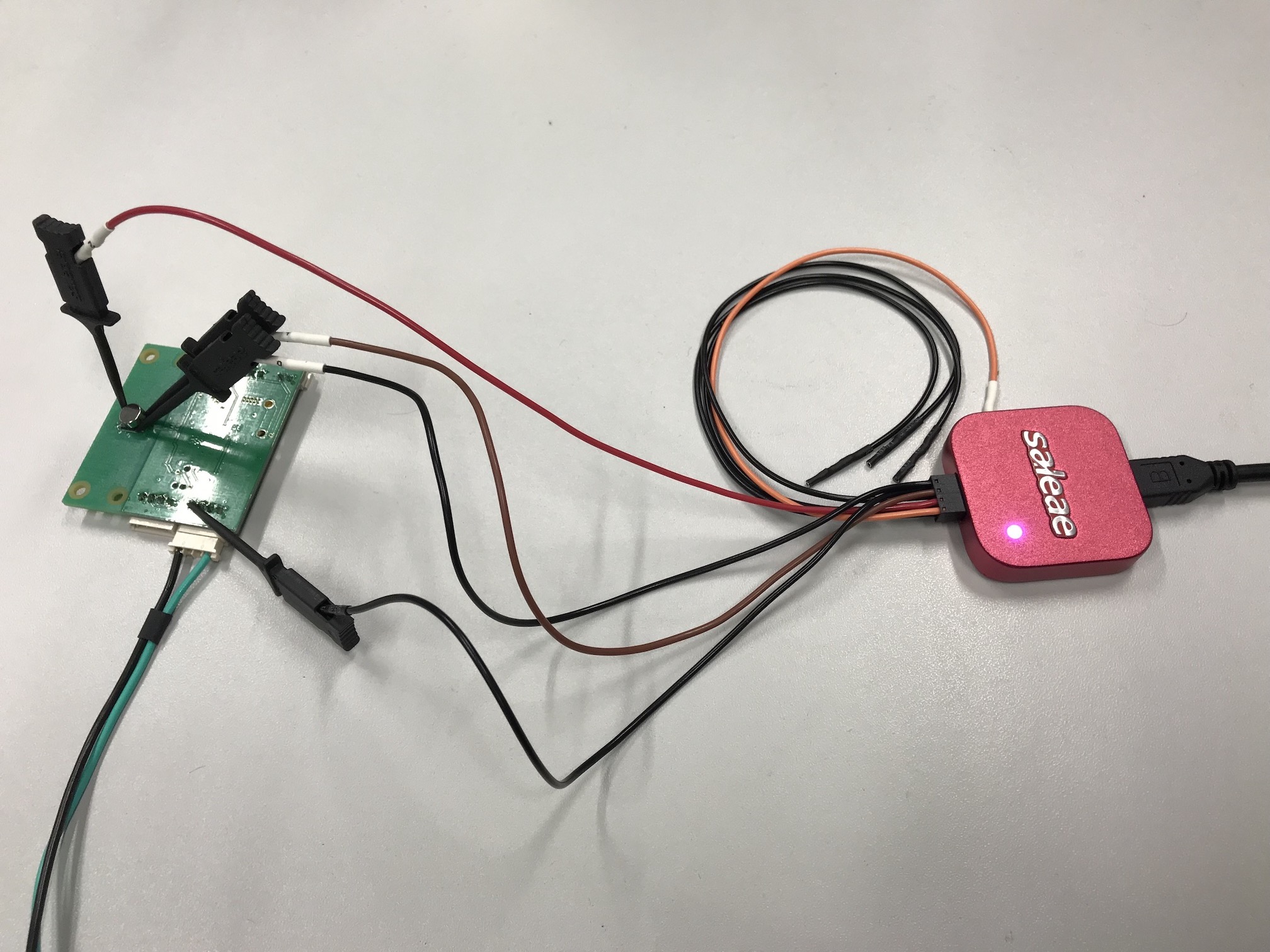
Since there were no analog levels to measure, we decided to measure digital values over time, to get a representation of what the sensor output means. Holding a magnet over the sensor proved to be quite problematic, as the sensor is so sensitive and precise that it's almost impossible to keep the magnet still enough for reading a "no movement". Electrically, the measurement setup is simple, though: Daniel's Logic 8 is connected to ground (the clamp in front, at a pin of the CAN / power jack), Signals A and B (the clamps to the right of the sensor chip) and the Index signal (the clamp to the left).
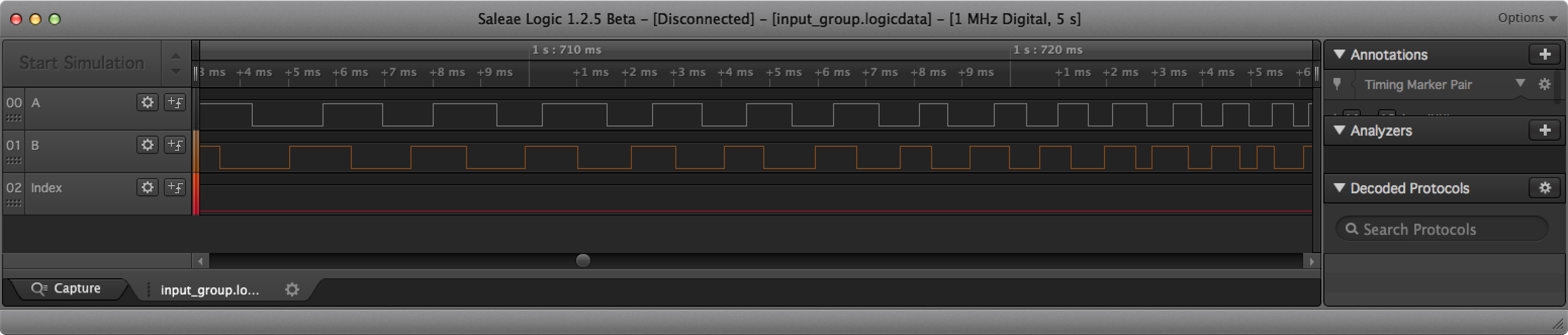
Accelerating, in general, will lead to the time between switching becoming shorter. This first sample shows movement in one direction (Signal B goes high first) we'll call 'forwards', accelerating visibly through the screenshot.
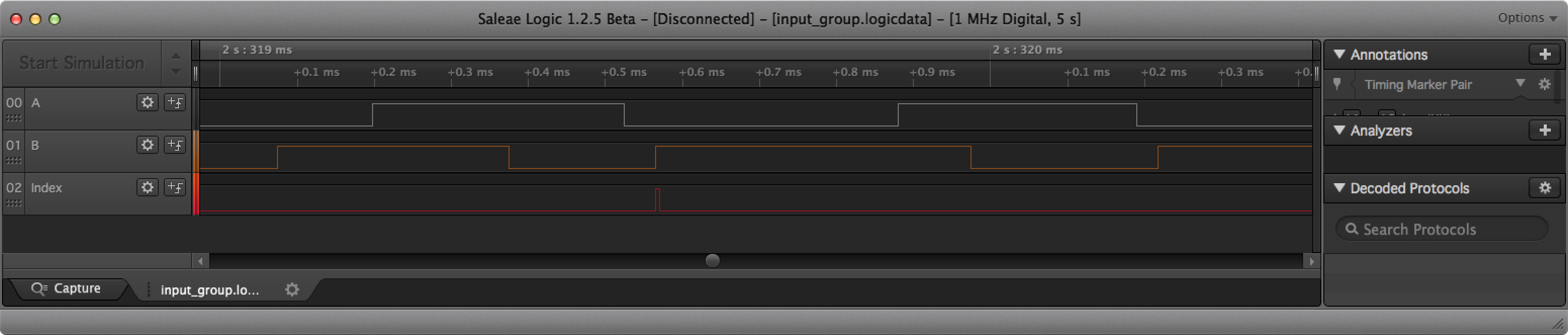
This second part of the sampled data shows catching the index pulse, still moving 'forwards'.
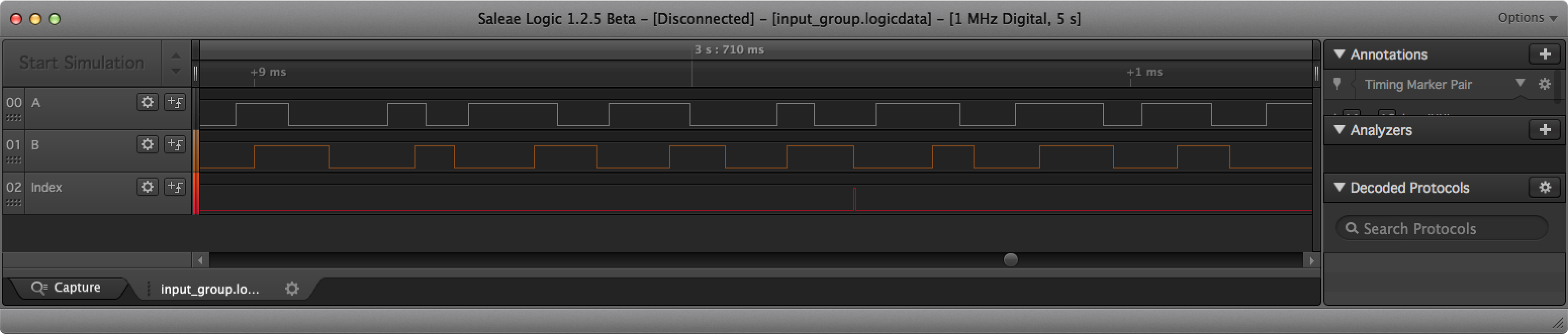
This last batch of data shows moving 'backwards', again catching the index pulse. Not how short the index pulse is - catching it while moving fast will not be fun. Also note that the quadrature output of the Chip is really not 'clean', it seems to really not be at a clean 90 degrees phase angle, and it seems flickery about its speed. We will see how that works out on the motorboards.
Downloads
| Quadrature encoder data from the logic analyser |
Jimena's, Tanja's, Peter's and Lukas's Part:
Sonar Sensor HC-SR04 data on Oscilloscope
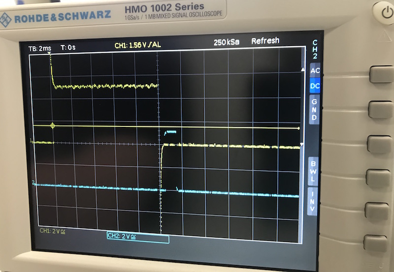
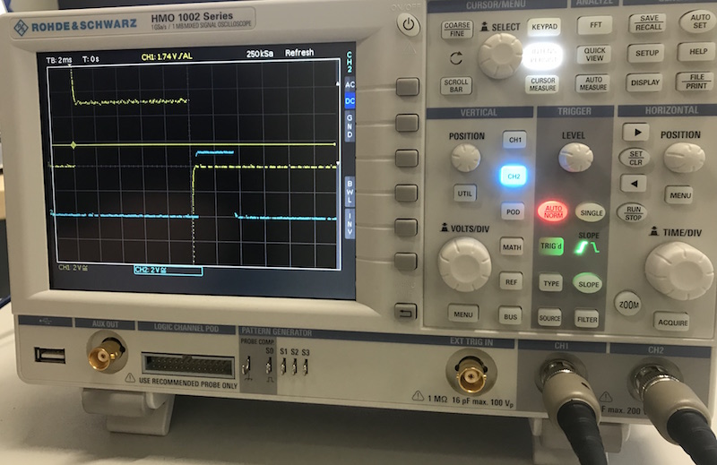
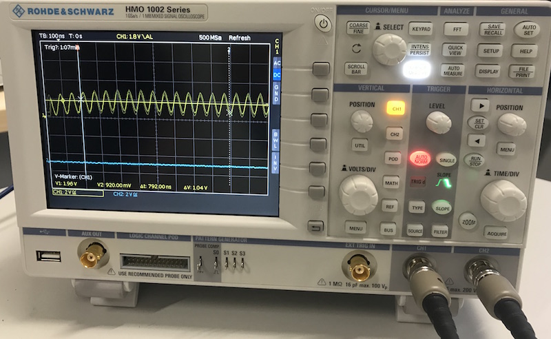
Since we want to display the data of our board and the sensor on an oscilloscope, below are a few pictures showing the data of the HC-SR04.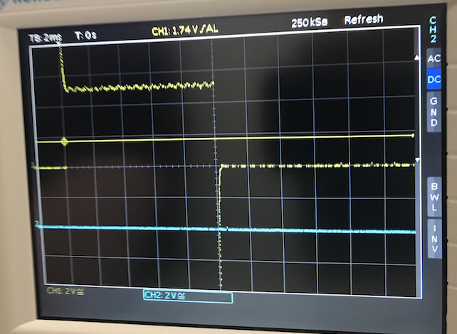
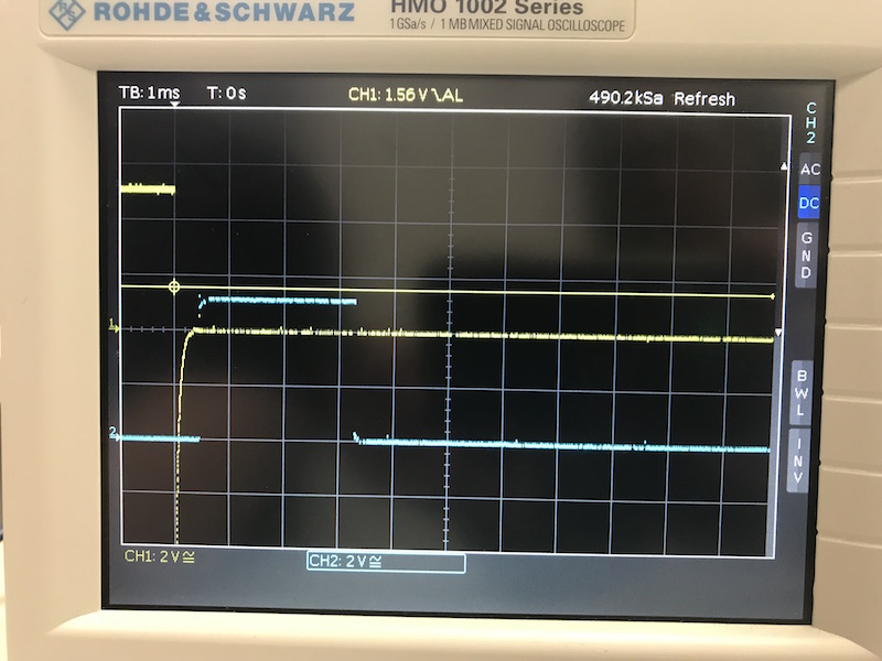
There was no measurement on the first photo and the following three photos show different distances measured by sonar sensor.
The following figure shows a oscilloscope screen shot of the 16 MHz resonator, installed on my board.
measure data transfer with Oscilloscope
One of the biggest pros of a oscilloscope is the possibility of the measurement of high frequency signals. To learn more about the speed of incoming signals we measured a arduino program and a plain C programm so compare the speed of both. We heard that the Arduino language is quite more slowly and so there are often problems with fast signas like for motors. We wanted to see the difference so we used the blinking program and connected the output pin with the oscilloscope.
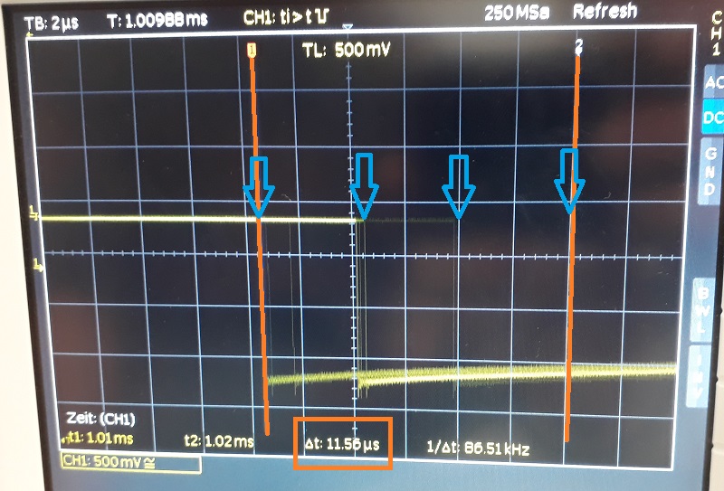
Here you see the voltage jump from high to low of the Arduino program. It jumps between the two orange marks. It is a time span from more than 11.5 uS. So the signal isn´t precise at all. To control a motor or another dynamic system it wont work well. So lets try the same program with C language:
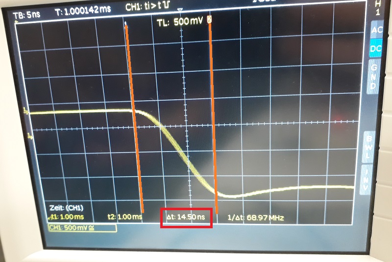
As you see in this picture the jump is quite more precise. I had to zoom in to realize a small flickering. As the orange marks show the complete jump only needs 14.5 nS. So the C language is quite more dynamic. To control a motor the C language will be the better choice.
The test shows that also same working programms could be different in a higher resolution. The oscilloscope is a goot instrument to take a closer look at short or high frequenzy signals.