Output Devices
Task:
- Measure the power consumption of an output device
Daniel's and Christoph's Part:
To accomplish the assignment for this week, we had to measure the energy consumption of an output device.
As my final project board has the option to measure the motor current of my motor, via the VPROPI pin on the DRV8801.
The VPROPI pin offers an analog voltage signal, proportional to the winding current of the motor. The voltage on the pin is five times greater than the winding current of the motor (VPROPI = 5xI). To use the pin and get an meaningful value, a resistor - in my case a 0.2Ω 2W 2512 resistor.
DRV8801 schematic on my final proj board:

The code is quite simple. The first part is to initialize the variables.
                    int motor_direction = 8;                // Motor direction

                    int motor_PWM = 10;                     // Motor PWM

                    int vpropi = A0;                        // VPROPI pin


                    float voltage = 0;                      // VPROPI voltage

                    float current = 0;                      // Motor current

                    float supply = 9.1;                     // Measured with Multimeter

                    float consumption = 0;                   // Power consumption
The next part does the start-up routine on the board, sets the motor direction and initializes the serial connection.
void setup() {
The third part sets the PWM duty cycle, reads the value on the VPROPI pin and sends the data on the serial connection.
pinMode(15,OUTPUT); // Set SysOn PIN as output
digitalWrite(15,HIGH); // Set SysOn HIGH to power PCB
pinMode(motor_direction, OUTPUT); // Set DirectionMOT as output
pinMode(motor_PWM, OUTPUT); // Set PWM_MOT as output
analogReference(INTERNAL);
Serial.begin(9600);
}
                    void loop() {

                    digitalWrite(motor_direction, HIGH);

                    analogWrite(motor_PWM,255);

                    voltage = (float) analogRead(vpropi);

                    current = voltage * 4.881;

                    consumption = supply * current;

                    Serial.print("Current: ");

                    Serial.print(current);

                    Serial.print(" mA  |  Power: ");

                    Serial.print(consumption);

                    Serial.println(" mW");

                    delay(100);

                    }
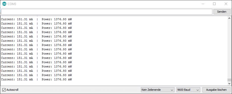
The measured result in milliamps and the calculated milliwatts in the serial monitor.
Downloads
| Program as .ino |
Jimena's, Tanja's, Peter's and Lukas's Part:
We started our Group assignment with the measurement of the power consumption of a small vacuumpump. Therefore we used our multimeter. The pump needs a voltage of 12V so we connected it to a power adapter with an output of 12V. But to get the exact value of the voltage we measured the output additional with our multimeter. Therefore you have to connect it parallel to the consumer. See the result in the picture below.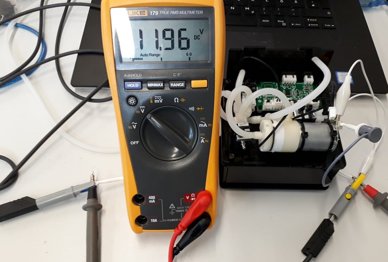
In the next step we liked to measure the amperage of the pump. Therefore you have to change the multimeter setting. In the first stage choose the biggest ampere range you can chose and connect the multimeter in line with the pump. If there are small values you can chance the setting to a better solution to measure smaller amperages. See the final measurement in the picture below:
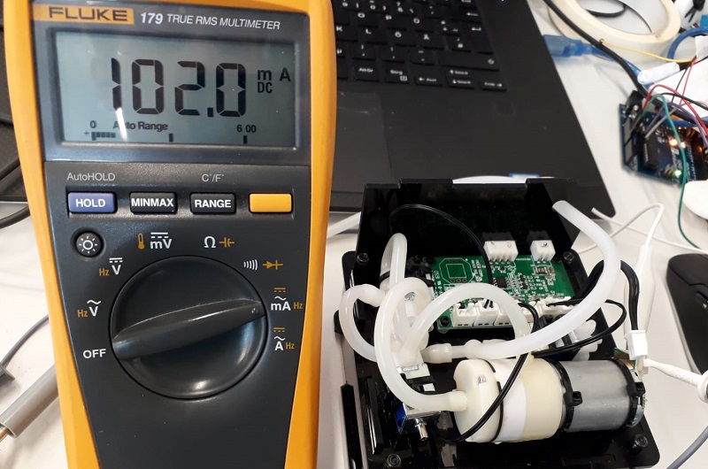
Finally we have to calculate the power consumption. Therefore you have to multiply the amperage with the voltage:
Volt x Ampere = Watt
11.96 x 10²mA = 1,22 Watt
Additional we measured the power consumption of one of our servos. The procedure is the same as with the pump . See the test build below:
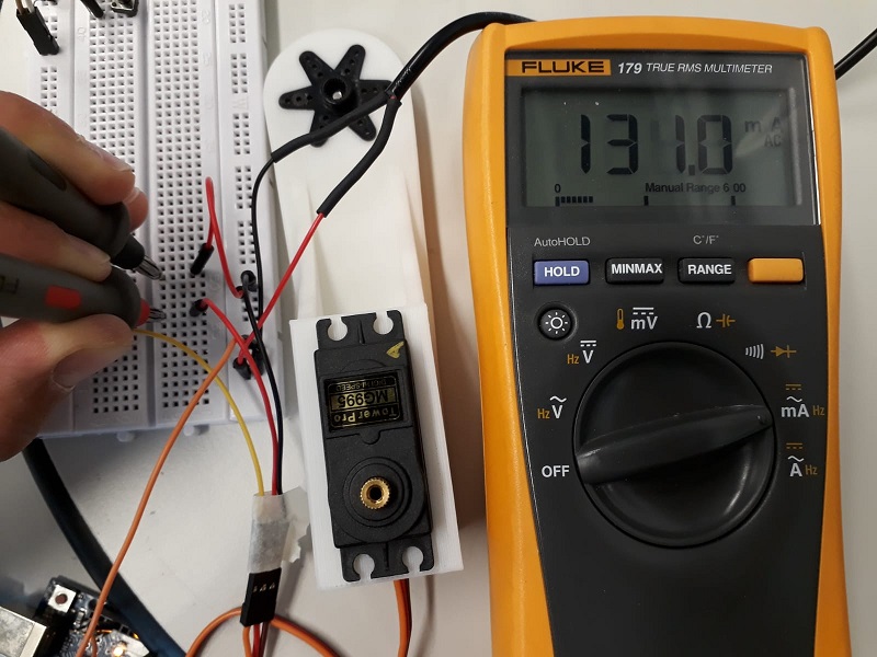
Again the calculation:
11.96 x 131mA = 1,57 Watt
Power supply and measurement of the power consumption with the laboratory power supply device
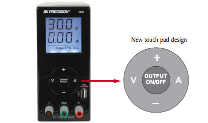
Here you can find the datasheet of the DC bench power supply BK Precision model 1550 with 108 watt power supply (1-36 V and 0-3 A) from
BK Precision.com which I used for powering my Atmega 328p board.

DC Bench
Here I will insert the Introduction for using it from the User Manual of the BK Precision:
"Using the 1550 switching mode power supply
The unit is a Micro-controller based DC power supply with a total supply capability of 108W. By using a
digital + / - keypad operation control, you can set the output voltage and current easily. It is a clean supply
with quiet operation making it ideal for laboratory, work shop or educational applications where work
bench space is limited. The 1550 has a USB charger output, constant current operation, tracking OVP,
floating ground design, small footprint, output on/off push button and a small form factor."
"3.1 Ground Connection
Depending on the application, the power supply output terminals can be grounded in any one of the following
grounding conditions:
Negative ground black (-) negative terminal is shorted with green GND terminal.
Positive ground red (+) positive terminal is shorted with green GND terminal.
Floating ground green terminal is not shorted with any of the output terminals.
Remarks:
When operating this power supply as a floating ground, high impedance leakage can exist between the power
supply circuitry and the chassis ground."
When I connected the board with the three servos to the laboratory power supply, the following reading were to see:
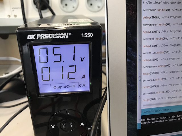
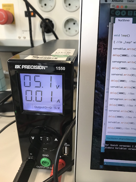
The first image shows the power consumption of the servo start-up phase (the impulse phase is high: 5.1 V and 120 mA). Second image shows the power consumption of the low phase (5.1 V and 10 mA). Here was the servo just turned off (the phase of the pulse was over).