Réseautage et Communications
Task:
- Send a message between two projects
Daniel's and Christoph's Part:
Getting two projects to speak one language
Since Daniel had done Networking in 2016 when we started out, there was only a little to add to his project to get it up to speed for this year. Christoph, on the other paw, never found the time to do this assignment, so the only somewhat doable approach for letting two projects talk to each other was to attach one of his boards into Daniel's network.
As it happened, Christoph's motorboard has two configurable I/O-pins on accessible connectors. They are meant to be inputs for end stops, but that doesn't stop them from being misused for other purposes. The PIC on that board has more or less free assignment of peripherals (like the UART) to individual pins, so using those pins for the UART should work. It turned out that one of those pins is assignable as an input only, but... we only needed one output (for Tx) and one input (for Rx).
The software running on that motorboard is split off from the normal development version, as the UART is not normally needed. It listens to the UART on one of the endstop inputs, and if the incoming bate is addressed to it it switches around its status LED - From off, to red, to green, to blue, to yellow, back to off. Any bytes not addressed to it are forwarded, so in the new network (which is, basically, a ring), any board can talk to any other board. The code for handling incoming bytes is more or less the same as on Daniel's boards.
Of course, we also had to have a look at how it works, so we connected the Logic analyser at the motor board:
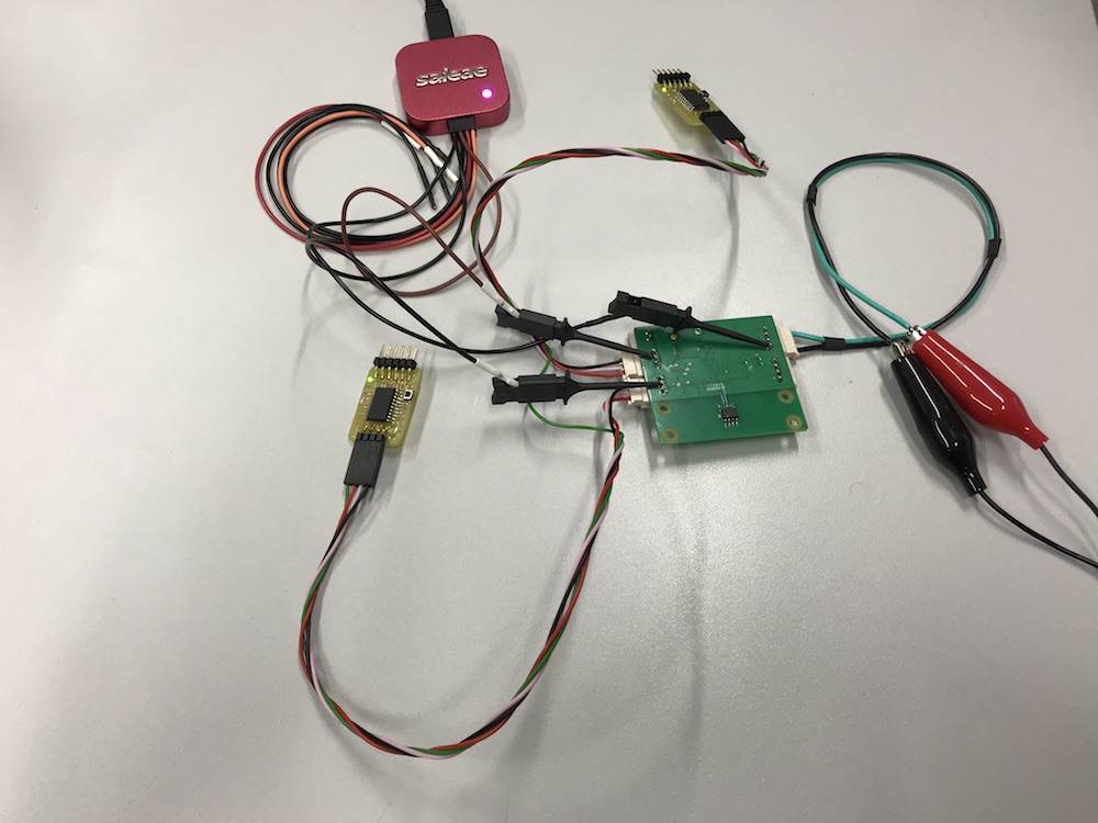
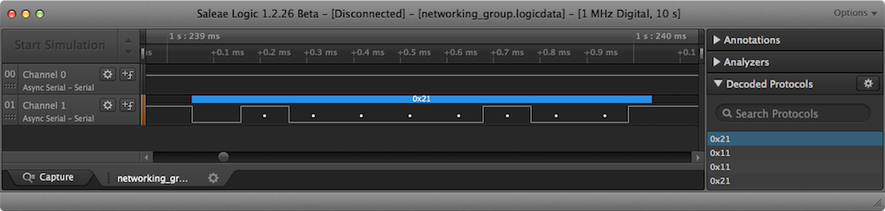
At this point of the ring, there will be packets coming in, and packets being forwarded - There will be no true outgoing packets, given that the motor board has no inputs left to connect a button. An incoming packet is read, but not forwarded (Channel 1 at the bottom is Rx of the board, Channel 0 at the top is Tx):
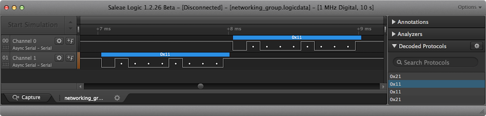
Packets not addressed at the motorboard are immediately forwarded:
Downloads
| Christoph's software project |
| Daniel's software project |
| Logic analyzer data from Daniel's and Christoph's project |
Jimena's, Tanja's, Peter's and Lukas's Part:
Communicate via I2C
I²C (Inter-Itegrated Curcuit) allows to use various masters and various slaves. It was invented by Phlips Semiconductor in the 1990s and needs only two wires (SDA-Data line and SCL-serial clock line). In difference to UART 'Universal Asynchronous serial Receiver and Transmitter' which needs in its bidirectional form TXD, RXD and GND as data lines, the I²C bus drivers are 'open drain'. That means that the connection lines have to be pulled down for a signal from 1 to 0. The lines uses 5V and waiting for transmitting a signal. For sending a signal the closed lines gets opened and pulled town to 0. The clock regulation allows the slave to hold the 0 for a while to extend the communication. This connection works only with small distances. I²C is usable without any license fees for a lot of applications since 2006. See here a scheme of the transmitting process:
For additional info we used the I²C-bus specification and user manual you find in the download section. We also used some Youtube-Videos to understand the process and learn more about some examples.
So we started wiring with two Arduinos. We had in this week some trouble with our milling machine so we was not able to build another self developed board. We wanted to start with a quite simple program: control the LED-brightness with the potentiometer via I²C. As you see in the picture we connected the necessary SCL and SDA line but also the VCC and GND. VCC wouldn´t be necessary (we show it later again with a external voltage source), but for a good connection both boards should use the same GND. The wiring of the potentiometer and a LED we showed a few weeks ago so we don’t reply it.
Couse we used the Arduino IDE we are able to use a library which allows a quite simple connection. See our commented program below:
Master Code LED
#include <Wire.h>  //include library

int potPin = A0;   //integrate pin for potentiometer

byte sendData=0;    //add a byte with the name 'sendData'


void setup() {
 Wire.begin();       //start the library

}

void loop() {

sendData = map(analogRead(potPin),0,1023,0,255);  //set 'sendData' to the analog input of the potentiometer and map it to a value between 0 and 255

Wire.beginTransmission(4);  //choosen Slaveadress besides 0,1,2,3 and 120-127 and begin transmission
Wire.write(sendData);        //send the 'sendData' byte
Wire.endTransmission();      //end transmission

delay(50);                   //delay of 50 ms
}
Slave Code LED
#include <Wire.h>        //iclude library

byte incomeData=0;        //integrate a byte named 'incomeData'
int ledPin = 9;            //set the LED pin

void setup() {
pinMode(ledPin, OUTPUT);            //set the led pin as a output pin
Wire.onReceive(receiveEvent);        //receiving the Data
Wire.begin(4);                       //begin the communication and set the slave adress to 4 (the same as in the master program)

}

void loop() {
delay(50);                    //delay of 50 ms
}

void receiveEvent(int howMany)           //descripe the function 'receiveEvent'
{
incomeData = Wire.read();                  //set the incomming signals to the 'incomeData' byte
analogWrite(ledPin, incomeData);            //set the vaule of 'incomeData' as the analog output of the led pin
}
After checking the program we used our self developed boards for the communication. The build is completely equal, we had only to use the right pins of our boards.

See here the working boards:
Communicate via Laser
We have written a program to communicate via a laser.
The protocol:
The basic idea is that the laser is always on but then interrupted for a fixed time.
The time between two pulses is measured and based on the time decisions are met.
There are four cases (times).
- LOW
- HIGH
- New character
- New line
New character will be transmitted then follow 8 bits (LOW/HIGH) from the character.
New Line is transmitted at the end of the line.
We writte for testing the RX and the TX part on the same controler.
Below are the the complete code.
In the loop () is the TX part in the interrupt function is the RX part.
The Program:
boolean state = false;
boolean valid = false;
boolean new_ = false;
boolean newline = false;

unsigned long time_stop;
int pulse_time;

int time_pulse = 3;
int time_on = 10;
int time_off = 15;
int time_new = 20;
int time_newline = 25;

int time_diff = 2;

boolean RX_buffer[8];
char RX_char;
int buffer_counter;

//------TX------
const int message_len = 12;
char inputChar[message_len] = "Hello World!";


void setup() {
Serial.begin(9600);
pinMode(4, OUTPUT);
pinMode(2, INPUT_PULLUP);
attachInterrupt(digitalPinToInterrupt(2), stop_time, FALLING);
}

int x = 0;
void loop() {

  digitalWrite(4, HIGH);
  delay(time_new);
  digitalWrite(4, LOW);
  delay(time_pulse);

  for ( uint8_t bitMask = 128; bitMask != 0; bitMask = bitMask >> 1 ) {
    digitalWrite(4, HIGH);
    if ( inputChar[x] & bitMask ) {
      delay(time_on);
    } else {
      delay(time_off);
    }
    digitalWrite(4, LOW);
    delay(time_pulse);
  }
  x++;
  if(x > message_len){
    x=0;
    digitalWrite(4, HIGH);
    delay(time_newline);
    digitalWrite(4, LOW);
    delay(time_pulse);
  }
}

void stop_time(){

    pulse_time = millis() - time_stop;
    if(pulse_time > time_diff){
       valid = false;
       new_ = false;
       newline = false;
       if(pulse_time <= time_on + time_diff && pulse_time >= time_on - time_diff)state = true, valid = true;
       if(pulse_time <= time_off + time_diff && pulse_time >= time_off - time_diff)state = false, valid = true;
       if(pulse_time <= time_new + time_diff && pulse_time >= time_new - time_diff)new_ = true;
       if(pulse_time <= time_newline + time_diff && pulse_time >= time_newline - time_diff)newline = true;

       if(valid){
         if(buffer_counter > 8)buffer_counter = 0;
         RX_buffer[buffer_counter] = state;
         buffer_counter++;
       }

       if(new_){
        RX_char = 0;
        for(int i = 0; i<8;i++){
          RX_char |= RX_buffer[7-i] << i;
        }
        Serial.print(RX_char);
        buffer_counter = 0;
       }

       if(newline){
        Serial.println("");
       }
    }
    time_stop = millis();
}
In the video you can see how how we transfer data between our boards.
Downloads
| Download Transfair (RX and TX on the same board)(zip) | download |
| Download RX Code(zip) | download |
| Download TX Code(zip) | download |