| Position | Piece | Price (€) | 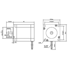
|
|
|
|||||||||||||||||||||||
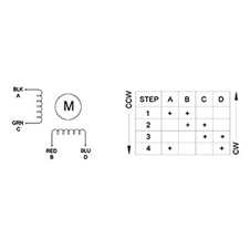
| 1 | ROSENICE Nema 23 Stepper Motor | 2 | 24,99 | |||||||||||||||||||||||||
| Bipolar 2.8A 178.5oz.in 1.26Nm | ||||||||||||||||||||||||||||
| Product | ||||||||||||||||||||||||||||
|
||||||||||||||||||||||||||||
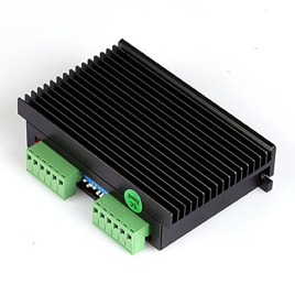
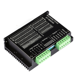
| 2 | SainSmart CNC Mikroschr Ittsc Hritt Stepper Motor Driver | 2 | 39,99 | |||||||||||||||||||||||||
| 2 M542 Two-Pin 2 Phase Switch 4.2 A | ||||||||||||||||||||||||||||
| a href=" Product ; | ||||||||||||||||||||||||||||
|
||||||||||||||||||||||||||||
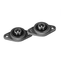
| 3 | Sienoc 8 mm Hole Inner Ball Mounted Pillow Block Ball Bearing | 3 | 7 | |||||||||||||||||||||||||
| Insert Bearing Pillow Block Ball Bearing | ||||||||||||||||||||||||||||
| a href=" Product | ||||||||||||||||||||||||||||
|
|
|||||||||||||||||||||||||||
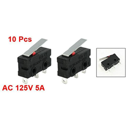
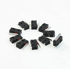
| 4 | Winomo Premium 125 V AC 5 Amp SPDT 1NC 1NO | 2 | 4,99 | |||||||||||||||||||||||||
| Short Straight Hinge Lever Mini Micro Switch Ð Pack of 10 | ||||||||||||||||||||||||||||
| a href=" Product | ||||||||||||||||||||||||||||
|
||||||||||||||||||||||||||||
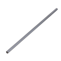
| 5 | BQLZR Silber Cylinder Liner Schienen lineare Wellen | 2 | 6,78 | |||||||||||||||||||||||||
| optischen Achse OD 8mm x 300mm Kartelle | ||||||||||||||||||||||||||||
| a href=" Product | ||||||||||||||||||||||||||||
|
||||||||||||||||||||||||||||
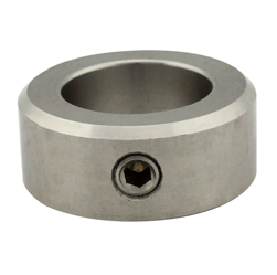
| 6 | DIN 705 Form A, with Grub Screw Pack of 10 Screw Collars | 2 | 12,1 | |||||||||||||||||||||||||
| (DIN 914)Ð A2 Stainless Steel (V2 A) SC Standard Part | ||||||||||||||||||||||||||||
| Product | ||||||||||||||||||||||||||||
| Maker Beam Parts | |||||||||||||||||||||||||
| Position | Length (mm) | Pieces | Price (€) | Pieces per Package | |||||||||||||||||||||
|
|||||||||||||||||||||||||
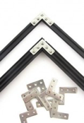
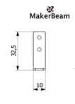
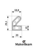
| 1 | Right angle brackets | 16 | 6,96 | 12 |
|
||||||||||||||||||||
| Product | |||||||||||||||||||||||||
|
|||||||||||||||||||||||||
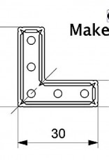
| 2 | Corner Brackets | 4 | 6,96 | 12 | |||||||||||||||||||||
| Product | |||||||||||||||||||||||||
|
|
||||||||||||||||||||||||
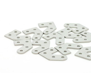
| 3 | 45 degree brackets | 10 | 6,95 | 12 | |||||||||||||||||||||
| Product | |||||||||||||||||||||||||
|
|||||||||||||||||||||||||
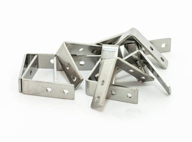
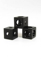
| 4 | Corner Cube black | 18 | 14,95 | 12 | |||||||||||||||||||||
| Product | |||||||||||||||||||||||||
|
|||||||||||||||||||||||||
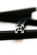
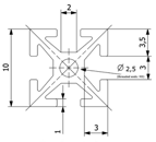
| 5 | 10x10 mm Profile, black | 200 | 11 | 12,25 | 8 | ||||||||||||||||||||
| Product | |||||||||||||||||||||||||
| 6 | 10x10 mm Profile, black | 150 | 7 | 12,25 | 8 | ||||||||||||||||||||
| 7 | 10x10 mm Profile, black | 110 | 1 | 12,25 | 8 | ||||||||||||||||||||
| 8 | 10x10 mm Profile, black | 100 | 1 | 12,25 | 8 | ||||||||||||||||||||
| 9 | 10x10 mm Profile, black | 40 | 16 | 12,25 | 8 | ||||||||||||||||||||
|
|||||||||||||||||||||||||
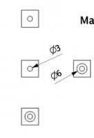
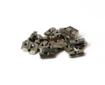
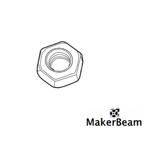
| 10 | T-slot nuts M3, 4 mm | 30 | 14,25 | 25 | |||||||||||||||||||||
| Product | |||||||||||||||||||||||||
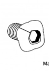
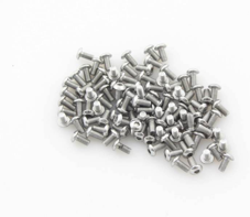
| 11 | Square headed bolts with hex | 88 | 13,85 | 250 |
|
|
|||||||||||||||||||
| hole, M3, 6 m | |||||||||||||||||||||||||
| Product | |||||||||||||||||||||||||
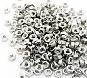
| 12 | M3 regular nuts | 88 | 4,5 | 250 |
|
||||||||||||||||||||
| Product | |||||||||||||||||||||||||
|
|||||||||||||||||||||||||
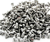
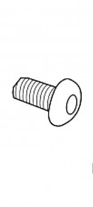
| 13 | Button head socket bolt | 30 | 6,5 | 100 | |||||||||||||||||||||
| M3, 6 mm | |||||||||||||||||||||||||
| Product | |||||||||||||||||||||||||
Scara Accessory Part List
| Position | Pices | Length (mm) | |
| 1 | Arduino gnuino Uno | 1 | |
| 2 | Arduino Motor Shield | 1 | |
| 3 | Banana plug connector | 2 | |
| 4 | Cable, high voltage and current | 12 | 400 |
| 5 | Cable, low voltage and current | 12 | 400 |
| 6 | Cable tie | 20 | |
| 7 | Tube piece | 4 | 140 |
| 8 | Bearing for tool joint | 1 | |
| 9 | Bearing for elbow joint | 4 | |
| 10 | Rivet | 8 | |
| 11 | Pen | 1 | |
| 12 | Bolt for Hinge Lever Mini Micro Switch | 4 | |
| 13 | Bolt for inner joint | 4 | |
| 14 | Bolt for coupling | 4 | |
| 15 | Nut for coupling | 4 | |
| 16 | Bolt for banana plug connector | 4 | |
| 17 | Nut for banana plug connector | 4 |
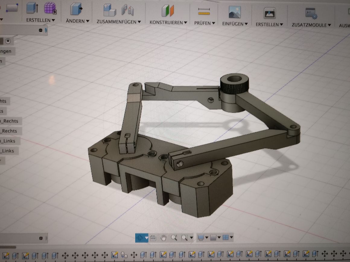
Scara 3D Print Parts List
| Position | 3D Parts | Piece | Colour |
| 1 | Motor mount | 2 | white |
| 2 | Arduino mounting | 1 | white |
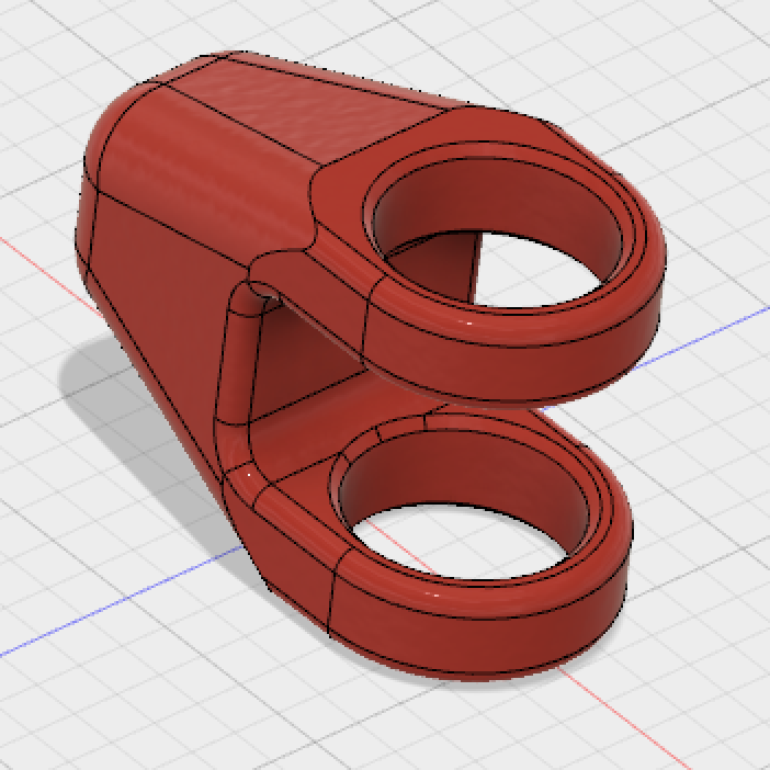
| 3 | Hinge Lever Mini Micro Switch housing | 2 | red |
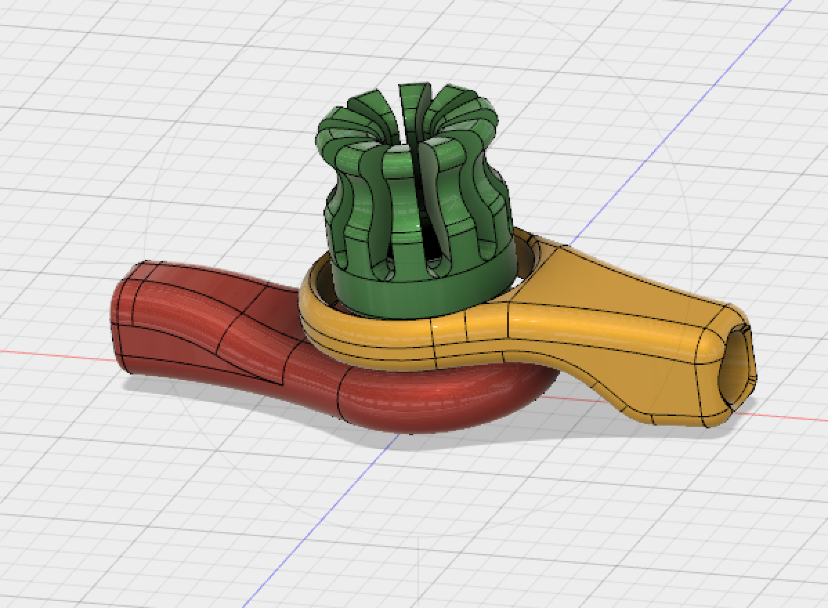
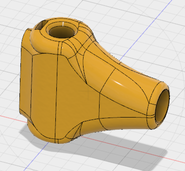
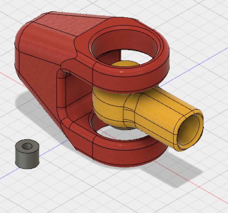
| 4 | Outer joint | 2 | red-white |
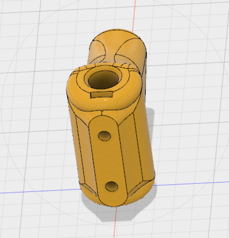
| 5 | Inner joint | 2 | 1xred, 1xwhite |
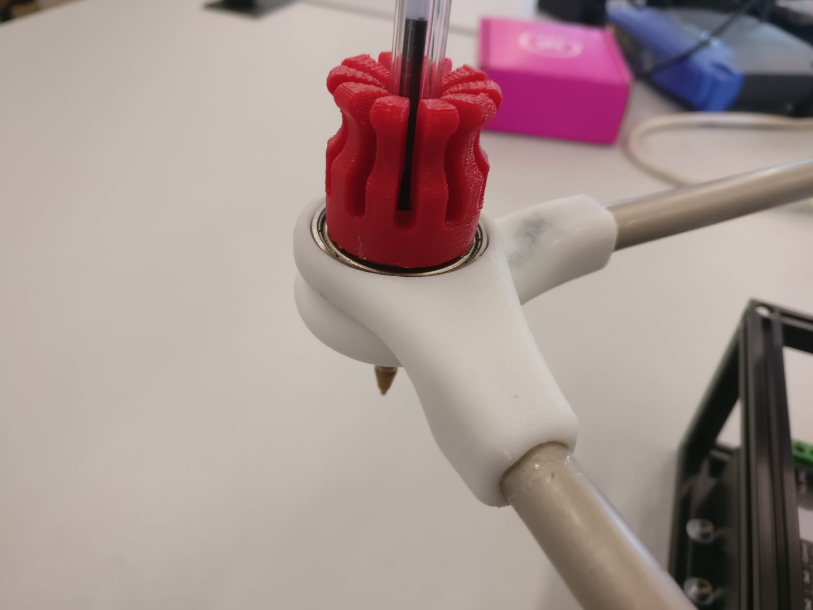
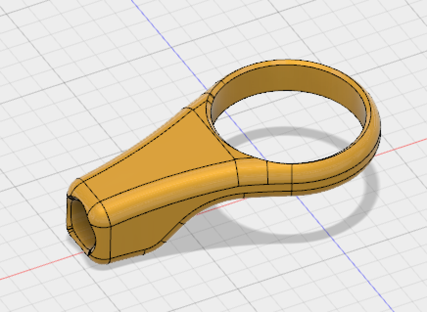
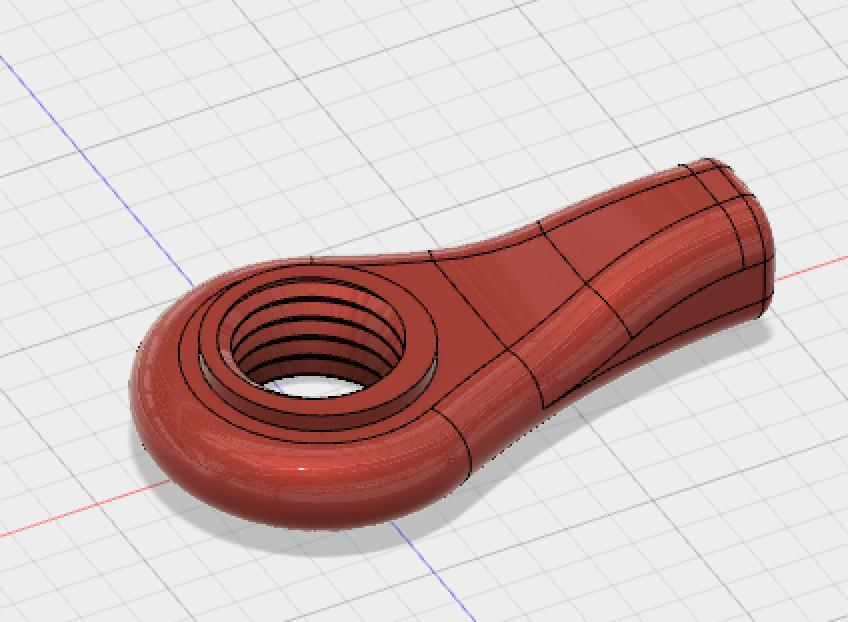
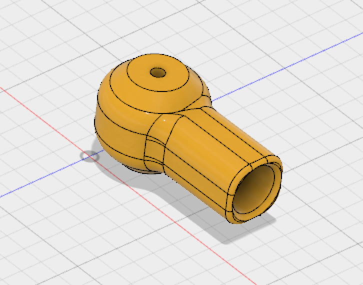
| 6 | Tool joint | 2 | white |
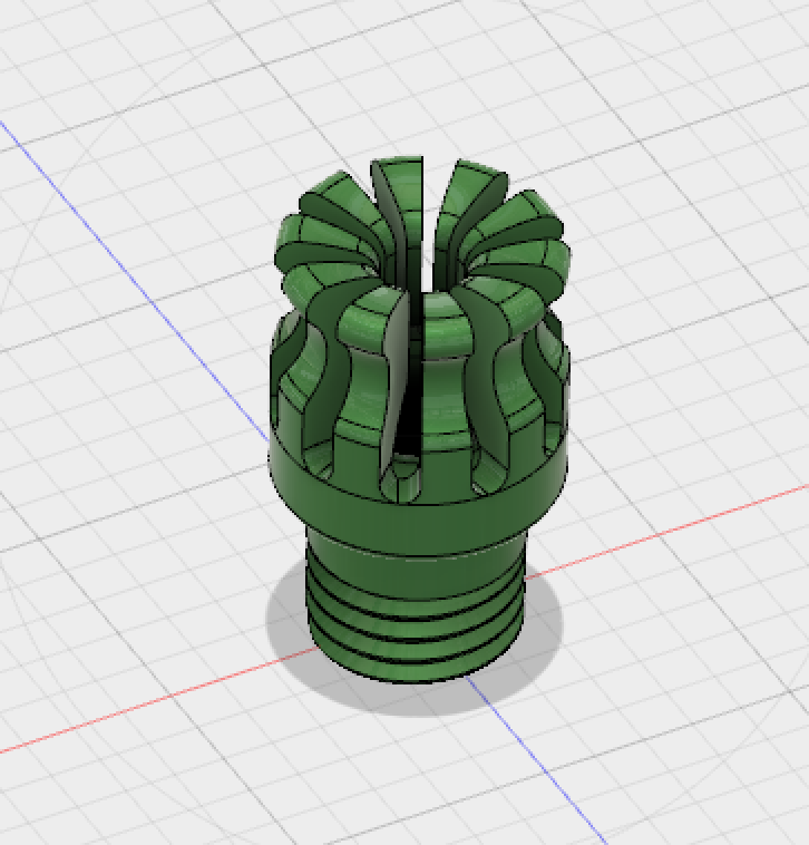
| 7 | Tool mounting | 1 | red |
| 8 | Coupling | 2 | red |
ACTUATE AND AUTOMATE THE SCARA-DRAW-BOT:
Input: Interface, Canvas, SVG, GCode
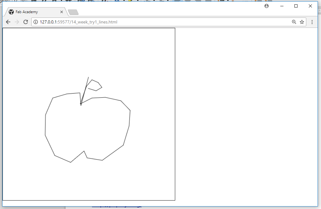
Originally we had the idea to use the Canvas Interface (Java) for the Scara-Draw-Bot. The drawing on the Canvas can be downloaded and saved as an SVG File.
The next step was to load the SVG Drawing in Inkscape and to generate a GCode with a plugin in Inkscape. To control the machine we also need a GCode-Interpreter. These are the steps:
SOFTWARE CHAIN
→ (1) Generate a Raster or SVG File → with the Canvas Interface
→ (2) Generate the GCode from (1) → With a plugin in Inkscape
→ (3) Send the GCode to the Arduino board → with a GUI
→ (4) Transform the GCode into movements → with a GCode Interpreter
Generating the interface and the SVG file
First Script
Here are some basics I read about HTML Canvas: Link HTML Canvas
The next step was to generate vectors (lines) on the canvas. The script is based on this tutorial: JavaScript Tutorial – To draw a line with a mouse click | Canvas Click Event
To understand the JavaScript I read about these terms
DOM: Document object Model ist a an interface that allows scripts to dynamically access and update content, structure and style.
- JS DOM Elements: getElementById
- JS DOM EventListener: addEventListener
and found this link very useful: Link JS HTML DOM
LINK TO THE HTML SITE "Drawing lines (vectors) on Canvas"
Second Script
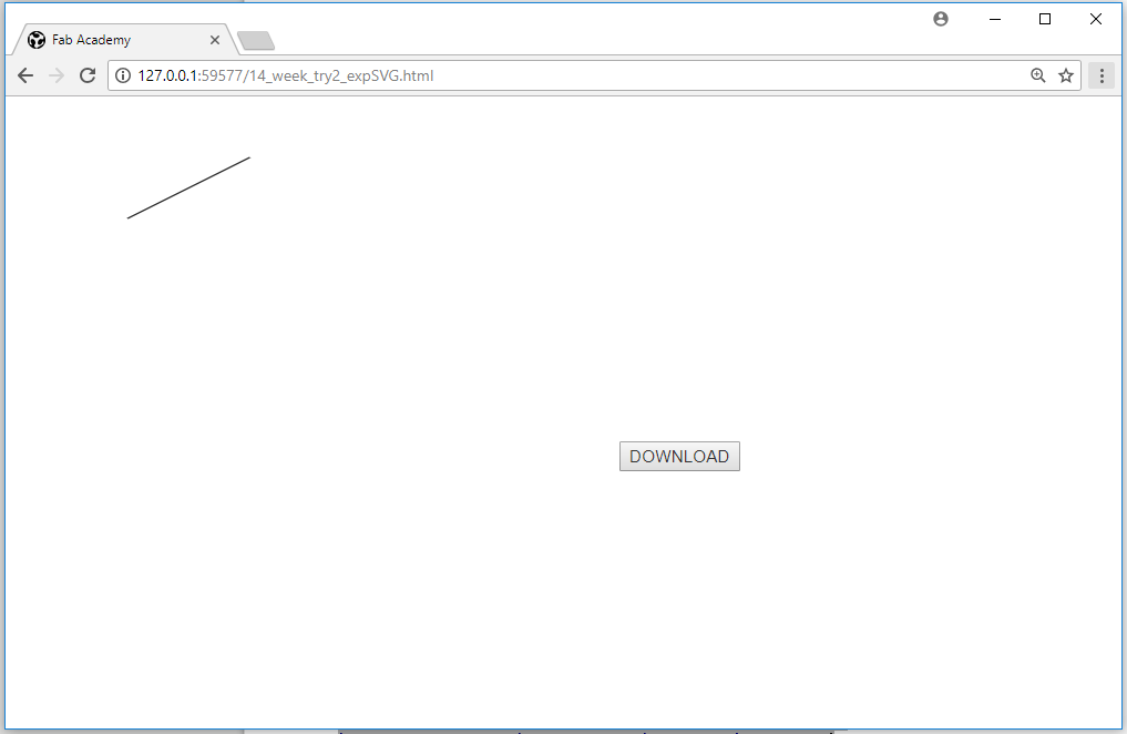
We wanted to export the vectors as an SVG file. The following script only exports what is described in the script, that’s why we couldn’t use the code of this tutorial for our purpose.
Tutorial: Draw with JavaScript and Export to SVG with PAPER.JS
LINK TO THE HTML SITE "Using paper.js | Exporting SVG file"
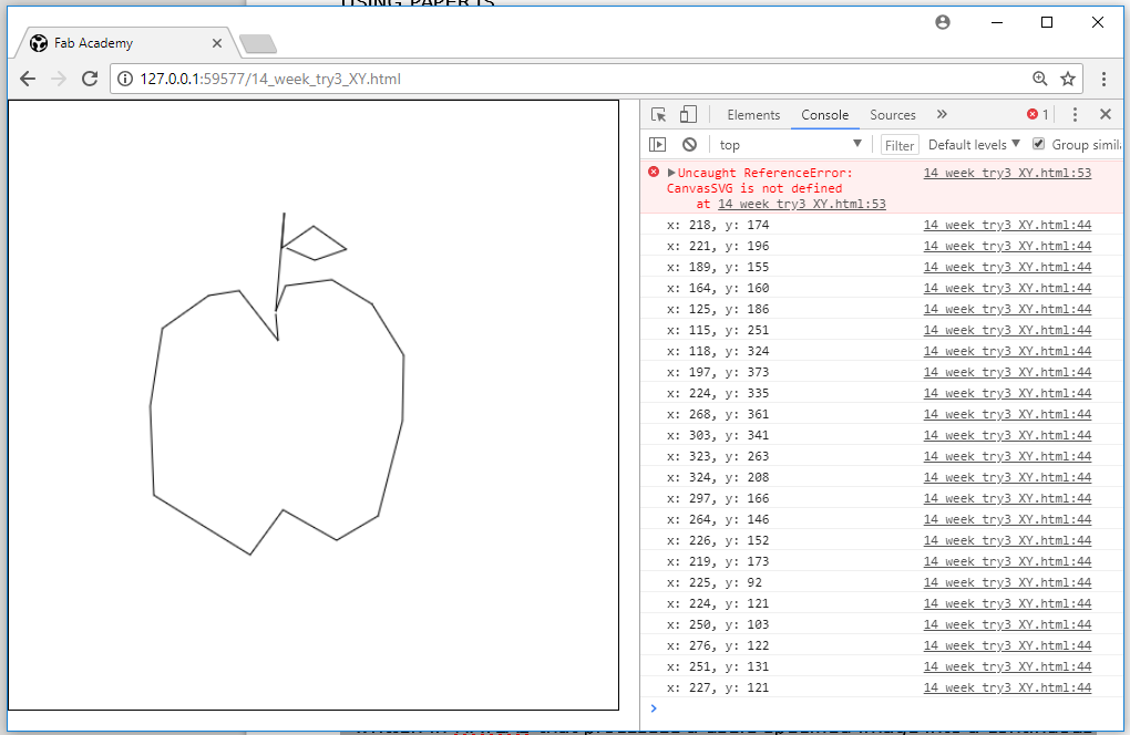
Third Script
The next step we wanted to try was to get the X and Y coordinates from the mouse click on the canvas.
We checked this site...Get the mouse coordinates when clicking on canvas
… and then I combined the script with the FIRST TRY. So you can draw the lines (vectors) and get the XY coordinates. To see the coordinates: Press F12 and then go to Console.
LINK TO THE HTML SITE "Using paper.js | Exporting SVG file"
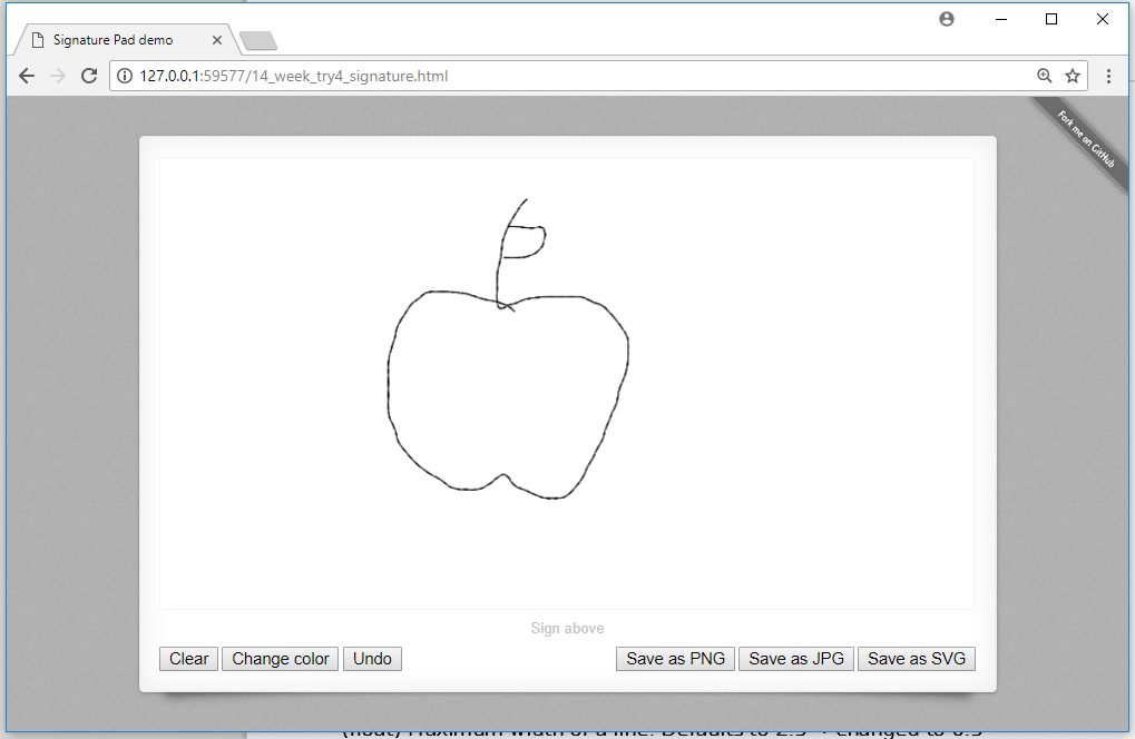
Fourth Script
Finally, I found a JS script to generate vectors on a canvas and download them. You also can download JPG or PNG files. Take a look at the Github Site: Link signature_pad
The author of the script explained also, that you can change some options in the file signature_pad.umd.js, for example:
- Row 181: maxWidth
(float) Maximum width of a line. Defaults to 2.5
→ I changed it to 0.5
or
- Row 182: throttle
(integer) Draw the next point at most once per every x milliseconds. Set it to 0 to turn off throttling. Defaults to 16.
→ I changed the value to 50 milliseconds.
LINK TO THE HTML SITE "Using paper.js | Exporting SVG file"
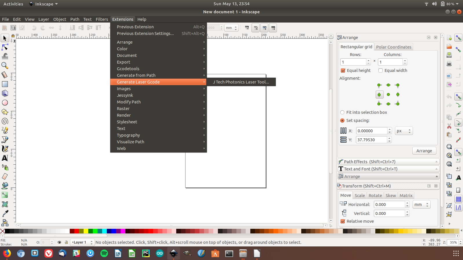
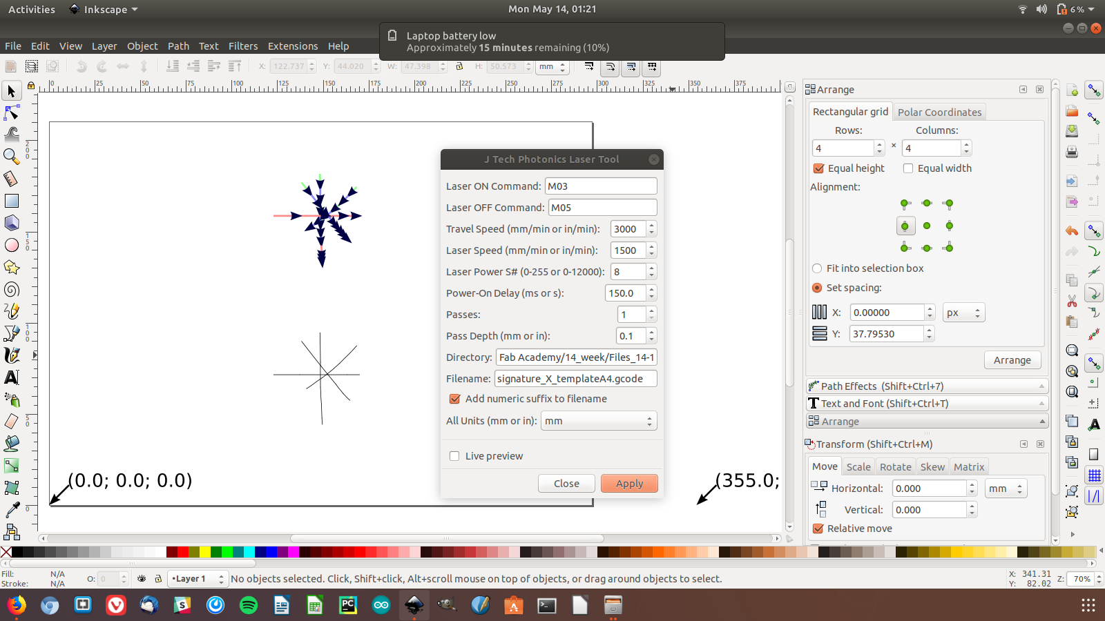
Generating the Gcode with a SVG file | Inkscape Extensions
Many drawing machines utilize a series of Inkscape extensions to control the machine. Inkscape is open source and has a python plugin system.
We wanted to use a GCode Interpreter (for example GRBL) to control the machine. For that I search for an Inkscape Extension to generate a GCode.
In some tutorials about drawing robots, the author mentioned this plugin:
JTP Laser Tool Plug-In for Inkscape | Tutorial Crazy Engineer’s Drawing Robot
A GCode is a programming language to control computerized machine tools. The machine moves according the g-codes. These “tells” the machine controller how to move the motors, the speed and the path. Link What is a G-code
HOW TO INSTALL THE EXTENSION (PLUG-IN) JTO Laser Tool
- Download the zip file from the Website JTO Laser Tool and extract it.
Download JTO laser Tool linked above.
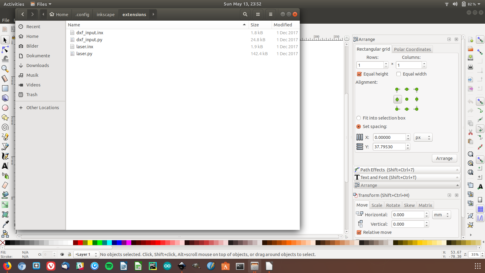
- Move the unzipped files into this folder in the installation directory:
- In Windows: > inkscape/share/extensions
- In Ubuntu: > home/.config/inkscape/extensions
You find more information about Inkscape Extensions here: Link Inkscape Extensions Gallery
NOTE
After many tries to control the machine with the GCode, it didn’t work.
That’s why we decided to start from the scratch and try another way to control the machine with a new script.You can see the result on the video.
You find more information about the new script on the bottom of this page.
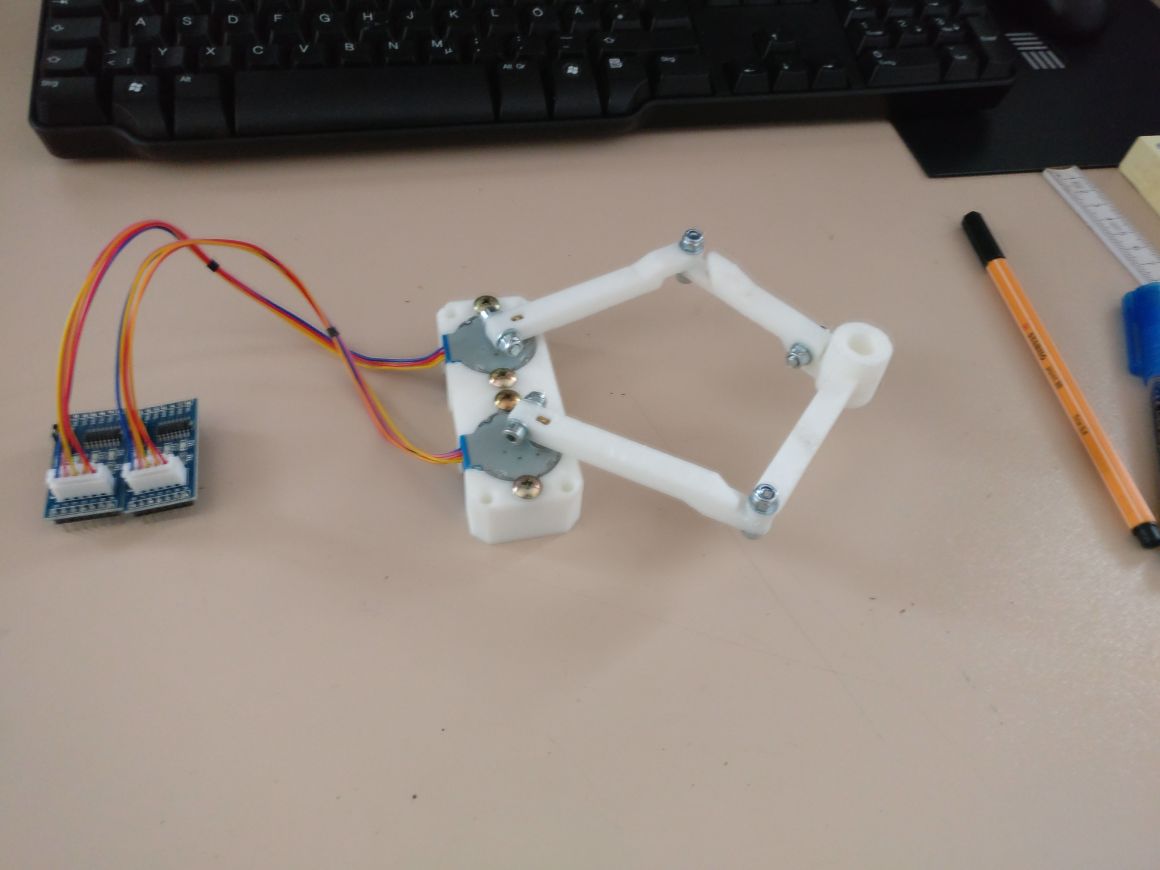
MAKING THE ROBOT MOVE
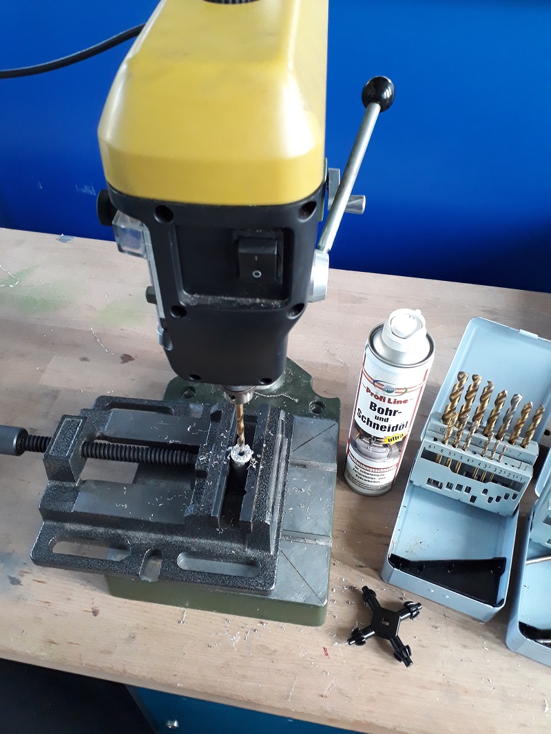
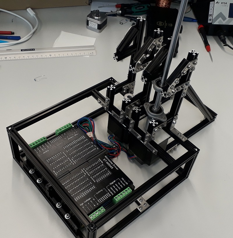
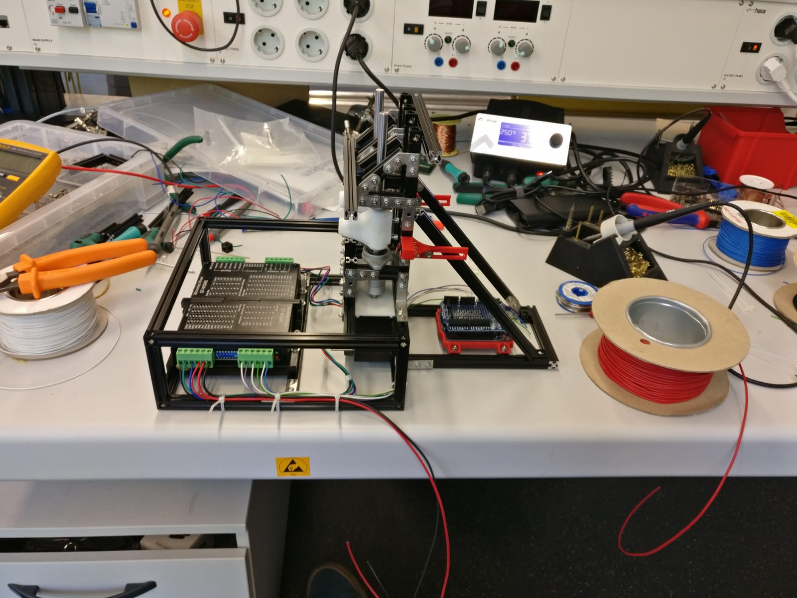
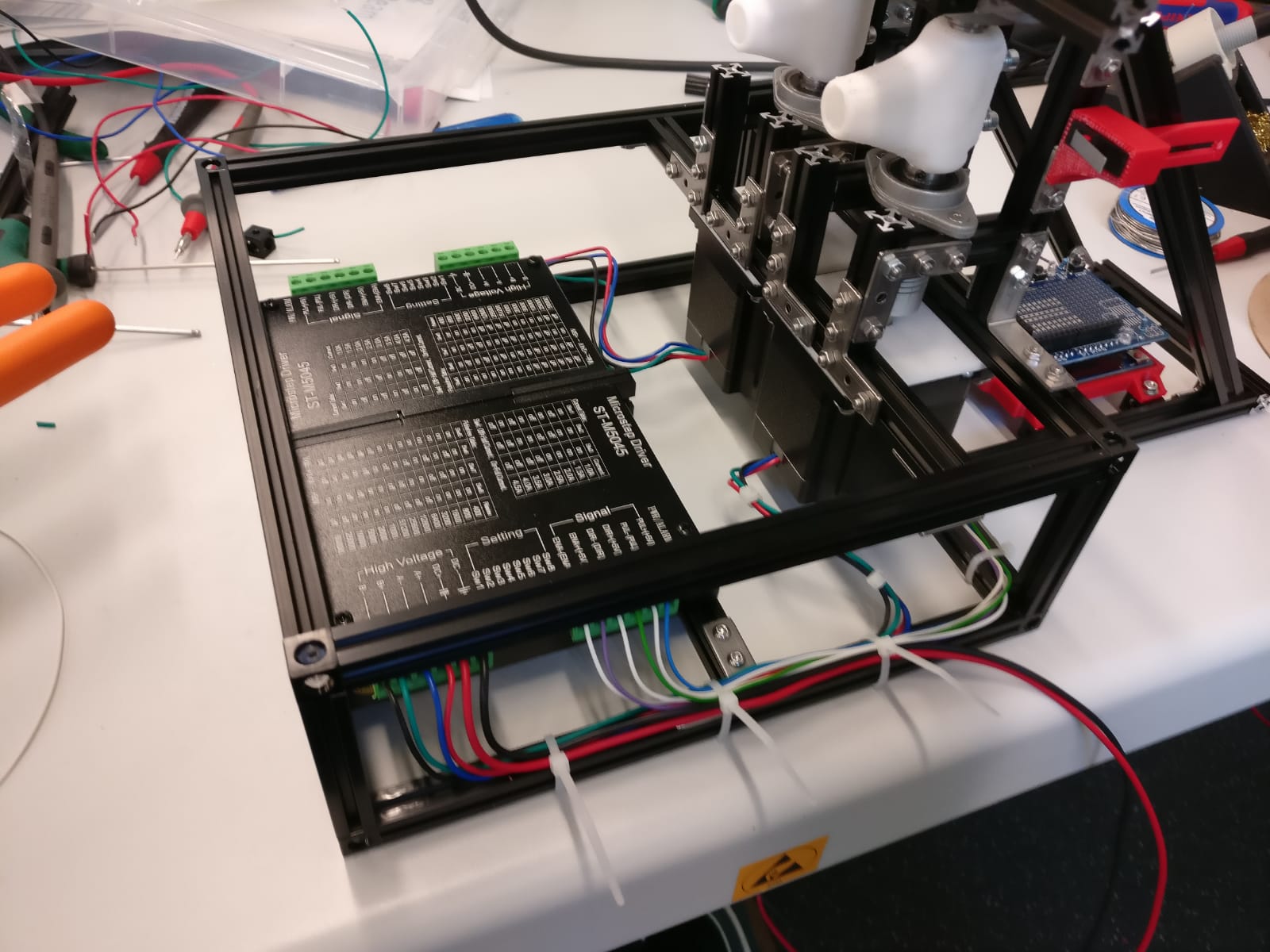
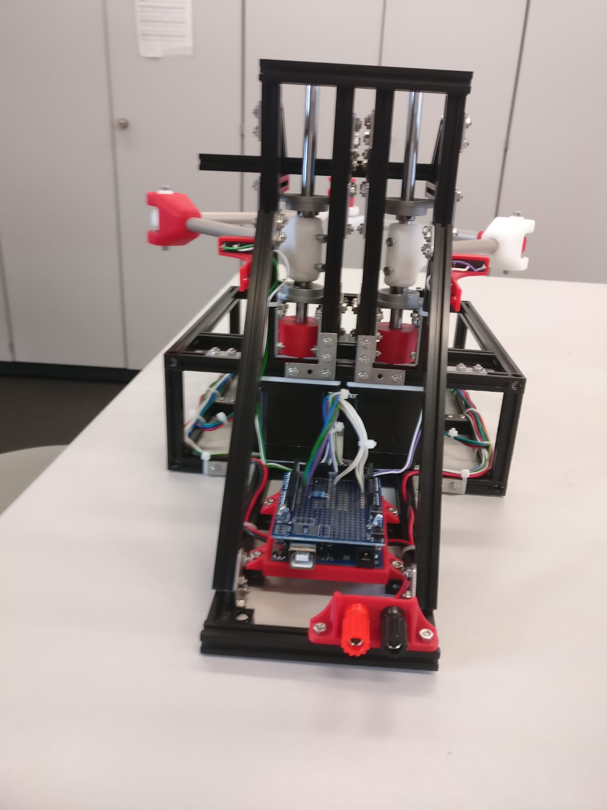
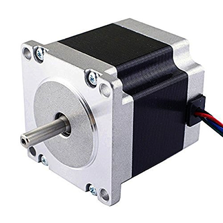
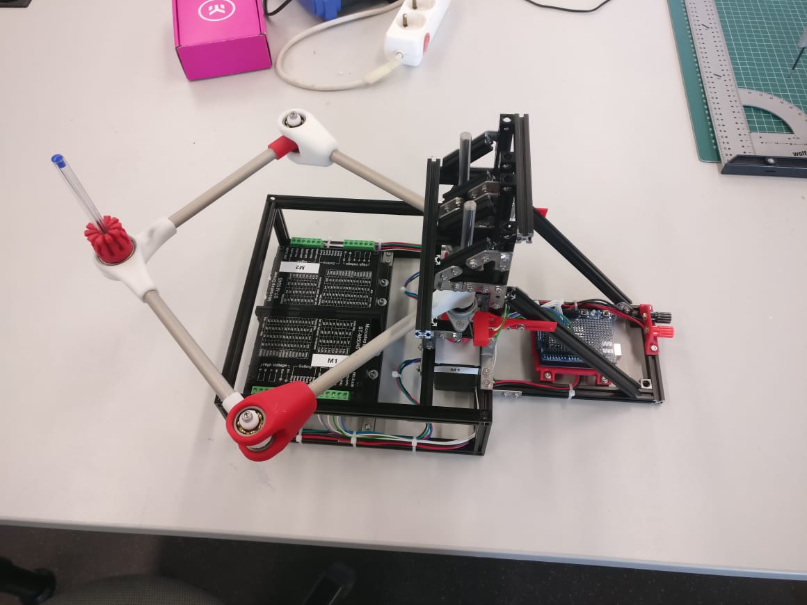
In this part of the assignment we wanted to make our robot move. Therefore we chose two Nema 23 stepper motors because they are big enough to handle even big arms. Before connecting them to our frame we tested them out to check their controlling options. See below our test station.

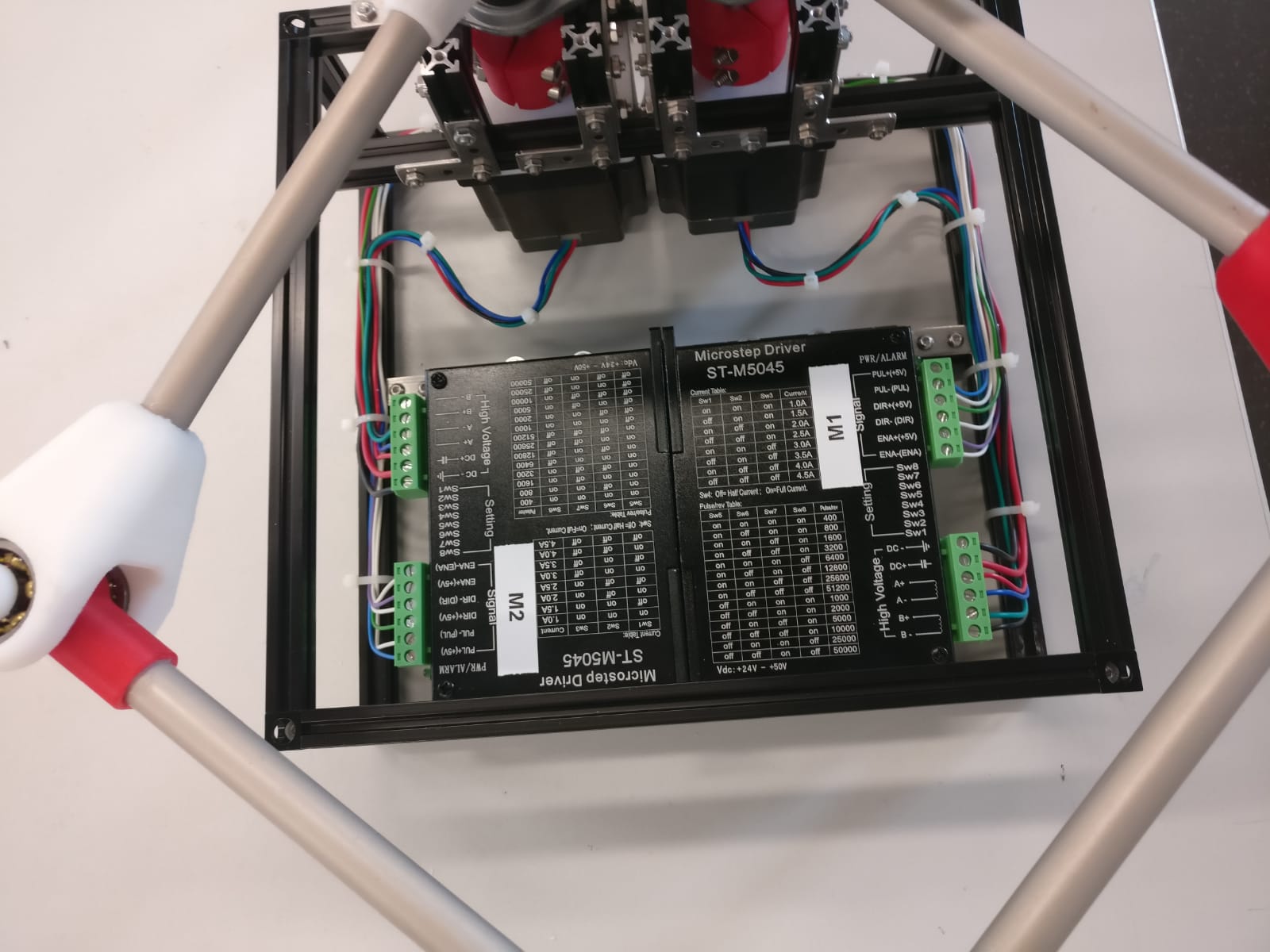
First we tried out some settings at our motor and the additional microstep driver. With this you can handle 200 to 50.000 steps per round and set the power of the motor up to 4.5 ampere. Find below the Arduino program with a simple direction change after 1600 steps.
int i=0;
boolean dir=false; //direction controll
void setup()
{
pinMode(2, OUTPUT); //power
pinMode(3, OUTPUT); //direction
pinMode(4, OUTPUT); //step signals
digitalWrite(2, HIGH);
digitalWrite(3, LOW);
}
void loop()
{
i++;
digitalWrite(4, LOW);
delayMicroseconds(1);
digitalWrite(4, HIGH);
delayMicroseconds(1000);
if(i>1600){
i=0;
if(dir) //change direction after 1600 steps
{
dir=false;
digitalWrite(3, LOW);
}
else {
dir=true;
digitalWrite(3, HIGH);
}
}
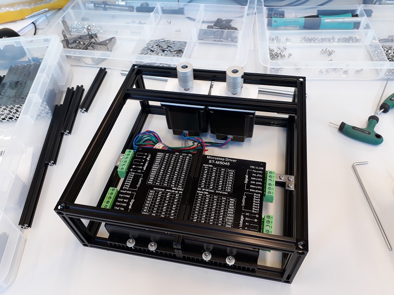
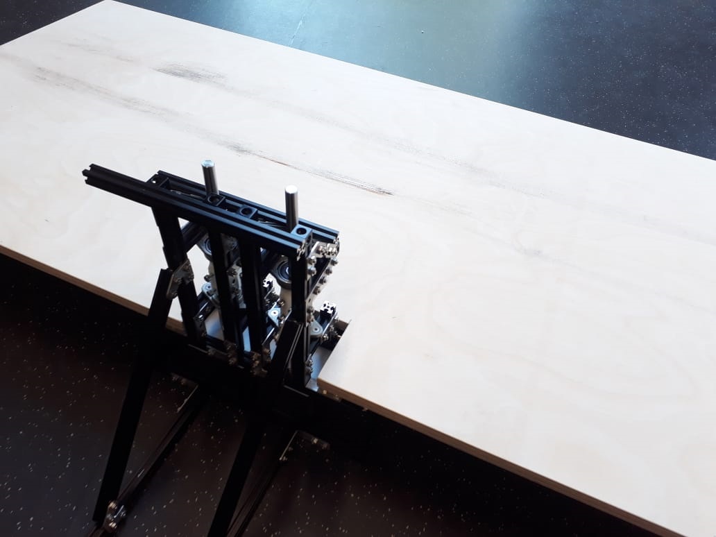
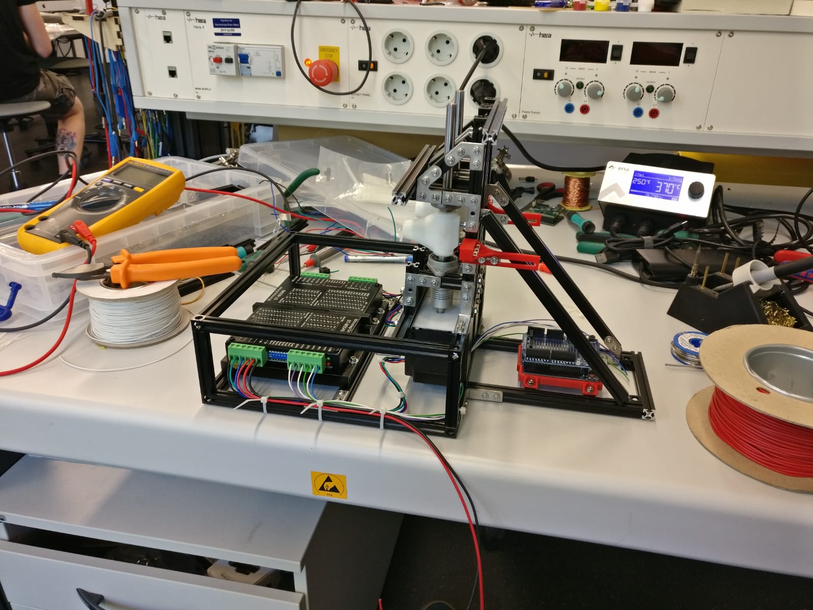
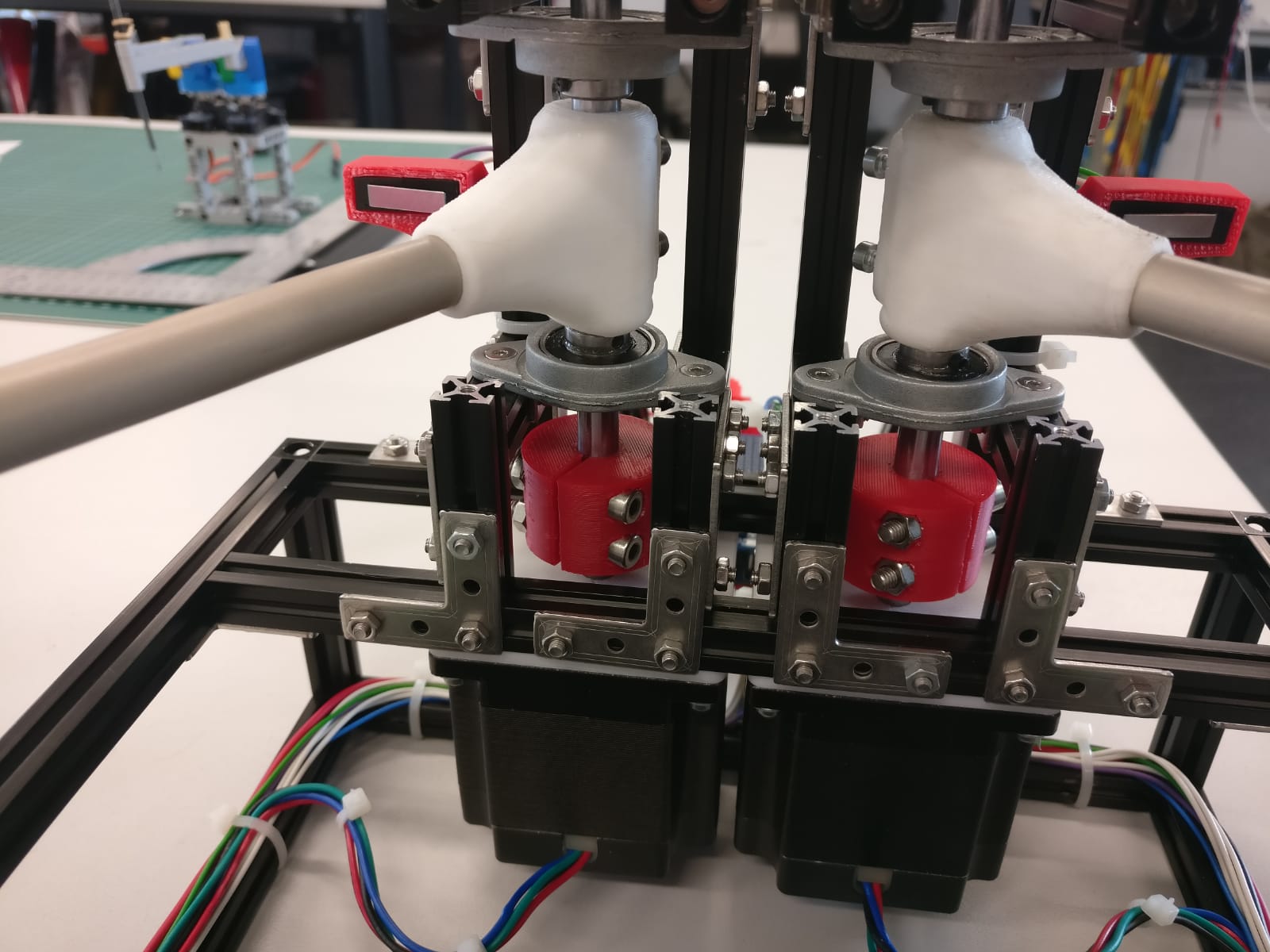
}See here the finished first prototype. It´s also wired and ready to start.

My college Peter wrote the first program to make the two motors move so let´s take a look at the firt try:
As you sethe pencil is swinging around so we had to upgrade the software and hardware. So first we tried out some different settings for the motor settings with more ore less power and with different resolutions. That makes the results just a few steps better. So we tested the delay between two step signals and measured a frequency of 19Hz. That is quite slow so we optimized the software to make the calculating workload less. That makes the results a lot more precise.

See here the difference between the first try and the second one after some setting changes and software optimizations.
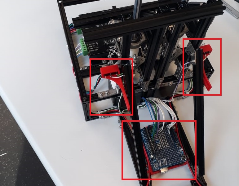
The circle we wanted to draw wasn´t realy round so we had to install a homing routine. Therefore I printed the end stop holdings the last week.

The circle we wanted to draw wasn´t realy round so we had to install a homing routine. Therefore I printed the end stop holdings the last week. Together we implemented the routine. See the process in the video below.
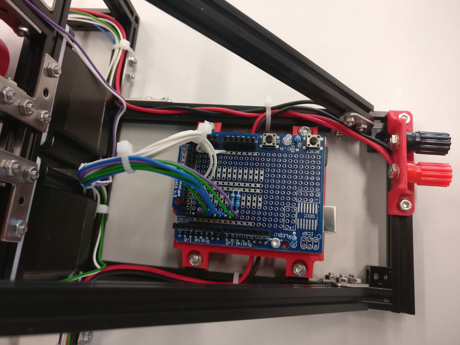
After the homing process our circle looks pretty good so in the next step peter implemented the direct control of the robot via touchpad.
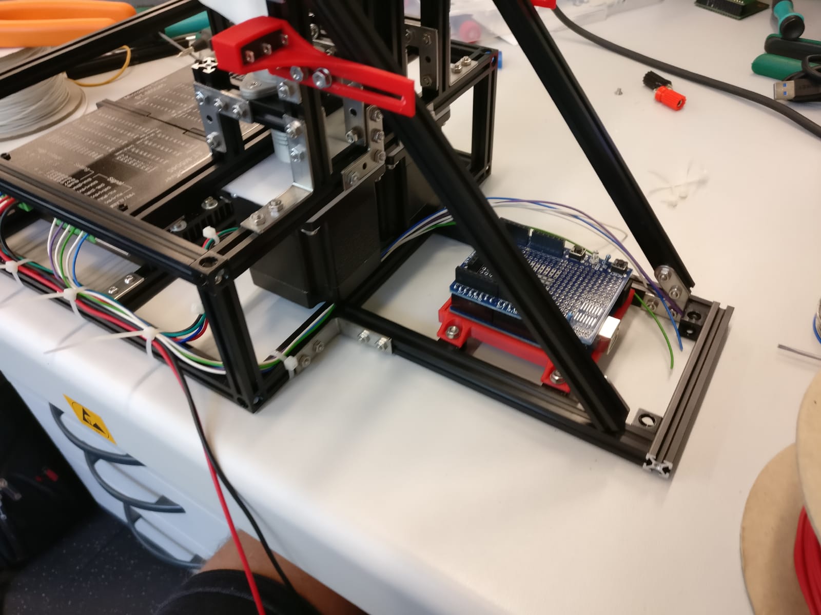
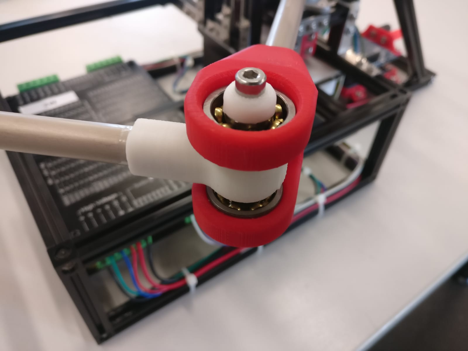
See here the finished machine with the changed clutches.

The Software
The Software is really bad and not optimized for the given problem.
It just was not enough time to make it good.
The big problem at this Software conclusion is that it was write for Servos and not for Steppers.
We have taken the old Software that Peter wrote in the Interface and Application week and used this with new Arduino code on the Machine side.
Peter´s old Software calculates the angles of the Motors to a given coordinate and streams the tow angles continuously out.
The software don't wait of the Machine to reach the given angle.
With the Servos it was no big deal because the Servos run asynchronous to the controller.
To set the Stepper in position the controller must do that actively and can not receive serial data at the same time.
So you must synchronize the machine and the software.
You can change the time in the host Software for the streaming interval or you can speed up the steppers so they can faster reach the given angel.
But when the timing are bad the machine jerks.
And this is not good.
The Problem can be solve when the machine tells the host Software wehn finish a command.
The Code for the host programm can be found here: Week 12
The Arduino Code:
#define M1_DIR 4
#define M1_PUL 5
#define M1_ENA 3
#define M1_LIM 9

#define M2_DIR 7
#define M2_PUL 8
#define M2_ENA 6
#define M2_LIM 10

#define ON_PULSE 1
#define OFF_PULSE 5
#define OFF_PULSE_HOMING 600

#define STEPP_REV 50000

float one_deg = (STEPP_REV / 2) / 180.00;

int incomingByte[10];

void setup() {
  Serial.begin(115200);

  pinMode(M1_DIR, OUTPUT);
  pinMode(M1_PUL, OUTPUT);
  pinMode(M1_ENA, OUTPUT);

  pinMode(M2_DIR, OUTPUT);
  pinMode(M2_PUL, OUTPUT);
  pinMode(M2_ENA, OUTPUT);

  pinMode(M1_LIM, INPUT);
  pinMode(M2_LIM, INPUT);

  pinMode(11, OUTPUT);

}
int M1_stepp = 0;
int M2_stepp = 0;

long i,x,M1,M2,iii,dec,M1_stepp_diff,M2_stepp_diff;
bool first_last;
float M1_F,M2_F;


void loop(){

        if (Serial.available() > 0) {
            incomingByte[i] = Serial.read();
            if(incomingByte[i] != 36){
            if(incomingByte[i] == 0x26 || incomingByte[i] == 0x21){
              if(incomingByte[i] == 0x26)first_last = true, M1 = 0;
              if(incomingByte[i] == 0x21)first_last = false, M2 = 0;

               iii = i-1;
               dec = 1;
               for(int ii = 0;ii<i;ii++){
                  dec = 1;
                  for(int p = 0;p<iii;p++){
                    dec = dec * 10;
                  }
                  if(first_last == true)M1 = M1 + (incomingByte[ii]-48)* dec;
                  if(first_last == false)M2 = M2 + (incomingByte[ii]-48)* dec;
                  iii--;
               }

               M1_F = (float)M2 / 1000.00;
               M2_F = (float)M1 / 1000.00;

              if(x >= 1){

                float M1_stepp_diff_F = (M1_F * one_deg) - (float)M1_stepp;
                M1_stepp_diff = M1_stepp_diff_F;

                float M2_stepp_diff_F = (M2_F * one_deg) - (float)M2_stepp;
                M2_stepp_diff = M2_stepp_diff_F;

                Serial.print(M1_stepp_diff);
                Serial.print(" - ");
                Serial.println(M2_stepp_diff);

                x = -1;
                digitalWrite(11,HIGH);
                moveStepper(M1_stepp_diff,M2_stepp_diff);
                digitalWrite(11,LOW);
               }
               x++;

              i = 0;
            }else{
              i++;
            }

          }else{
            Serial.println("Homing");
            homing();
          }

       }
}

int moveStepper(int M1_diff, int M2_diff){

  boolean DIR_M1 = true;
  boolean DIR_M2 = true;

  if(M1_diff < 0)DIR_M1 = false , M1_diff = M1_diff * (-1);
  if(M2_diff < 0)DIR_M2 = false , M2_diff = M2_diff * (-1);

  digitalWrite(M1_DIR,DIR_M1);
  digitalWrite(M2_DIR,DIR_M2);

  int biggest_diff;

  if(M1_diff >= M2_diff)biggest_diff = M1_diff;
  if(M2_diff >= M1_diff)biggest_diff = M2_diff;

  boolean dubbelSpeed = true;
  boolean M1_Move = true;
  boolean M2_Move = true;

  for(int i = 0;i < biggest_diff;i++){

    if(M1_diff >= i){
      makeStepp(1,dubbelSpeed,false);
      if(DIR_M1 == true)M1_stepp++;
      if(DIR_M1 == false)M1_stepp--;
    }else{
      M1_Move = false;
    }

    if(M2_diff >= i){
      makeStepp(2,dubbelSpeed,false);
      if(DIR_M2 == true)M2_stepp++;
      if(DIR_M2 == false)M2_stepp--;
    }else{
      M2_Move = false;
    }

    if(M1_Move == false || M2_Move == false)dubbelSpeed = false;

  }

}

int makeStepp(int Motor, boolean dubbelSpeed, boolean homing){

  int Stepp_OFF_PULSE = OFF_PULSE;
  if(dubbelSpeed)Stepp_OFF_PULSE = Stepp_OFF_PULSE / 2;
  if(homing)Stepp_OFF_PULSE =  OFF_PULSE_HOMING;

  if(Motor == 1)digitalWrite(M1_PUL,HIGH);
  if(Motor == 2)digitalWrite(M2_PUL,HIGH);
    delayMicroseconds(ON_PULSE);
  if(Motor == 1)digitalWrite(M1_PUL,LOW);
  if(Motor == 2)digitalWrite(M2_PUL,LOW);
    delayMicroseconds(Stepp_OFF_PULSE);
}


void homing(){

  boolean HomingMotor = true;
int i;
while(i < 2){
  if(HomingMotor){

    digitalWrite(M1_DIR,HIGH);
    digitalWrite(M2_ENA,HIGH);

    while(1){
      makeStepp(1,false,true);
      if(digitalRead(M1_LIM))break;
    }

    delay(200);
    digitalWrite(M1_DIR,LOW);

    while(1){
      makeStepp(1,false,true);
      if(digitalRead(M1_LIM) == false)break;
    }

      delay(200);

    for(int i = 0; i <= STEPP_REV / 4;i++){
      makeStepp(1,false,true);
    }

      M1_stepp = STEPP_REV / 4;

      delay(1000);
      digitalWrite(M2_ENA,LOW);
      delay(1000);
      HomingMotor = false;

  }else{

    digitalWrite(M2_DIR,LOW);

    while(1){
      makeStepp(2,false,true);
      if(digitalRead(M2_LIM))break;
    }

    delay(200);
    digitalWrite(M2_DIR,HIGH);

    while(1){
      makeStepp(2,false,true);
      if(digitalRead(M2_LIM) == false)break;
    }

    M2_stepp = 0;
    delay(200);
    moveStepper((STEPP_REV / 8),(STEPP_REV / 8));

  }
  i++;
}

}
Downloads
| 3D parts files for the frame | Download |
| Nema23 datasheet | Download |
| SVG and GCodes files(zip) | Download |
| 3D parts of the Arm(zip) | Download |
| Software for the Machine(zip) | Download |