Electronics Design
Task:
- Use the test equipment in your lab to observe the operation of a microcontroller circuit board
Jimena's, Tanja's, Peter's and Lukas's Part:
UART transfer
UART stands for Universal Asynchronous Receiver/Transmitter.
It is commonly referred as serial port.
UART is a peripheral for point-to-point communication between two devices.
Communication occurs in SERIAL,which means one bit at a time.
UART has two communication PINs: RX and TX.
UART is asynchron, that means that no CLOCK line is needed.
Both devices are synchronized by time.
The devices show fix baud rates - it's the transaction speed measured in bit per second.
At the beginning of the transmission, the data line is set to logical '0'.
At the end of the transmission the data line will be set to logical '1'.
The data is transmitted in a normal byte block.
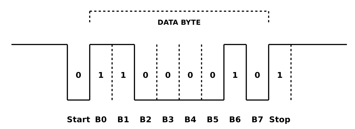
Transmission of a char “C” hexcode 43, binary 0100 0011
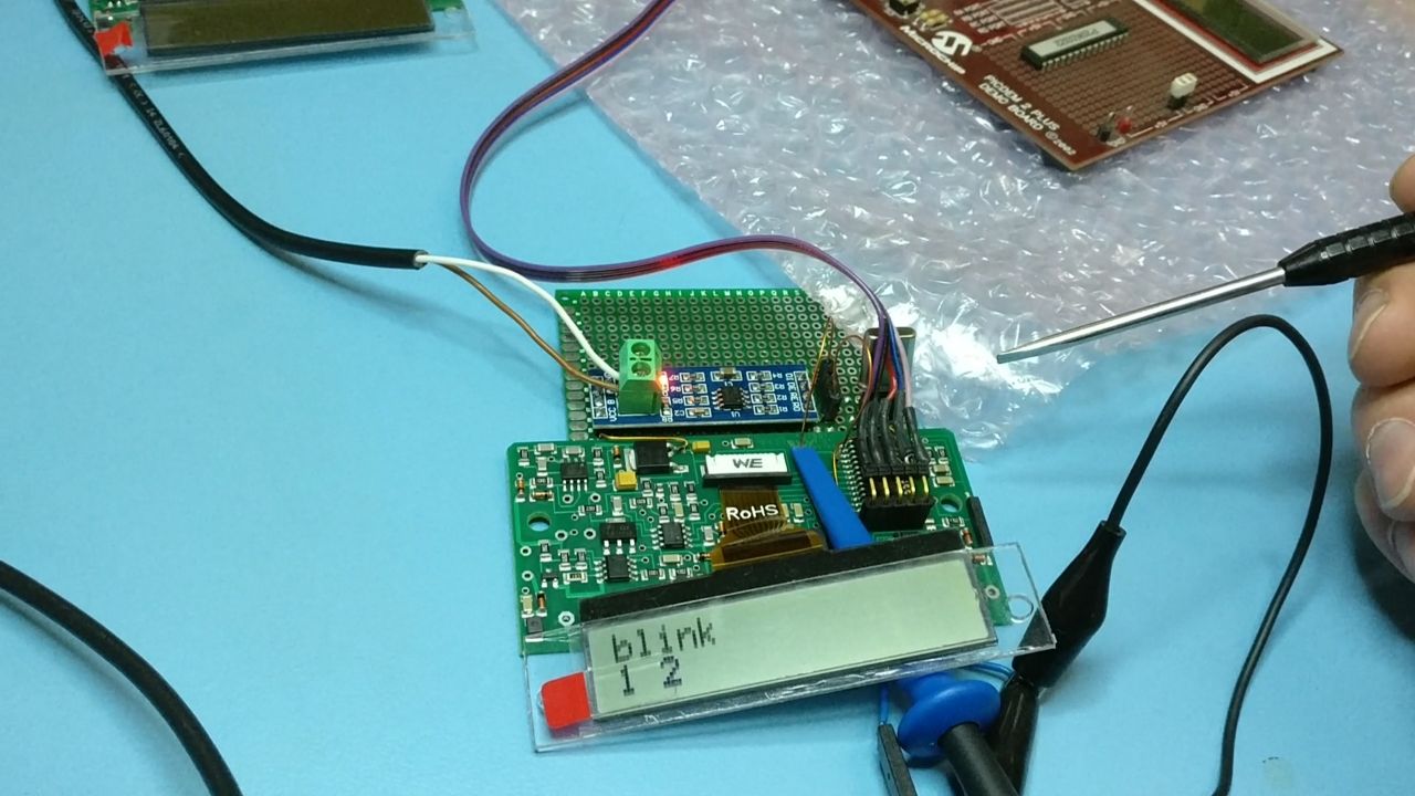
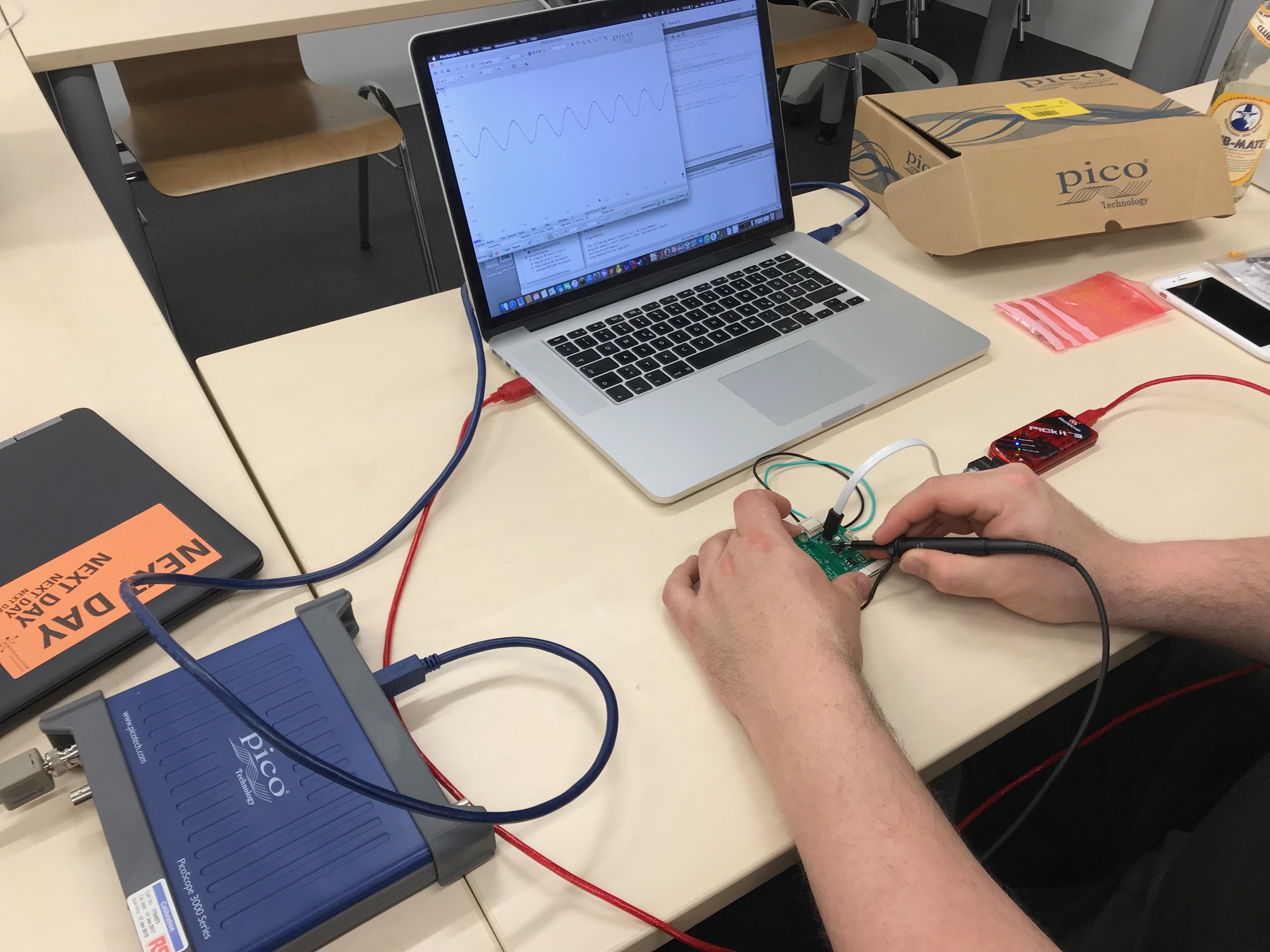
Pic controller with two connected oziloscope probes.
I have defined a trigger pin that I set to HIGH when the transfer starts and goes LOW when it ends.
I connected a probe of the Oziluscope to this pin and put the trigger on it.
I connected the other probe to the UART TX pin.
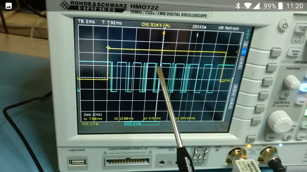
Yellow is the trigger pin, blue is the TX line.
Using the multimeter to check the PCB
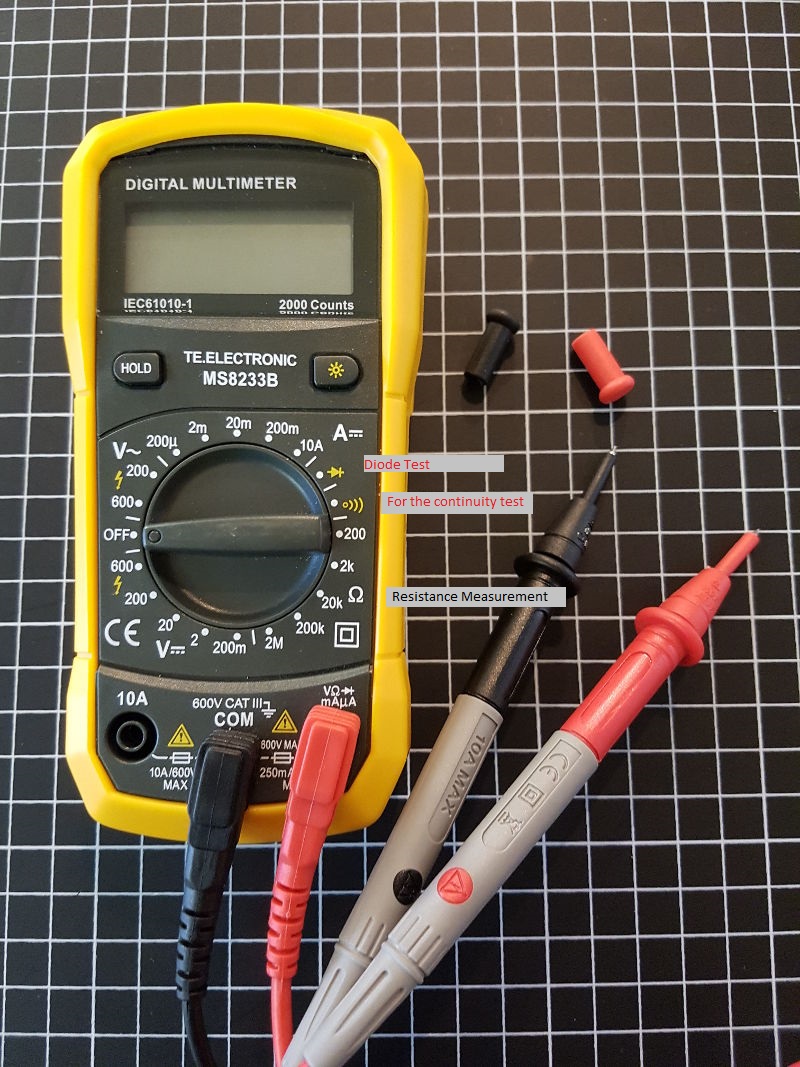
Continuity Test:
check the continuity of the electrical path ways with a multimeter. Turn the multimeter to the desired test function and check if it is in working condition by touching the both probes (test leads) together. Most multimeter will beep or show “0” or a low value on the display. Place the probes on the connection points and should hear a beep. If there is no connection, the display will show OL.
It is also important to check each component, if it’s not damaged. For example the resistors with the:
Resistance Measurement:
Remember to ensure the circuit under test is not powered on. The current resulting could damage the multimeter.
Chose the resistance measurement range: 200 Ω, 2 kΩ, 20 kΩ, 200 kΩ, 2 MΩ. Perhaps your multimeter has another ranges.
Connect the black probe to COM and the red one to Ω. Take the resistor you want to measure and read the resistance with the test leads.
Measurements higher than 1 MΩ can take a couple of seconds.
Read also the manual of your multimeter for more information.
Daniel's and Christoph's Part:
Watching an oscillator
Any microcontroller will need some kind of clock source. And while some can use an internal oscillator to various degrees (mostly limited by accuracy), Christoph's motor board uses a ceramic resonator to get a reasonably accurate (but small and cheap) 8MHz clock base.
A crystal (or resonator) based oscillator is a relatively simple thing - it's mostly an amplifier, built to be really, really unstable. With the output just fed back into the input, it would oscillate at a (rather high) frequency limited by its components, temperature, voltage and some other factors, so it wouldn't be accurate in any way. At that point, the resonator (or crystal) comes in - It acts as a very sharp filter, so it only lets through the frequency you want to have. Which, in turn, gets amplified by the amplifier, leading to a stable oscillation at a well defined frequency.
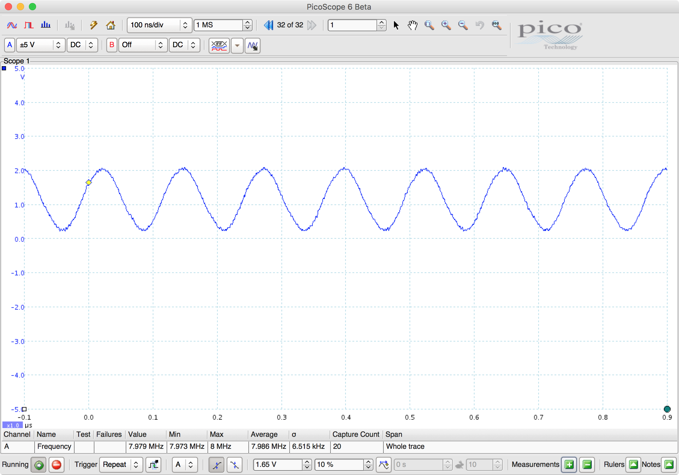
In practice, this can be, of course, more or less measured. At the input of the resonator, the very unstable amplifier will try to put on a (more or less) square wave, switching hard between 0 and its 3.3V supply voltage:
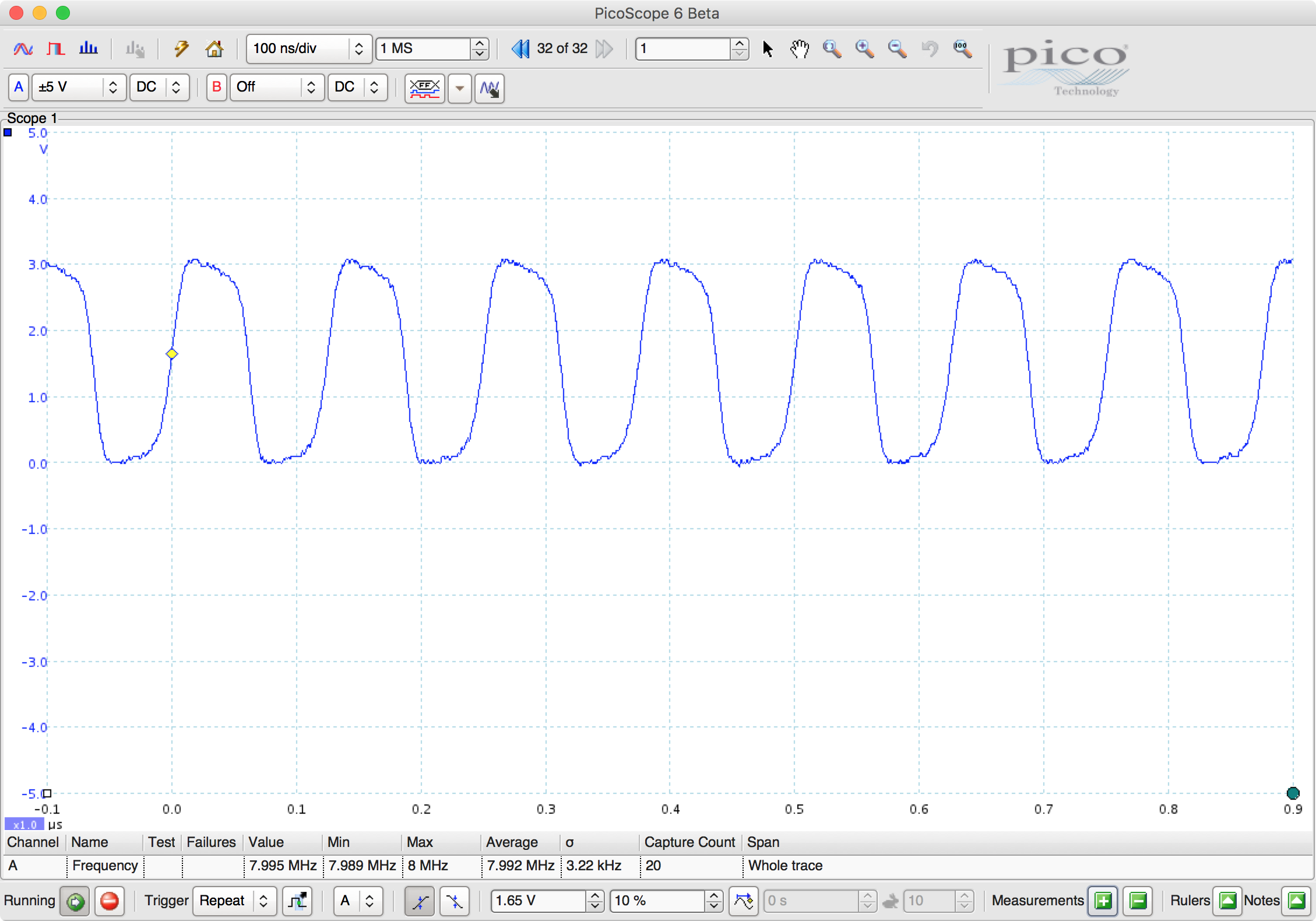
The resonator will filter out a signal of more or less one single frequency - in this case, 8MHz. It's not purrfect, of course, so the output signal is neither of the same amplitude nor a perfect sine wave. It's a lot closer to a sine wave, though: