final project -- weekly assignments -- about me -- fab academy
Oh my god LAZORS!!!
Week 02: 2D CNC cutting
This week's assignment was to get to work with our laser cutter and make a parametric press-fit construction kit. Not a very specific assignment, and last year's stuff looks about as diverse as one can imagine with that. So, a few more precise ideas:
- Low number of different parts for maximum fun (think of the classic Lego brick that was good for any idea imaginable, not what they're doing today!)
- I want to build a dome and other "large" structures, so the small, square parts of Neil's system won't do
- It should be as parametric as possible so it can be adapted to the material available (building a proof-of-concept model from cardboard, or a lamp from plastic or even sheet metal...)
Phase 0: Ideas
My first idea for a building kit was to make beams (from two or three parts, in a T or I configuration) in a set of different lengths (like 1, 1,41, 2, 2,82, ... length units) and a set of connectors. After a lot of time thinking about those (I was away from the lab anyways) That idea was, without ceremony, ditched. Doing 3D connectors in 2D just doesn't work out if you don't want to stay in strict orthogonal space, and that would have been boring.
So, searching for inspiration in last year's archive, I stumbled upon Iain Chalmers' page and his construction kit. It looks really cool, and it seems to be good for almost anything, so it's a good start. Those 90° are still boring, but that's easy to change. Also, just making a dumb copy of his design would be an absolute no-go. So, looking back at my ideas, a parametric approach could be fun: If I can do a parametric approach to material thickness, why not do the same to the angles involved? A construction kit could be done for 60° (triangle), 90° (boring tetragon), 108° (pentagon) and so on. It can't be that hard with a computer, can it?
Phase 1: Geometry
It can't be that hard, so let's first make a sketch of it:
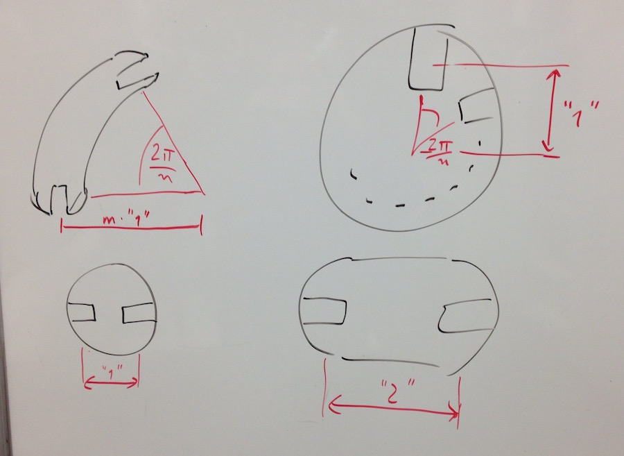
A few thoughts about the geometry of a system are already in that sketch. To be able to build closed figures, angles and lengths have to match up. So how do we get the length of a piece?
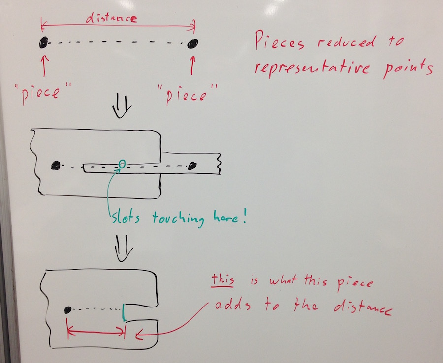
For straight pieces, each piece should add 1/2 (or 1 1/2, 2 1/2, ...) of the system's standard spacing to make them fully interchangeable. A system with 45° angles allows for a diagonal connection, needing a second length of 1.41 times the system standard. Evil stuff.
The curved pieces can be fun and look great, and they allow for a cool way to build 3D things. To build a system allowing closed figures, they have to match in some way, though. That is easy, angle-wise, by just having them at the system angle or a multiple of it. Using multiples of the system length as a radius should make them fit in nicely, too. They'll just need some special work at the ends so they don't end up being a combination of two straights and a curve...
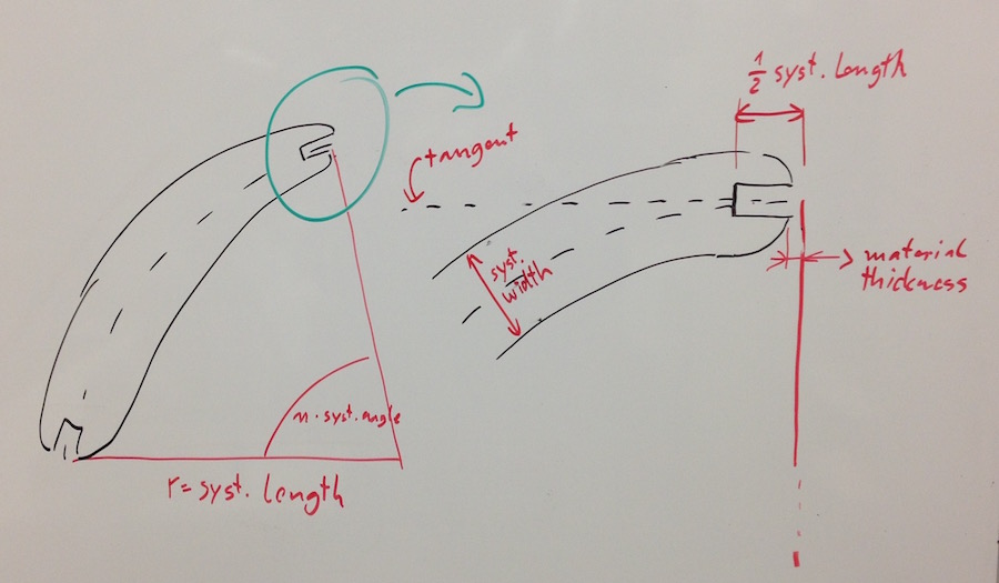
Last to be defined is the outline of the pieces. Just by general principle, I want that to depend on the system length so I can scale the whole system. Adding a parameter for a standard width of the longer parts would be cool, too. Also, I want the pieces to be as round as possible, so any corners will be rounded down to nothing. Last, the slot depth must be limited, too, to get multiple pieces into a crowded connector.
So, we end up with four system parameters: System length, system width, system angle and material thickness. Also, for the straight and curved pieces, a multiplier is possible to make them longer or to cover a wider angle.
Phase 2: Drawing with math
My first idea had been to do the actual CAD work in Antimony, as that would have been a cool way to get such a mathematical, parametric set of models done. I'm missing a few features to do that comfortably though: I can't, at this point, have a parameter work across multiple files with multiple models. Also, comfortably using pieces of a model (like a slot desing) across multiple designs isn't implemented yet, so experimenting with slot designs would end up being a pain. Last, outputting a mathematical model to a rendered pixel file as the only output option, then converting it back to a vector format to plot it is a strange and lossy way to handle geometry.
I did, in the end, end up with OpenSCAD, even though I don't really like it. It works (no doubt about that), but the syntax is just horrible and some quirks were just introduced to drive you mad. It's still a horrible mess of source code, but it works. It took some time to figure out the buildup of the geometry, and the definition of the slots has proven to be rather stupid (their reference now is their opening, which doesn't work out with the curved pieces). There is a lot of room for improvement here.
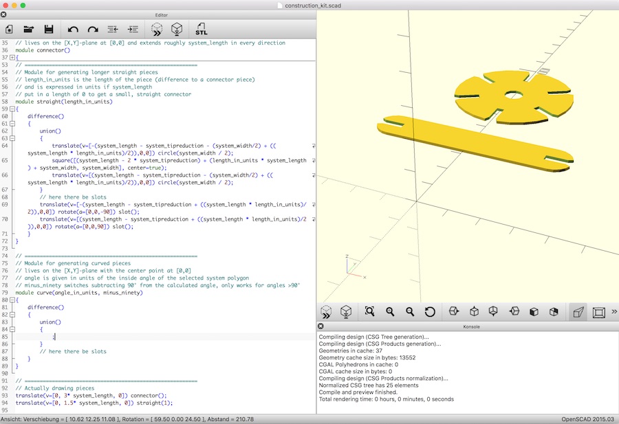
You can download the OpenSCAD-file, of course, and play with it. Beware of the curved parts, their geometry is flawed as of now.
Phase 3: Cutting
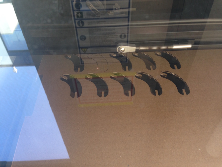
To actually cut the pieces on our laser cutter, first we had to find out how wide to cut the slots. The laser cuts out a slot of a small, but very real width, so for a press-fit the material thickness has to be corrected by that to get the slot size. Daniel and me did that with a pair of combs with "growing" slot sizes. It just worked, there wasn't really anything difficult about it.
Also, getting the parts cut means finding out the settings for cutting cardboard on the laser. Cardboard is easily upset and reacts to being upset by bursting into flames. Keep a bucket of water nearby when doing this at home - absolutely not to pour it into the cutter, but to throw flaming pieces of cardboard into it. Also, start at really low setting, we ended up way lower than we had anticipated having only cut wood in the past. We ended up using 20% power at 2500Hz, with 100% speed, but those values can never be more than a starting point given that they are highly material dependent.
Cutting the actual construction kit parts works fine by exporting them to an svg file and importing them into VisiCut. VisiCut doesn't sort the lines into a sensible order, you either have to do that by hand (putting different groups of lines into different groups and different jobs), or you have to live with parts first being cut out and then structured internally. As we don't have the original, very thin supporting grid Epilog offers for our laser cutter, we ended up with some charred parts. That will have to change, in some way, in the future.
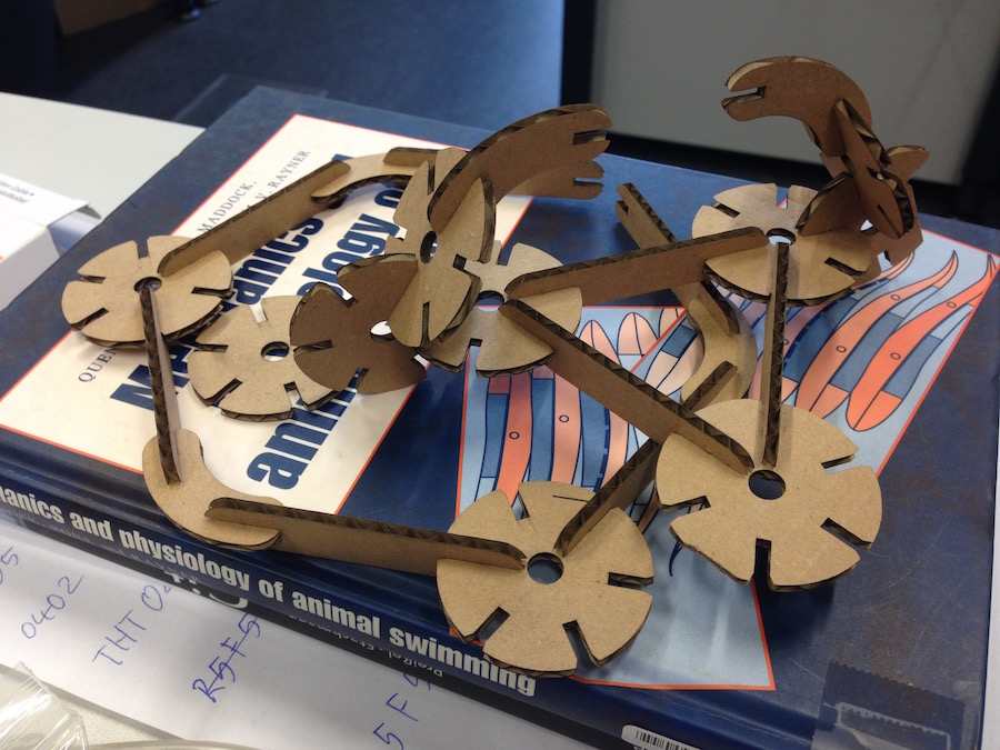
There will be more trial and error with those parts, and improvements to the geometry... They're fun!
Additional assignment: Vinyl cutting
This week's assignment also got us active enough to finally push some life into our cheap-ass vinyl cutter. I did this together with Daniel, too. In the end, we got the cutter to cut by generating cutting paths with a modified version of InkCut that can generate the DMPL output the cutter needs. That is a plotting language similar to HPGL, most of the difference is that it went extinct long ago and isn't used by anyone any more - except the people behind our cutter. It works, though, and it cuts really fine and precise.
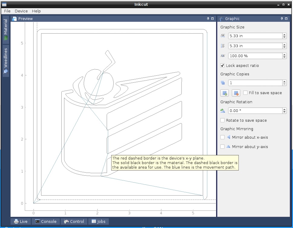
The test image I used here is the portal-cake I found here via google image search, though I suspect that it's actually taken from the game files. I originally just used the fabmodules to vectorize it (by generating a toolpath at zero offset from the edge of the black areas) and fed the resulting svg into inkcut, with the result as visible in the image above, on the left. The outline of the symbol touches the side of the image - At two of four sides. That, of course, generates no toolpath in that area, so I had to change something. I cut cut off the rim in gimp as I didn't want it, then vectorized it again - First at a larger scale to test with the pen, then at the smaller scale again to cut from vinyl.

Inkcut is a plugin for Inkscape, so it's a pain to work with, but it does the job:
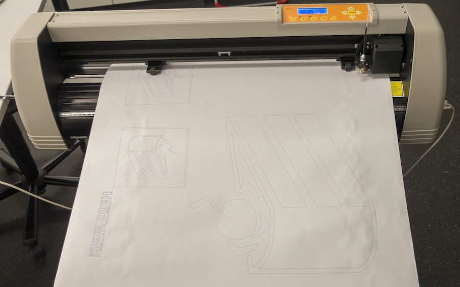
Since inkcut couldn't connect to the plotter for some reason we did not investigate, we had to plot to a file, then send that file to the plotter:
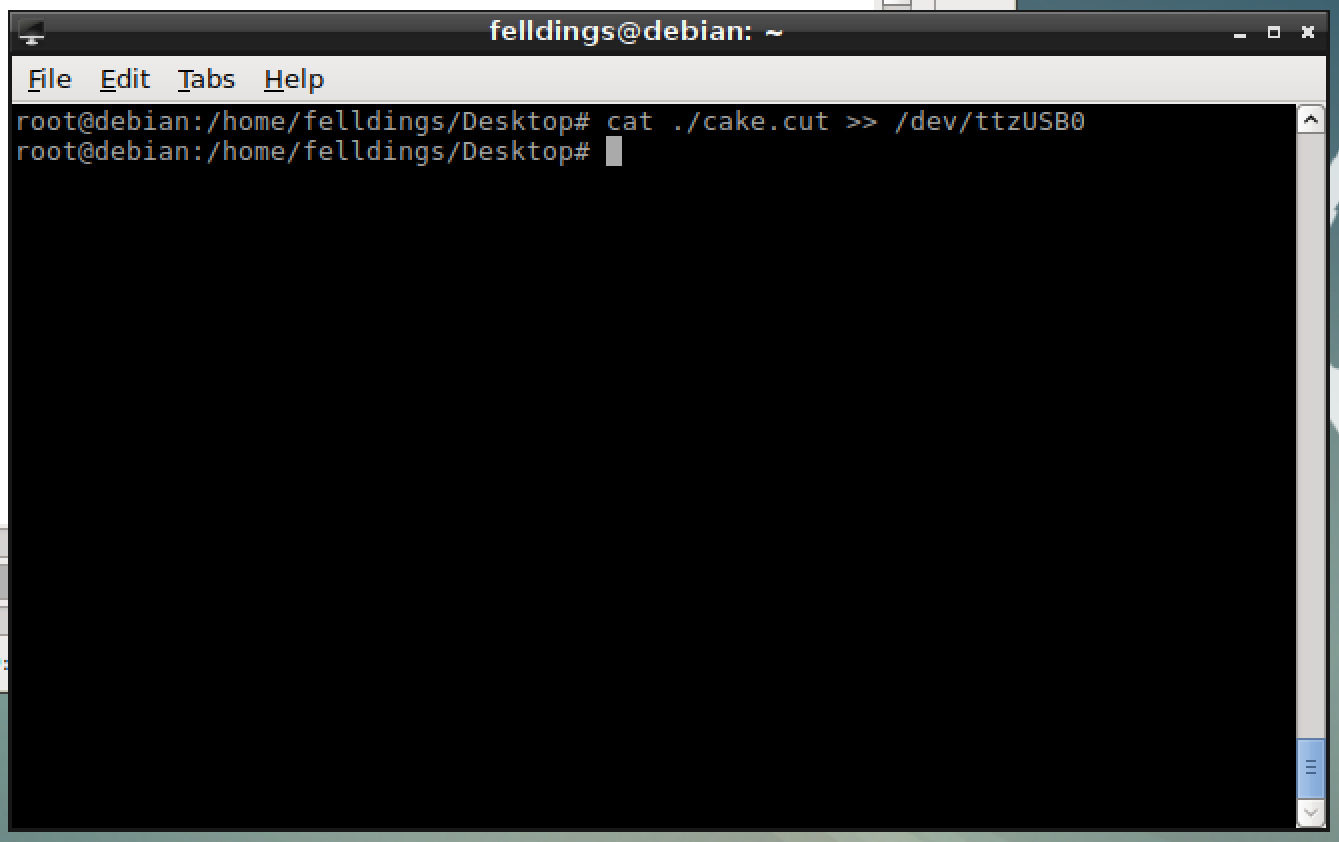
We'll do some more experimenting with the cutter to get the cut settings right (we just used the standard settings InkCut provides, which left us with a few not completely cut out figures) and maybe use one of the electronics / programming assignments to build a USB adapter that translates camm (or any other common language) to DMPL on the way so we can use more common tools.
2018 Update No. 1: That sticker still exists and still sticks to my notebook:

2018 Update No. 2: When there was time to look into the plotter again, it had already been stowed away for quite some time, and replaced for everyday use by a bunch of cameo plotters. I won't invest time into it in that case, and consider that interesting journey to be over.
2018 Update No. 3: The dmpl-modified version of Inkcut never really was maintained in any way, so of course it was not updated when Inkscape changed its extensions system. It will not work with a somewhat current version of Inkscape, so the bits and pieces about it should be considered to only be of historical value.
final project -- weekly assignments -- about me -- fab academy
