final project -- weekly assignments -- about me -- fab academy
Week 14: 90 Ohms of Fun
CAN bus has been used for industrial machines and cars for quite some time now, and I wanted to have a shot at it for quite some time, too. So, since I'm using fabacademy to do stuff I didn't find the time to do before, and since I had to redo the servo drives anyway, I got at it.
The Physical Side of Things
The physical side of CAN is actually quite simple. It uses a two-wire bus, with one of the wires called "high", the other called "low". To signal a 0 (called "dominant"), the levels of those two wires are pulled apart - "high" up to roughly 5V, "low" to ground. To signal a 1 (called "recessive"), or to not signal anything, the wires are both released, and are pulled together passively by the termination resistors.
This allows for smoke-free collisions - Signalling differently at the same time will damage none of the signalling nodes, and the result will always be a clean "dominant" 0 (which is why it's called dominant). This is used, in the protocol, to deal with collisions, and (in most cases) to even continue sending of the highest priority message involved.
To make the whole bus somewhat resistant to electrical disturbances, the levels of the two lines are interpreted differentially - As in, only the difference in voltage between them is measured, not their absolute voltages. The theory behind that is that any kind of noise will, under the assumption of both cables being physically almost in the same place, affect both of them almost equally, cancelling out in the differential view. This theory works for sensibly done cabling, and is used by a lot of bus systems (like Rs-485 as used with the MTM-nodes, or most versions of Ethernet). Implementation has its limits, of course, so you still need a ground wire and have to keep all nodes at roughly the same absolute level (or use isolated transceivers, which is expensive).
I will not dive into building a CAN transceiver during this assignments, and I do not plan on ever doing it, as it's quite a complicated affair to adhere to all pitfalls the standard offers. Single-chip transceivers are available in great numbers and cost next to nothing, so I will just use one of those. The one I chose, a TI TCAN330, was the smallest one available that works at the 3.3V I have on the boards. There are smaller ones, but getting an additional 5V rail onto the boards more than counters that and is a lot more expensive.
The cables for CAN bus are supposed to have an impedance of 120Ω, which is quite a normal thing for a twisted pair of normal, thin wire. I don't have any 120Ω cable, though. What I could quickly acquire was a large spool of cheap USB cable that Reichelt had available. It has the advantage of having two slightly thicker wires for power (They should work for the placer or any other small machine, given that they will be used for up to 2A when charging USB devices), but it is specified to have an impedance of 90Ω. Which is not bad - at least it's specified at all. So, my termination resistors will be at 90Ω to match that, and the transceivers will have to live with the lightly higher load.
As a side note, a colleague actually measured the impedance for me. It came out at 91Ω, so the specification is way more precise than I would have thought.
The Logical Side of Things
Unlike simple specifications like Rs-485, CAN does not only specify the physical side of how to transfer a bit, it also specifies a message format and a safety mechanism against disturbances on the bus, as well as a way to schedule bus access, roughly the same way Ethernet does. I don't really like the OSI layer model, but to keep with it, CAN specifies up to level 3 (while Rs-485 only specifies level 1).
The specification has grown over time, and is quite complex with a lot of edge cases and ways to do stuff. I'm using the most basic version here, with "short" addresses and no special packet properties. This gives me a packet like the one below:

(Image by Wikipedia user "Endres", CC-BY-SA-3.0)
The interesting parts (for me, right now) start at the Arbitration Field (marked in green). This bit field is an 11 bit Message-ID, which at the same time defines the priority of the message: The lower the ID, the higher the priority if a collision occurs during sending this bit field. This can be thought of as a target address for the message, in the way of thinking CAN employs it only defines the type of message, though: CAN doesn't care who needs data, CAN cares about throwing data you have on the bus. So, the message ID tells you what kind of data it is, and you can read it if you're interested.
The next interesting part is the RTR bit (marked in blue). As CAN doesn't really care about who needs data, there must be some way of requesting data if it doesn't appear by itself on the bus. To do that, you send an empty message, that is, one with no data in it, with the message ID of the data you want to have, and the RTR bit set.
The amount of data in a message is flexible and can be from 0 (no data) to 8 Bytes. To tell the receiver about the length of the data field, there are four bits of Data Length Code (marked in yellow). Theoretically, this could encode up to 15, but that doesn't change that the standard limits the amount of data to 8 bytes.
Next, we have the Data Field (marked in red). If we have it. It's data, whatever you put in there. In the example, it's one byte.
Following the data, a CRC checksum is transmitted. This is to make sure that a message is either received correctly down to the last bit, or altogether rejected by a receiving node, even when there are bad disturbances on the bus. It's a bit of mathematical magic, and it can be implemented very efficiently in hardware.
Layers upon Layers...
To use the bus for my needs, I need to add another layer of definition to it: My own message definitions. I could theoretically use one of the existing ones, like CANOpen (which is anything but open and quite expensive to just read) or CANAerospace, but I don't have time or resources to understand those right now. My own, simple definition will have to do for now:
- ID 0x0001 is an emergency stop message and contains only one data byte, the content of which is ignored by now. Any node receiving an emergency stop packet will stop any motors it has.
- ID 0x0002 will be used for clock synchronisation of the nodes at some point. I haven't implemented anything of that yet and do not plan to do it during fabacademy, as I'm seriously running out of time, but parts of it are already in the CAN code. For now, those messages are ignored.
- IDs 0x001* is an axis speed command. It has the full eight bytes of data, with the commanded speed for four axis as signed 16 bit values. With four bits to identify 16 groups of 4 axis, there is more than enough space for those, and the placer will probably only use IDs 0x0010 and 0x0011.
- IDs 0x002* (and probably others in the future) allows for configuration data to be sent to the axis. Details of this are not there yet as I haven't implemented it yet. Parts of it are already in the CAN code, though. For now, those messages are ignored.
Making it Run
the dsPIC on the motorboard comes with a CAN peripheral, which does all the grunt work for us - Give it the contents of a message and it will silently build in all the protocol needed, wait for the bus to be free, and send it. Or even resend it if it drew the short one in a collision. It will also read messages from the bus, check their integrity and even filter them so you only get the ones you're interested in.
Microchip offers a reasonably well written datasheet on the details of the specific version of their CAN module that comes in this PIC, DS70645. It's a bit hard to get an overview of what you actually need to do, as the module is complex enough that it has too many registers to be accessed at the same time, and it only works when used together with the DMA module.
Microchip also offers example code, CE427, which will not work on my hardware, and doesn't seem to work correctly on this family anyway.
There is also the Microchip Code Configurator, part of their MPLAB X IDE. It can produce a project with all the code for initialising the hardware already in, with a nice and usable graphic interface:
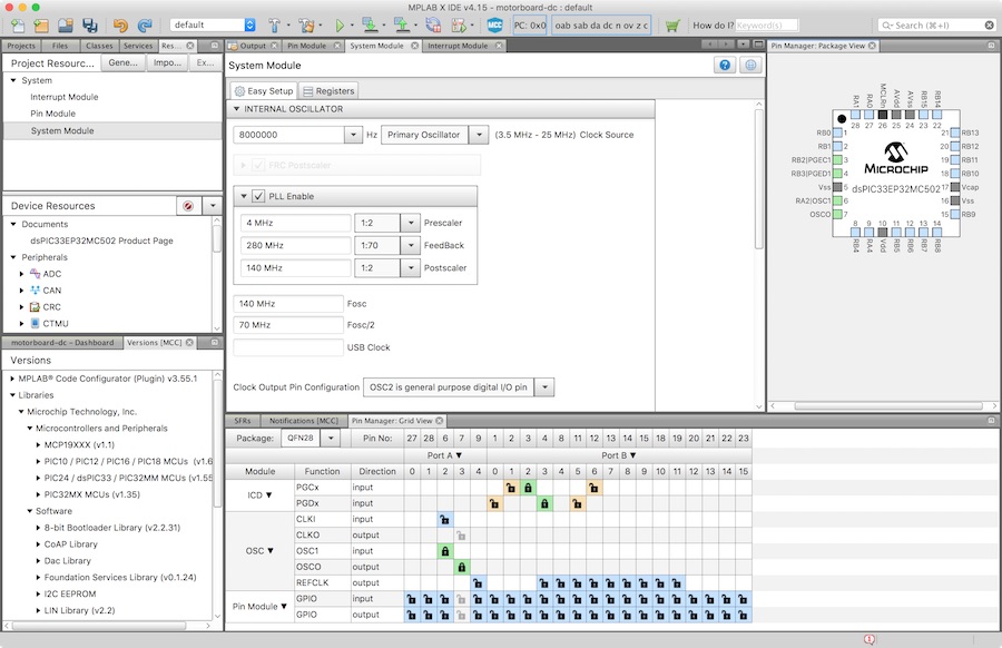
When I started out on the sources for this project, it didn't support my specific family of a dsPIC yet, so I couldn't use it. I tried for the CAN module, and the results were reasonably usable, but since it would have been really hard to combine those with the code I already had, I ended up not using it.
What I used, in the end, is mostly the example code from the datasheet - Examples 21-1 and 21-4 contain most of what I need. I had to make adaptations, of course - The examples run at a different clock speed, they use a different baud rate, and they filter for only one kind of message. Also, the examples constantly poll for new messages, which is somewhat asinine. I found a good example on how to tackle interrupt based reception in the CE427 code example, and it works fine.
Most of the work to get the CAN module running is, due to the complexity, the initialisation. To do this, the first step is to command the module to switch to its configuration mode, which can take some time:
// This cannot be set directly, but must be requested and waited for.
C1CTRL1bits.REQOP = 4;
while(C1CTRL1bits.OPMODE != 4);
Now, the configuration can be set, beginning with the bitrate settings. CAN uses a rather complex way of defining a bit through different phases, so just setting the bitrate is a complex thing. Section 21.9 of the datasheet is some help, as is Application Note AN754 and a number of web pages:
// To get from 70MHz (F_CAN, half of the peripheral clock) to 500kHz we need
// an overall divider of 140. A CAN bit is divided into 8-25 TQ, and the
// prescaler is configurable from 1 to 64.
// One nice and clean division is a CAN bit of 20 TQ and a prescaler of 7
// Another possibility is 14 TQ and a prescaler of 10, but I won't do that
C1CFG1bits.BRP = 6; // set prescaler to 7
C1CFG1bits.SJW = 1; // set sync phase to 2 TQ (standard says 1, should be more robust with 2?)
C1CFG2bits.PRSEG = 5; // set propagation phase to 6 TQ
C1CFG2bits.SEG1PH = 5; // set phase 1 to 6 TQ
C1CFG2bits.SEG2PHTS = 1; // phase 2 can be freely programmed
C1CFG2bits.SEG2PH = 5; // set phase 2 to 6 TQ
C1CFG2bits.SAM = 0; // bus is sampled once at the sample point
The CAN module needs a number of message buffers in normal RAM, which have to be defined elsewhere. It has to be told, of course, how many there are, and which ones should be used for its FIFO functionality (which I don't want to have):
C1FCTRLbits.DMABS = 2; // there are 8 buffers
C1FCTRLbits.FSA = 7; // not using the FIFO, so it points to the last buffer that exists
The amount of configuration registers the CAN module has is so large that microchip mapped some of them onto the same addresses, with a switching mechanism to access them. So, to configure the message filters for receiving messages, we first have to switch to that register group:
Now, we can set filters. I'm using four filters, each of which represent one message ID. To be able to have broader matches, those filters can also be masked, so specific bits are ignored during filtering. Any message passing a filter is then sent to a message buffer for reading, so you also have to configure the filters to use a specific buffer.
// be received!
C1FEN1 = 0; // Someone is very stupid, so by default all filters are active
// and we have to first disable all of them...
// Filter 0 for clock syncing messages (ID 0x0001) and emergency stop
// messages (ID 0x0001) -> buffer 4
C1FMSKSEL1bits.F0MSK = 0; // Filter 0 will use mask 0
C1RXM0SIDbits.SID = 0x07FF; // All filter bits are active
C1RXF0SIDbits.SID = 0x0001; // Filter filters for SID 0x0001
C1RXM0SIDbits.MIDE = 1; // Use this filter on standard identifiers
C1RXF0SIDbits.EXIDE = 0; // Do not use this filter on extended identifiers
C1BUFPNT1bits.F0BP = 4; // Messages fitting filter 0 go into buffer 4
C1FEN1bits.FLTEN0 = 1; // Filter is enabled
// Filter 1 for clock syncing messages (OD 0x0002) -> buffer 5
C1FMSKSEL1bits.F1MSK = 0; // Filter 1 will use mask 0
C1RXF1SIDbits.SID = 0x0002; // Filter filters for SID 0x0002
...
...
Now, before doing anything else, we have to switch back to accessing the other register group:
To be able to copy message to and from the buffers, the CAN module needs DMA (direct memory access, copying data to and from RAM without going through the processor). This has to be configured, of course... I used the example code, and it works.
DMA0CONbits.SIZE = 0;
DMA0CONbits.DIR = 1;
DMA0CONbits.AMODE = 2;
DMA0CONbits.MODE = 0;
DMA0REQ = 70;
DMA0PAD = (volatile unsigned int) &C1TXD;
DMA0STAL = (unsigned int) &CANMessageBuffer;
DMA0STAH = (unsigned int) &CANMessageBuffer;
DMA0CONbits.CHEN = 1;
&nsbp;
// Set up and sctivate DMA for Rx
...
Next, I activate the receiving interrupt of the CAN module, so I know when messages have come in:
IEC2bits.C1IE = 1;
To send a message, it has to be copied into a message buffer in RAM, then the CAN module is told that there is a message waiting in that particular buffer and it is supposed to send it. For that to work, buffers have to be marked as "for transmission", which is, of course, done in registers of the CAN module:
C1TR01CONbits.TXEN0 = 1;
C1TR01CONbits.TX0PRI = 3;
C1TR01CONbits.TXEN1 = 1;
C1TR01CONbits.TX1PRI = 3;
C1TR23CONbits.TXEN2 = 1;
C1TR23CONbits.TX2PRI = 3;
C1TR23CONbits.TXEN3 = 1;
C1TR23CONbits.TX3PRI = 3;
Lastly, the module is told to switch to operating mode, which is again something to be requested, and waited for:
while(C1CTRL1bits.OPMODE != 0);
Testing It
A first successful test of the CAN software. What was running on those boards is packed up and can be downloaded here. It is heavily commented, but does not work like the specification above, as I changed my own standard after doing it. It worked, though: Pressing one of the end stops of board 1, it will tell board 2 to have the motor running in one direction. Pressing the other reverses the motor, releasing both bottons stops it.
final project -- weekly assignments -- about me -- fab academy
