01
03
10
week 06 | computer-controlled machining
11
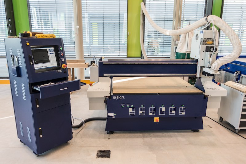
This week we had to do some big-size computer-controlled machining. Due to the fact that our FabLab does not own a big CNC mill, we went the 34km to our friends from the FabLab Kamp-Lintfort.
12

13
At the FabLab Kamp-Lintfort, we had access to their Easy Worker MasterPro 2513 CNC mill. For my project, I used a 6mm end mill, which was supplied by the FabLab. So there is no real additional information on this.
14
15
The CNC is equipped with a really nice feature. The complete milling area on the machine bed is constructred as vacuum table. On this table, there is a 5mm MDF board as sacrificial layer and the vacuum is still strong enough to hold a second board while milling upon it secure.
The vacuum is holding the second board through the fibers - there are absolutely no holes in there. This was very impressive. The table is divided in 6 different sections, which can be used independently from each other.
16
17
For this assignment I had to decide which material I wanted to use. Instead of using the FabAcademy-standard OSB board, I went to my local wood supplier Holz-Leineweber and bought some multiplex birchwood boards, because I like their very special layer structure. It is a very stiff sort of wood and even water resistant glued. I bought 2 different boards, one with 21mm thickness and one with 15mm, as Karsten from FabLab Kamp-Lintfort told me that he does not know if 21mm will be milled with success.
18
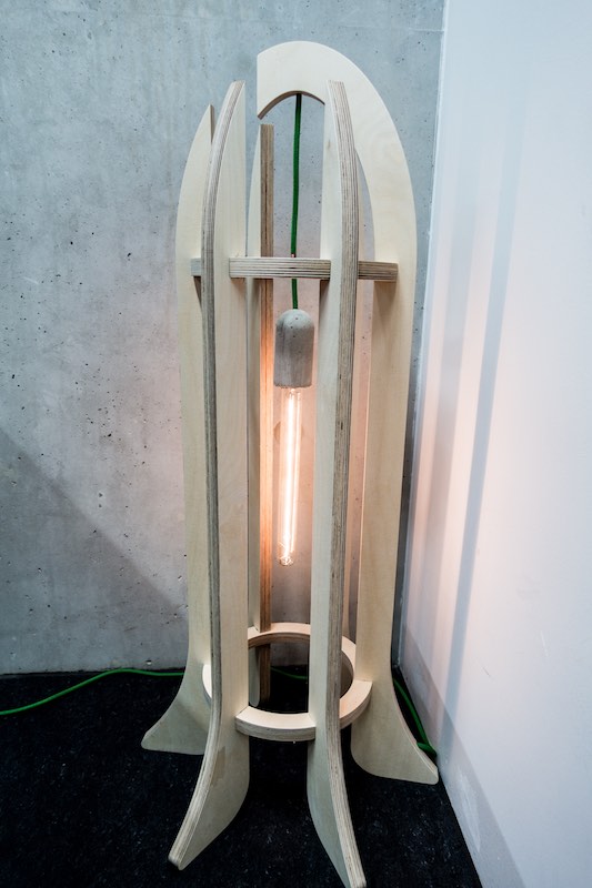
I thought a long time about this assignment, but I had no idea what I should do. After a long day in my office - this must be on the way home - I had the idea to create a lamp with some parts I ever wanted to use in one of my projects. I really love those carbon filament lamps and wanted to use them for years, but there was not enough time. So, I decided use them with a neat free-hanging lamp socket.
While surfing on Amazon the early morning (must be 4am), I found this very expensive but absolutely nice socket, which is crafted out of concrete. As multiplex birchwood boards were used as concrete formwork, I thought that this is the right socket for my project. Due to the fact that the task was to "make something big", I had to scale up my idea and decided to buy this 300mm long carbon filament lamp.
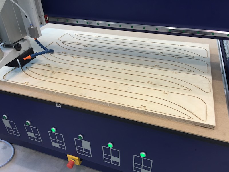
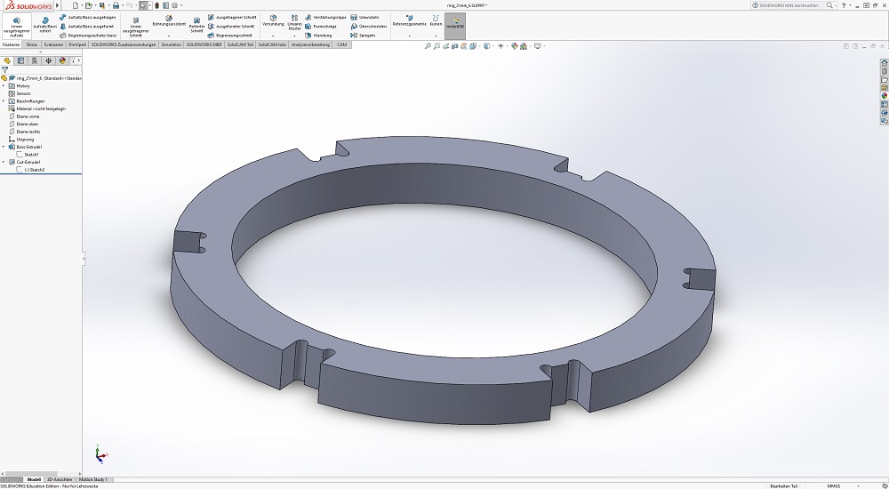
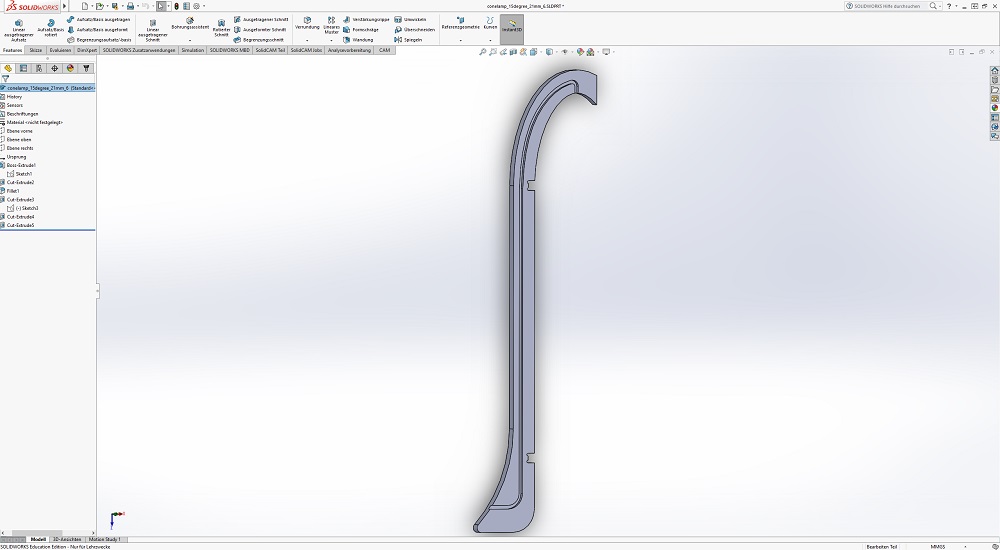
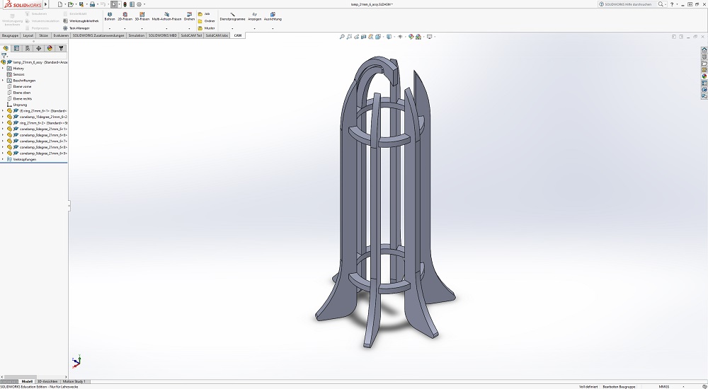
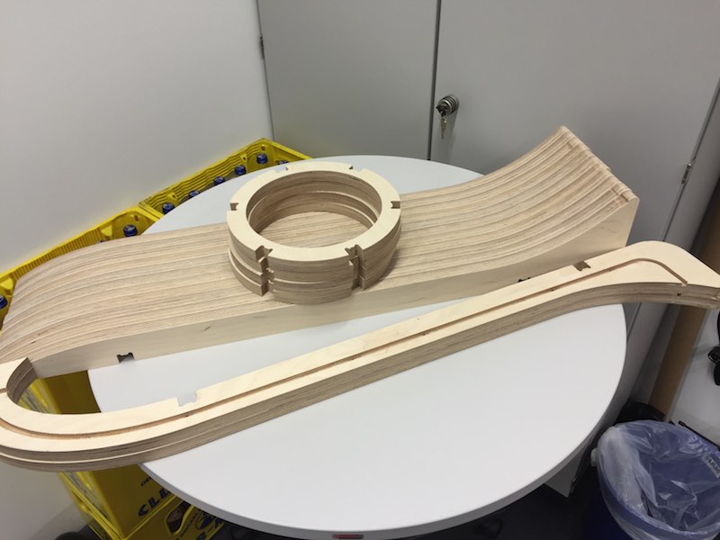
To realize the "something big" in this assignment, the thing must be big enough to not fit on small CNC mills, like the Roland Modela eg., so the over-all size of my lamp is 1000mm in height and a diameter of 470mm. My design is just the first idea I had. Nothing special about this. The cone is designed as whole ellipse, which got a straigt cut on five of six arms. Only of the six arms got a - from the middle - 15 degree extra of the ellipse. This is the arm, which holds the cable in a milled slot and functions as lamp socket holder. The lamp is correctly aligned in the middle of the lampe, so there - under the right conditions - there must be a absolutely indentical shadow to each side. The six arms were aligned by 2 rings, which were designed to join the inner surface of the arms, that there is no edge or cut on the inside of my lamp.
These 3 different parts (five 0 degree arms, one 15 degree arm, 2 rings) were designed with a joint which the CNC mill in Kamp-Lintfort was able to machine. In every inner edge, the CNC mill needs a dogbone with the radius of the actual used tool. In my case, we used a 6mm end-mill, so my dogbones were designed with a radius of 3mm. Feel free to change these values, to mill your own version of this lamp.
19
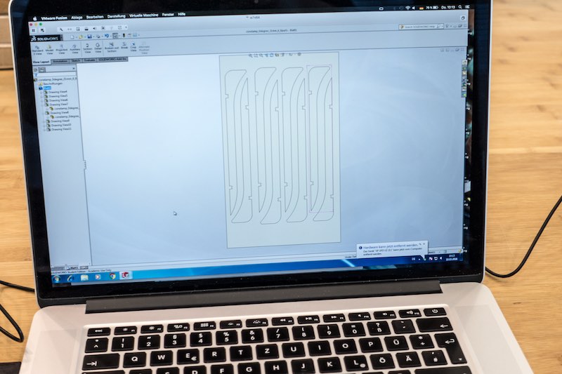
Download my SolidWorks model files as zip
20
The first step was to design the inner ring. This part is a symmetrical ring with 6 slots to fit the arms.
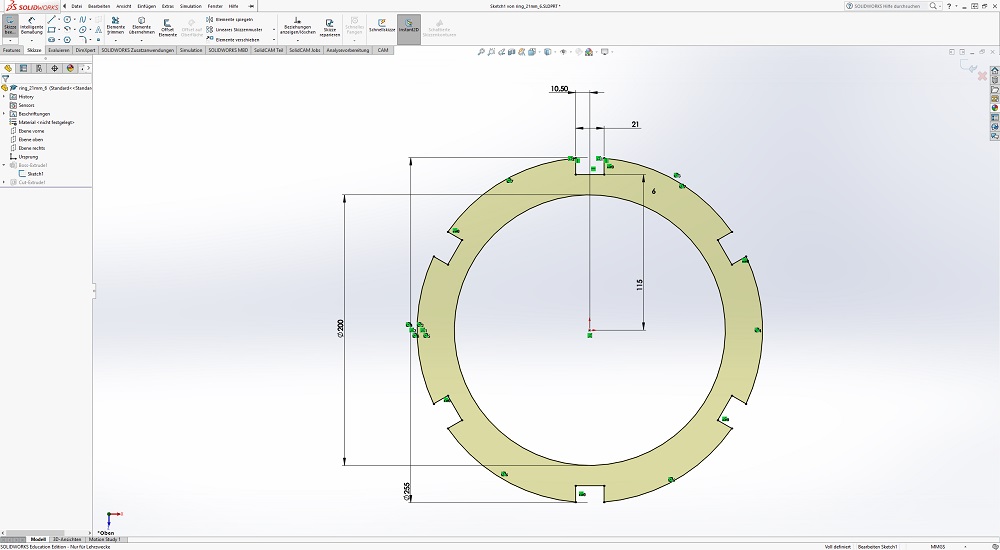
The needed dogbone for the endmill must be added as cutted polar option to all 6 slots.
The finished part.
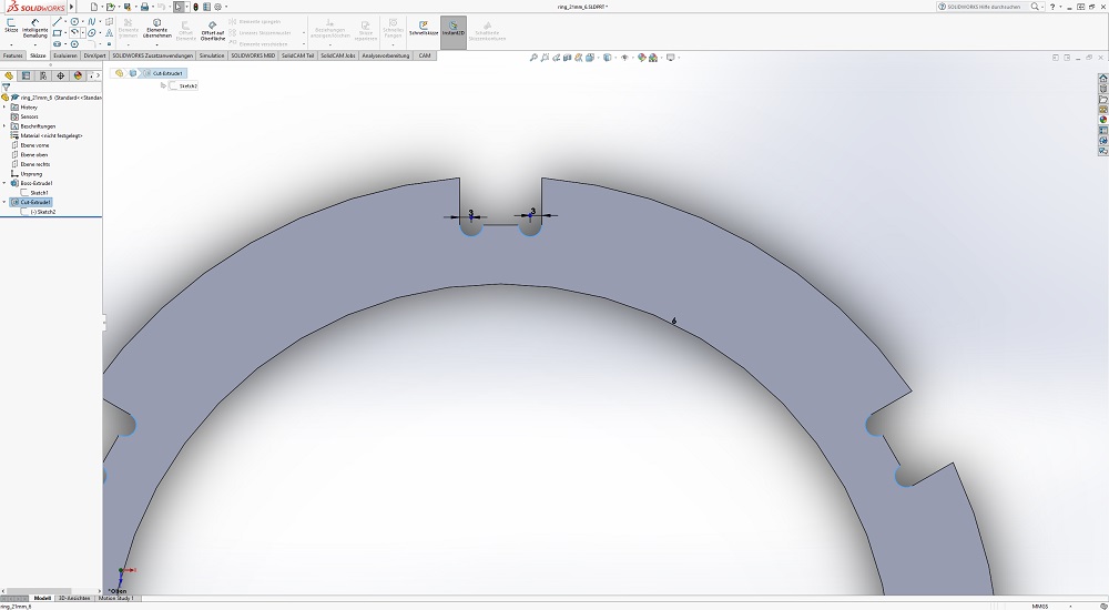
The second and third part are the two different types of the arms. The 0° design is without cable slot and shorter, the 15° design is with cableslot and reaches above the middle of the whole lamp, to center the bulb in the middle.
I played a lot with the design until I found proper "something-big" dimensions. The arm is a simple part. I'll show you the 15° design with cable slot. The lamp is 1000 mm high and 500 mm wide. The 15° design is shown on the picture. This is the enlarged arm angle. I cutted the edge straight down, later. I'll show you the 15° arm as example.
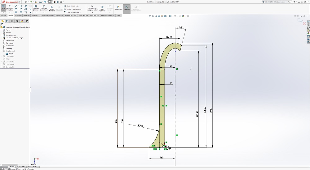
The next step was to cut out the slots and dogbones to fit the rings. The slots are important as I wanted to align the rings to the arms, without any embossment on the inner side, which could cause any shadows.
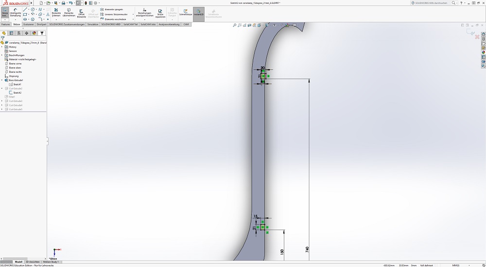
The last step was to cut out the cableslot. I designed the slot with offset from the inner contour with the width of the used cable.
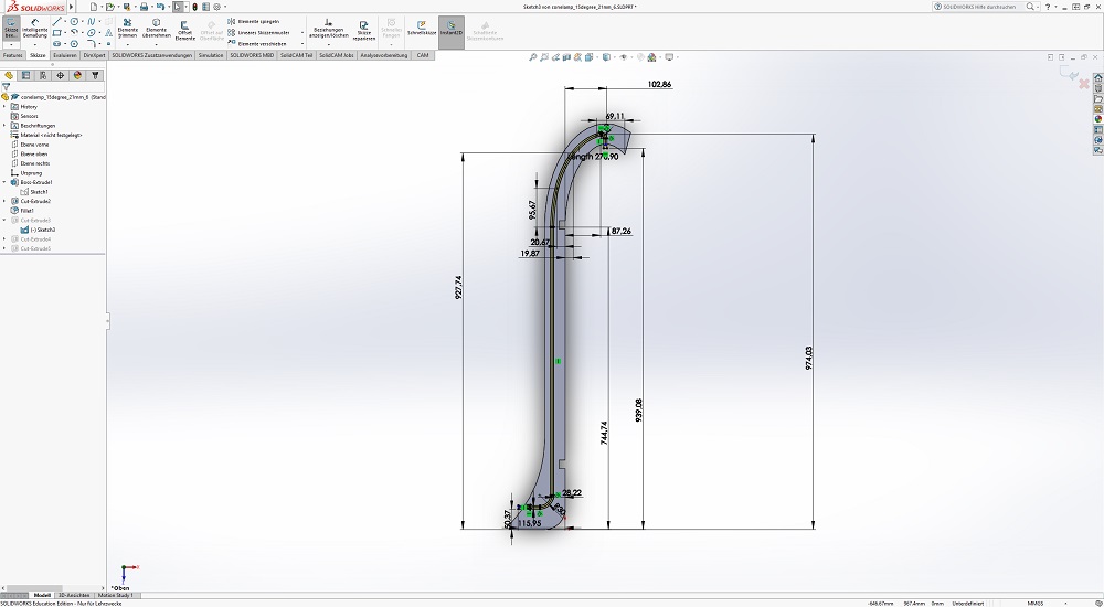
The finished part.
The whole lamp with 5x 0° arms, 1x 15° arm and two rings assembled.
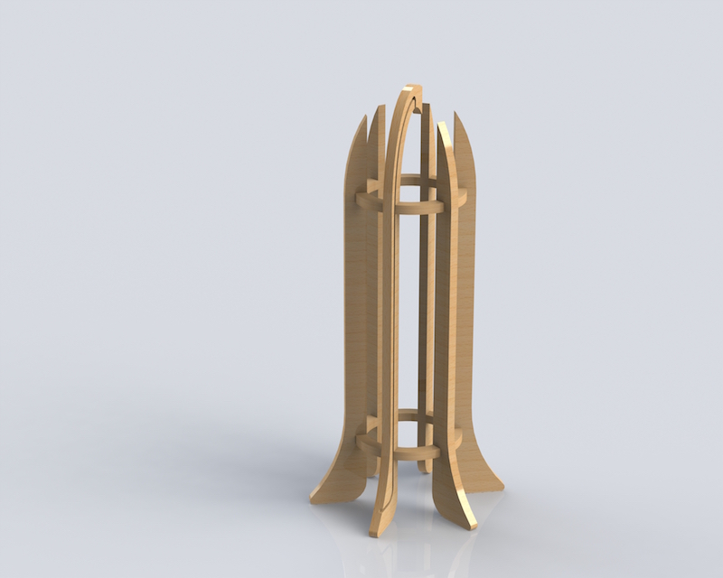
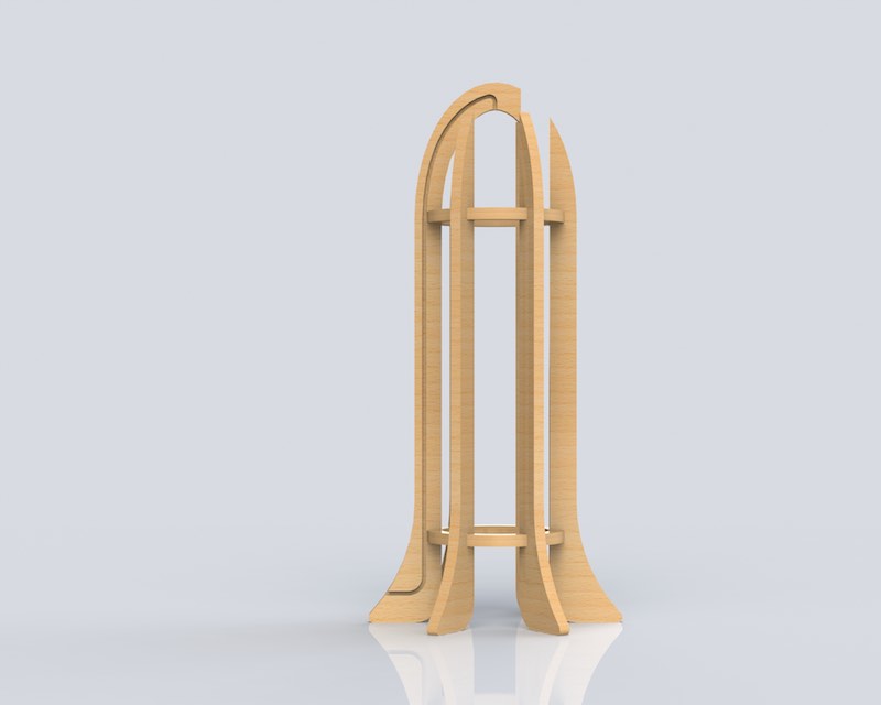
Here is a SolidWorks rendering of my lamp design :)
21
22
23
While milling my parts with Karsten, he started a nice tutorial for their CNC mill, which might help other - and ourself - a lot, when it is time to use their mill again.
24
Karsten introduced me to their mill first, then we started milling my project.
25
The first step was to align the parts to be milled. The CNC mill need (like the most other mills...) 2D DXF files. To generate them and align the single parts, I used the drawing tool from SolidWorks. The important thing is to set the right options. Import the parts in 1:1 scale, the projection must be set on true (no projected surface, angle eg.) and the quality should be set on high. Export the DXF after aligning the different parts.
26
27
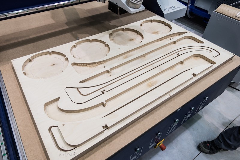
As second step, we put a multiplex board on the table and aligned it correctly. The CAM program recognized all the paths correctly, but the CAM processor is a real pain. It only reads old R12 DXF files (but this could possibly fixed with an update, Karsten told me that they never made an update...). The CAM processor needs per machining step a single layer in the DXF file, which was a real problem for me in SolidWorks. I made the model the days before and travelled to Kamp-Lintfort to get the last information to create a DXF the right way.
The first sheet (my 0 degree arms) was no problem. There was just outline milling. This sheet was a single layer and the program recognized everything correctly. But my second sheet made some real problems. I was not able to convert my inner cuts to a second layer in SolidWorks. This took my 2 hours in SolidWorks without any success. Karsten told me that he used Adobe Illustrator some weeks ago and it worked without any problem. I tried this - and we both stood weird looking in front of my MacBook. I don't know why even this did not was the solution. Illustrator was not able to export the DXF correctly. After this, Adriana helped me a lot with Rhino to solve this toolchain f**kup. She was able to change the lines which must be added to another layer. After this, I was able to mill my boards.
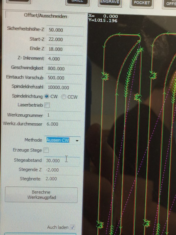
Karsten gave me some reasonable values for their mill and tools which we used for my project. As of the problem that this is not our machine and there was not that much time to check or evaluate these values, I had to use them without checking by myself if they are good for this material and my design.
28
29
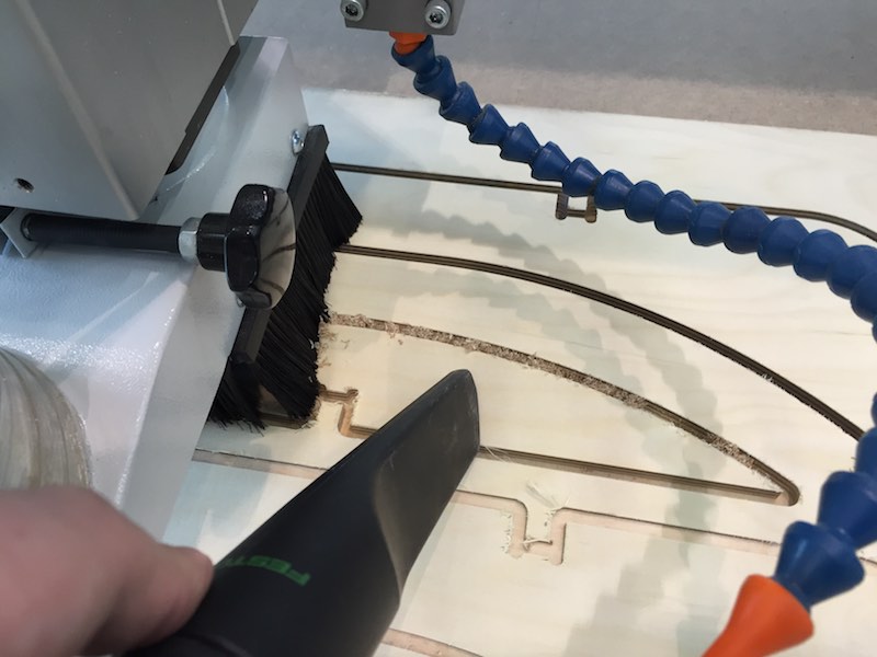
With the values supplied by Karsten, the mill was not that fast, but there was even no risk to break the end-mill. While milling I had to use the vacuum cleaner to clean the milled path, as the integrated extraction equipment was not able to remove all shavings.
30
31
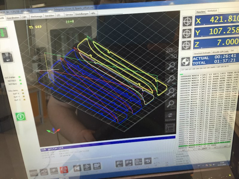
While milling, the CAM program showed the actual stats like elapsed and remaining time, the positions,the generated toolpaths and the actual used code. This is very helpful to notice a problem before it happens.
32
33
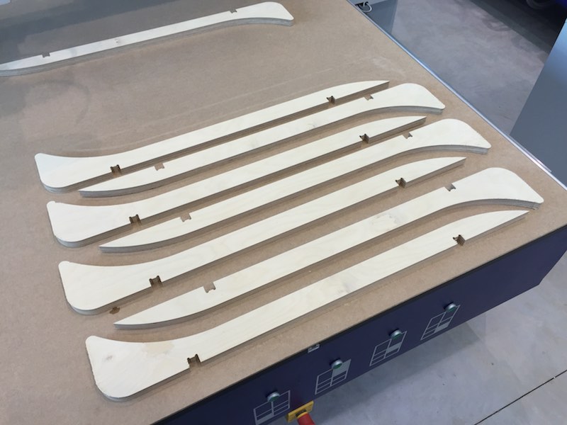
After 1,5 hours of cleaning, waiting and some hoping, the first batch was finished. The vacuum table was able to hold all the single parts while milling.
34
35
The second board which I had to mill was - as mentioned above - a little more tricky. After the problems with the CAM processor, we had the problem that the second multiplex board was not that even and lost suction the vacuum table. As quick fix we used a second, even that expensive, sheet of multiplex and drilled the to be milled one onto the second, which was used as sacrificial layer also. As solution, I would use a bigger sheet of multiplex or apply not that much parts on a single board the next time. After fixing this, the second board was milled with success too.
36
37
After milling all the parts (I made parts for 2 lamps), I had to deburr all the edges. This took me a while. :) But after this step, the resulting parts were very nice.
38
39
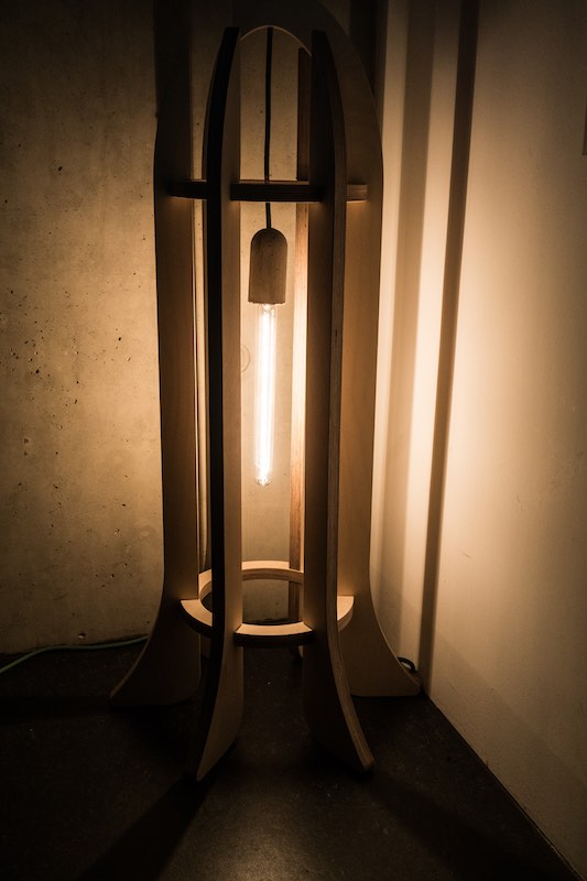
Here are some pictures of my finished lamp...
40
41
... at night. I love this look.
42
43
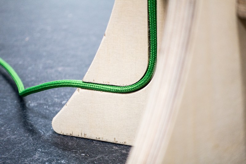
And the lovely cable in the cable slot.
44

This work by Daniel Bruns is licensed under a Creative Commons Attribution-NonCommercial-ShareAlike 4.0 International License.