Task: model (raster, vector, 2D, 3D, parametric design, render, animate, simulate, ...) a possible final project, and post it on your class page
2D DESIGN: Inkscape
Vectorizing raster images with Inkscape
- Open the image in Inkscape, create a new layer for the bitmap image and a layer for the vectors.
Then give the layer a name.
- Select the image and go to Object > Move to Layer
to change the layer for the bitmap image.
Now you can show or hide the bitmap image.
Check the Current Layer: it has to show “Vector”.
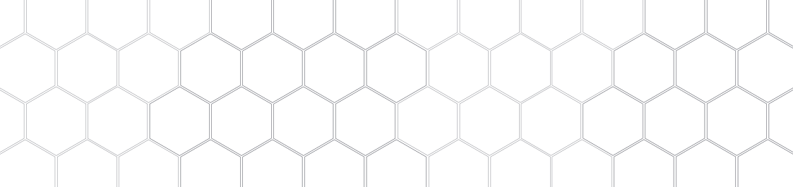
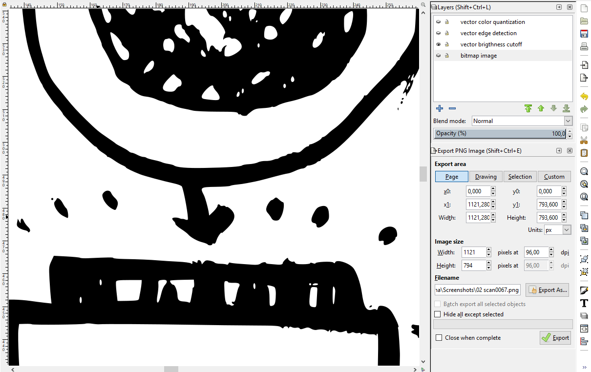
- Select the bitmap image and go to Path > Trace bitmap.
Try the three options to see the different results: brightness cutoff, edge detection, color quantization.
I also try the command Path > Simplify.
It reduces the number of nodes, for example from 17000 to 2000 nodes!
 brightness cutoff
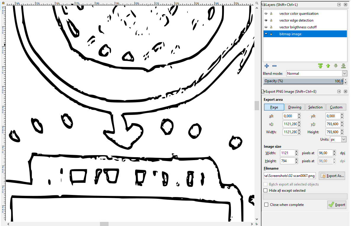 edge detection
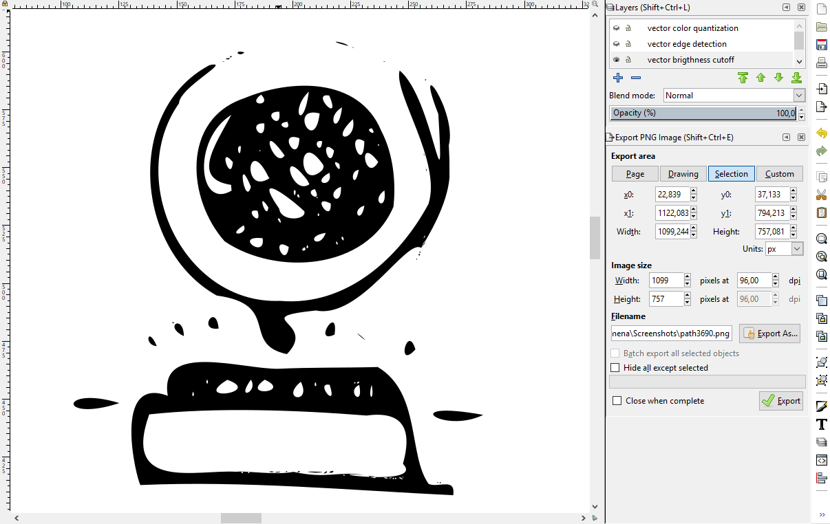 brightness cutoff + simplify
 Cloning vectors with Inkscape
To clone an object in Inkscape, first select the object and go to
>Edit >Clone >Create Clone (Alt+D)
If you have many clones of an object and want to know which is the Original object go to >Edit >Clone >Select Original (Shift +D)
Inkscape has an interesting feature: Tiled-Clones. It is another way to clone an object and create a pattern at the same time. To open the 'Create Tiled Clones' window go to:
>Edit >Clone >Create Tiled Clone.
I want to create a pattern with larger tiles in the center of the circle.
The size of the tiles depends on the opacity of the background (in this case the gradient fill).
The greater the opacity, the larger the tile is.
So I draw a circle with no outline but with a gradient fill, then the object I want to clone (in red). I select this object and go to
-‘SHIFT’ in the Created Tiled Clones windows. I enter
Shift X: 10 Per column, and Shift Y: 10% per row.
- In ‘COLOR’ I change the color to black.
- And finally, in 'TRACE' I select in '1. Pick from the drawing under the tiles' → ‘Opacity’ and
'Size' in '3. Apply the value to the clones'. Click on CREATE to generate the pattern.
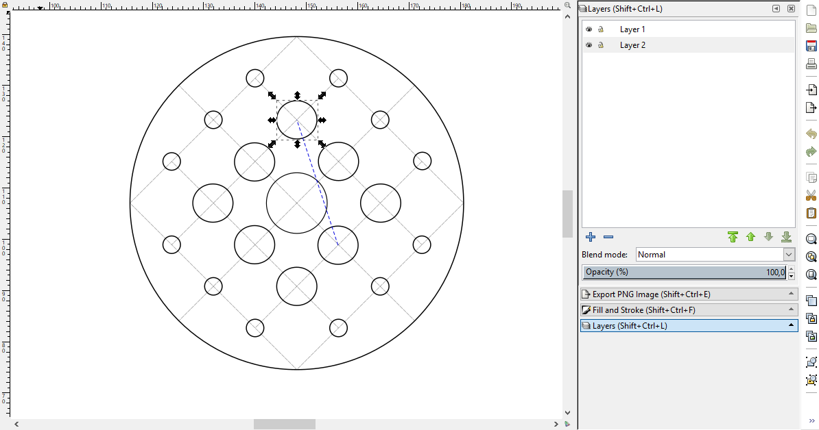 Vector cloning: Select Original
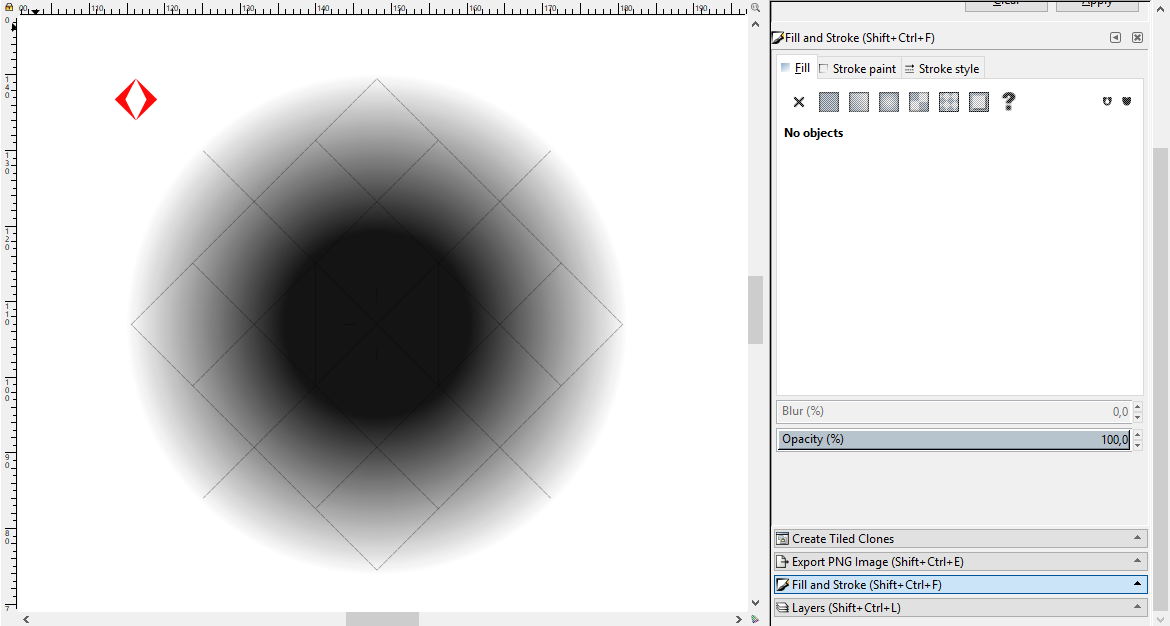 Tiled Clones: object to clone and gradient fill
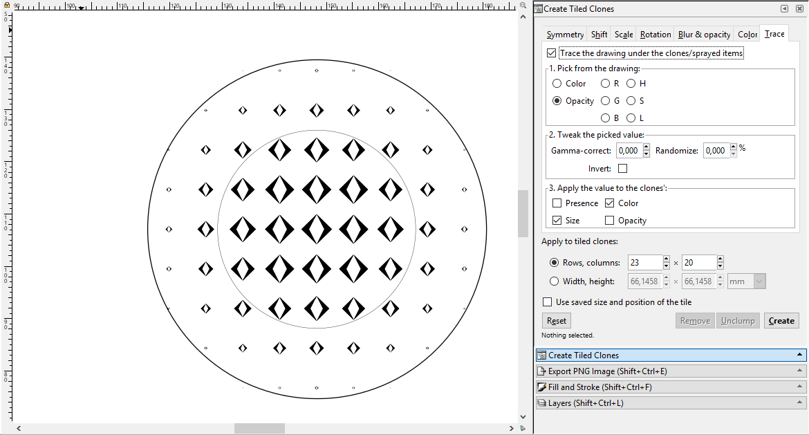 Tiled Clones | result after tracing
 2D DESIGN: CorelDRAW
Vectorizing raster images with CorelDRAW
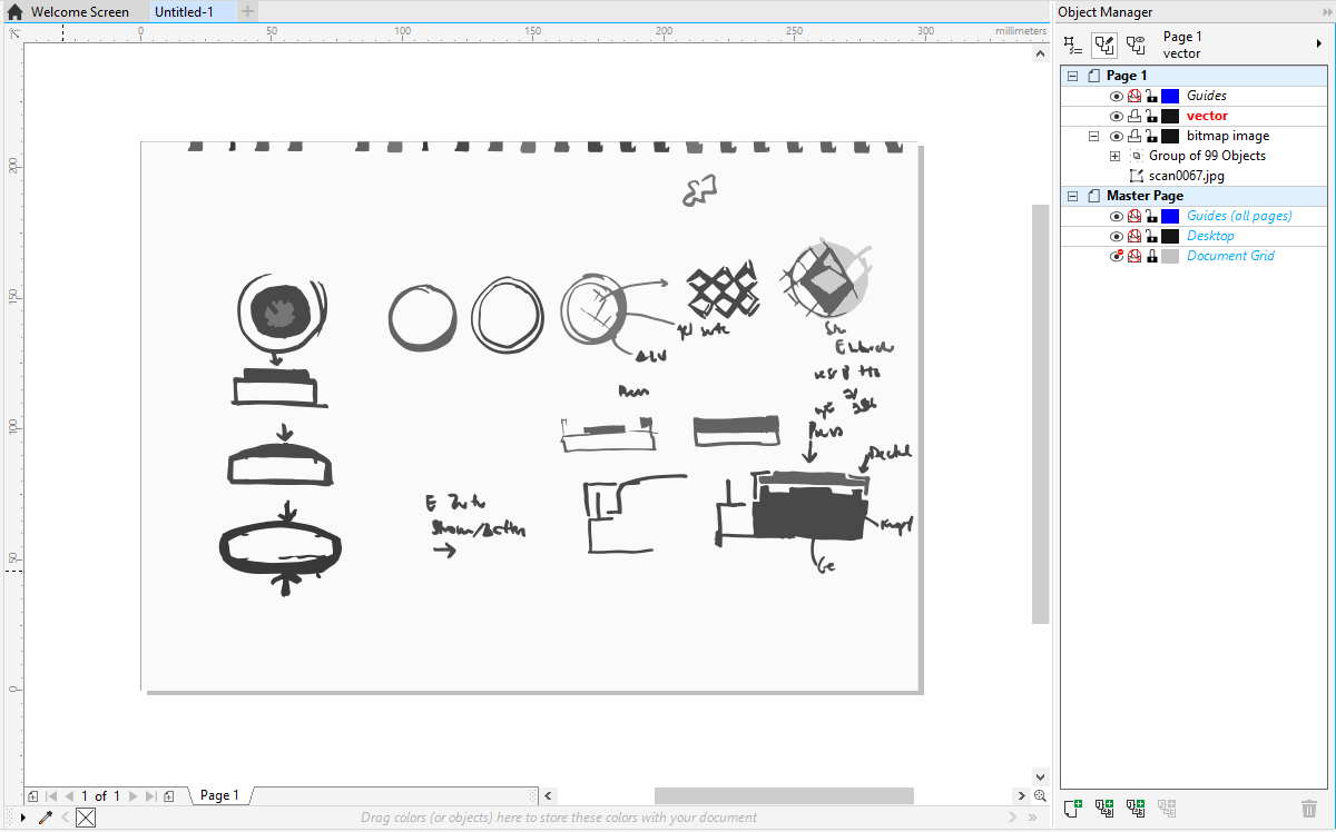
- The first step is to add a new layer in the Object Manager.
Then I test the 'Quick Trace' on the bitmap image. It delivers a very simple result.
I don’t recommend the command 'Quick Trace' on complex bitmap images.
- The 'Centerline Trace' command provides line drawings, that is useful when vectorizing simple graphics, technical drawings or signatures.
- The command 'Outline Trace' gives a similar result like in Inkscape, but in many shades of gray. Corel Draw also lets you filter the colors you want to vectorize.
 Quick trace
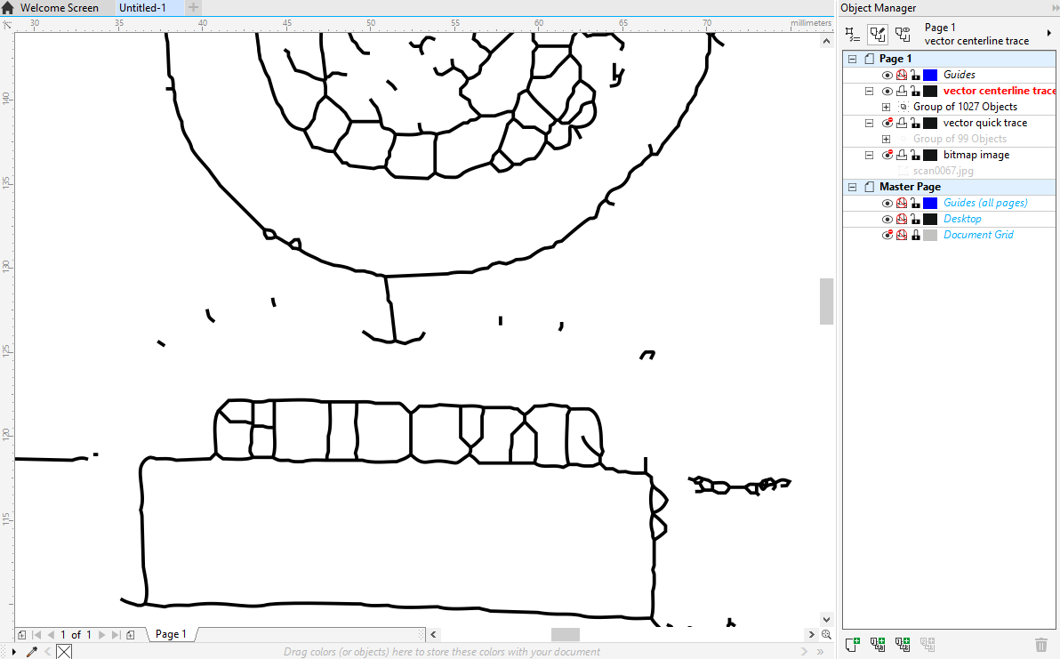 Centerline trace
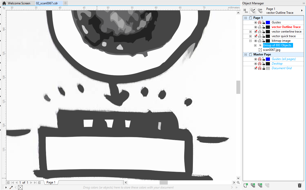 Outline trace
 Cloning vectors with CorelDRAW
I also try the Clone command in CorelDraw
>Chose an object >Go to Edit >Select Clone.
It will create a new clone that you can move or change some properties.
CorelDRAW has an interesting feature:
you can remove the changes made to the clone by reverting to the original or master object:
>Right mouse button on the clone >Revert to master
You can revert these clone properties:
- Clone fill
- Clone outline
- Clone path shape
- Clone transformations
- clone bitmap color mask.
If you want to select which objects are clones, you must first select the master first and then right-click on
> Select Clones in the menu.
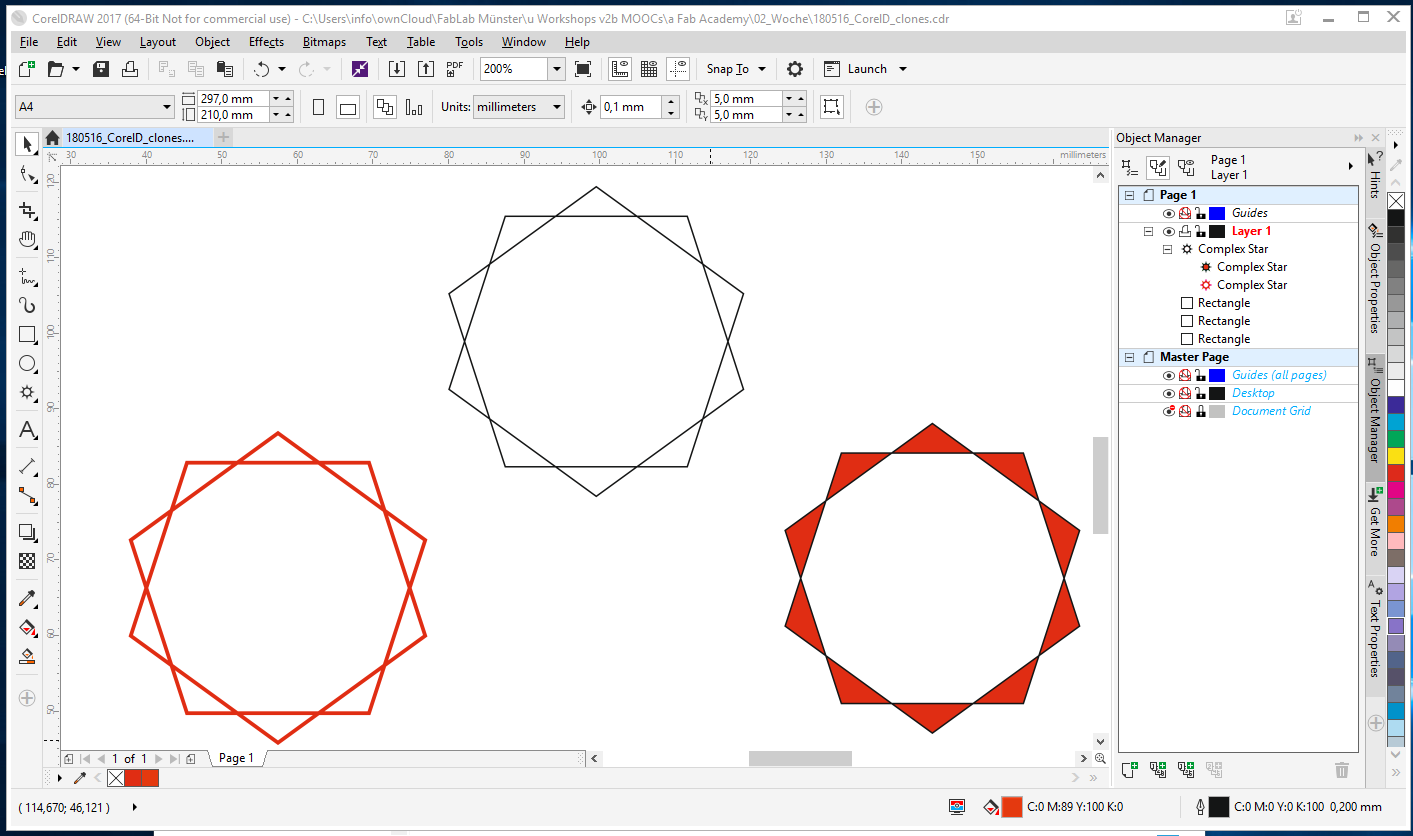 Clone an object and change properties
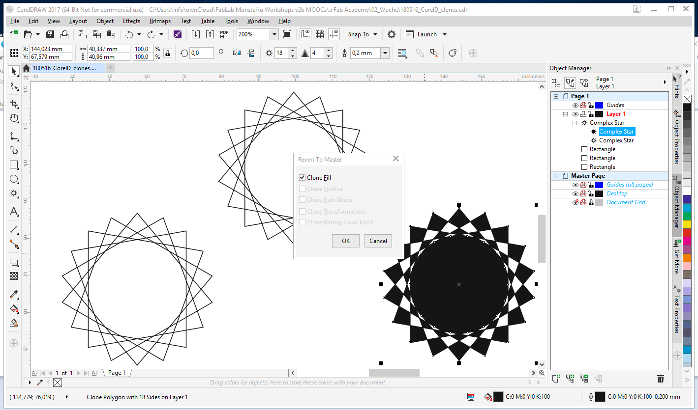 Clone: Revert to master
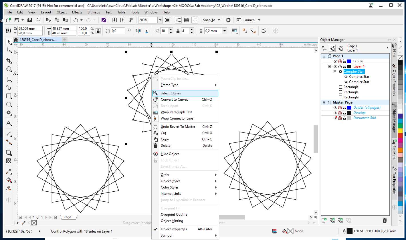 Master: Select clones
 2D DESIGN: Conclusion
Inkscape is freeware and delivers very good results for the Fab Lab projects.
Corel Draw has more options and is useful for use in professional graphic design.
3D DESIGN: RHINO AND GRASSHOPPER
GH = Grasshopper
LMB = Left Mouse Button
RMB = Right Mouse Button
I can draw basic shapes and geometry with Rhino, but I haven’t had the chance to learn Grasshopper jet. So I install Rhino and Grasshopper on Windows because there are no versions for Ubuntu.
Grasshopper is a Plug-In for parametric design in Rhino and has an interface to create algorithms that generate 3D models. You can use it to create and edit complex shapes.
To start the plug-in, you need to type ‘Grasshopper’ in the command line. The interface is really easy to use. You can click on the components and drag them to the canvas. If you want to search for a component, you need to double-click on the canvas and type the name of the component. There are many component groups, I’m just learning the simple ones, like 'Params', 'Curve', 'Surface' and 'Transform'.
For my final project, I will need a case for the Arduino, electronics, etc, but I don’t know how big the case will be. So I decide to start the geometry directly in Grasshopper.
STEP 01
I start 'building' the lid of the case using these components:
'Center Box' and 'Number Slider' for the Y and Z values.
For the X value, I decide to use the operator component 'Multiplication' and the constant 'Golden Ratio' from the 'Maths' group. The length of the box (lid) changes automatically when the Y value changes.
STEP 02
I also define the geometry of the holes with a 'Center Box' component.
STEP 03
… and rotate them around an axis (45°).
STEP 04
Then I link both components with the 'Rectangular Array' component, which is linked with 'Number slider' component (X/Y spacing).
Also for this component you need to specify the size of the array cell with a 'Rectangle' and the X and Y values for the rectangle with a 'Panel'.
The yellow components are panels. You use panels for customs notes or text values.
STEP 05
I move the boxes for the holes with 'Move' from the group 'Transform/Euclidean' and set a new position with a 'Panel'. The default position is {0,0,0}.
STEP 06
Last, I use the 'Solid Difference' component to create the holes in the lid. The input A of this component is the Box_Lid, the second input B are the array of boxes.
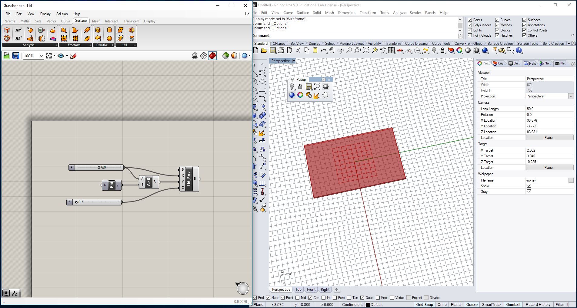 Grashopper Step 1
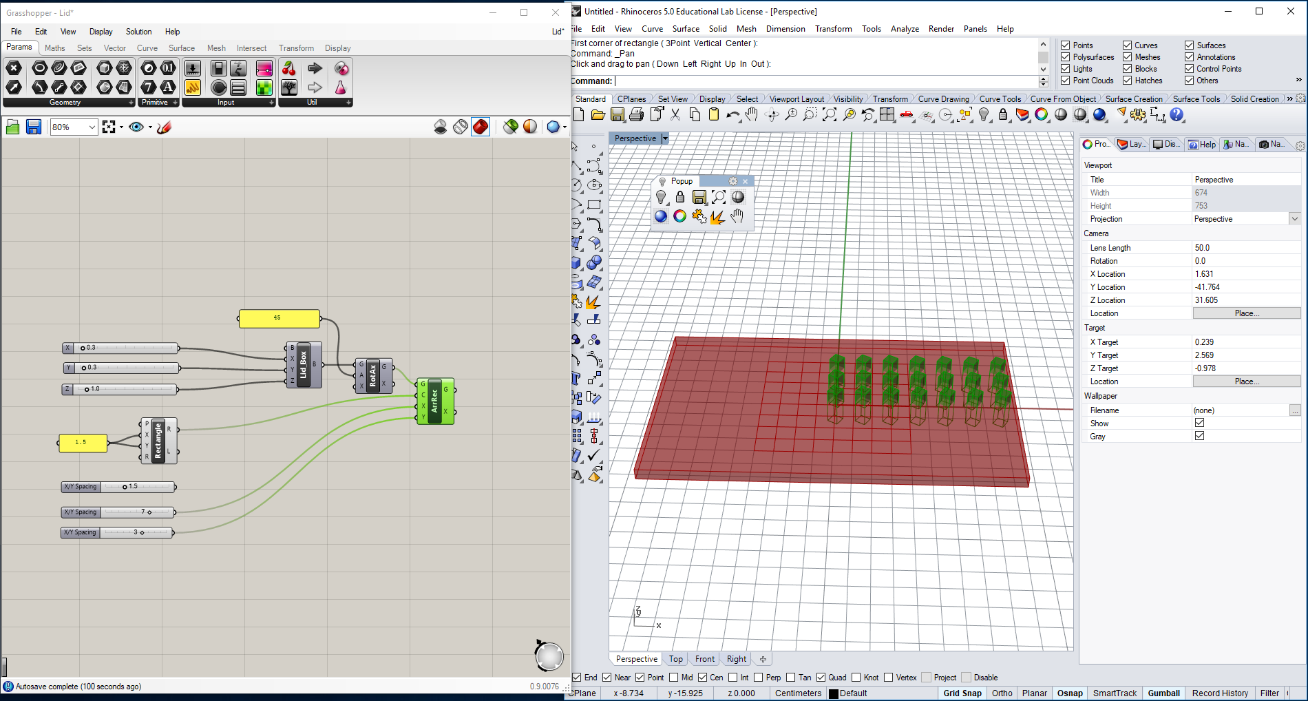 Grashopper Step 2
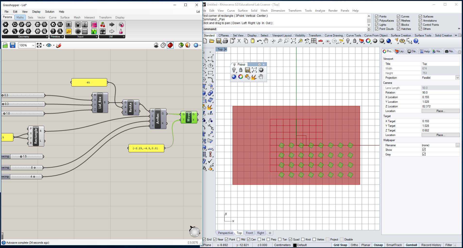 Grashopper Step 3
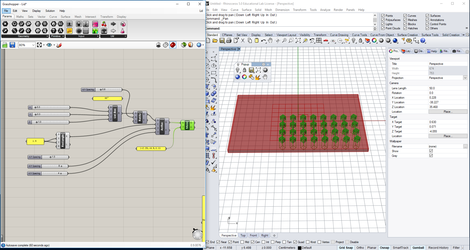 Grashopper Step 4
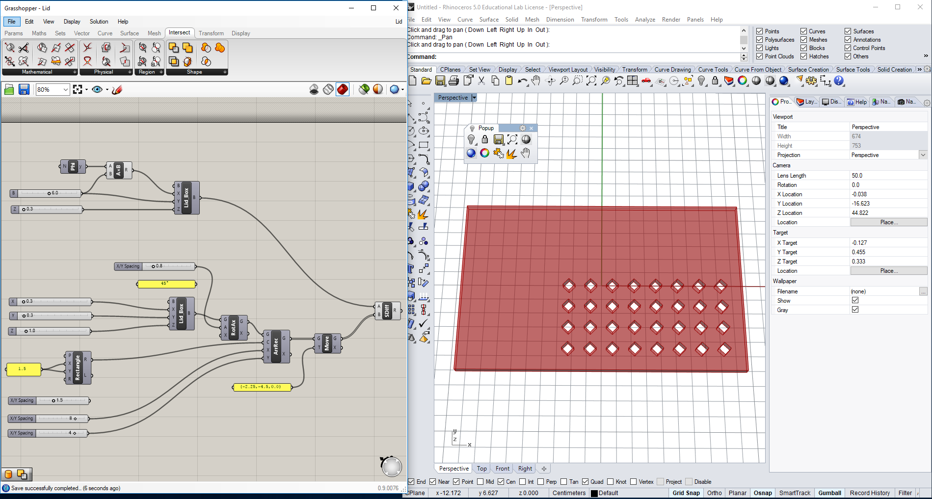 Grashopper Step 5
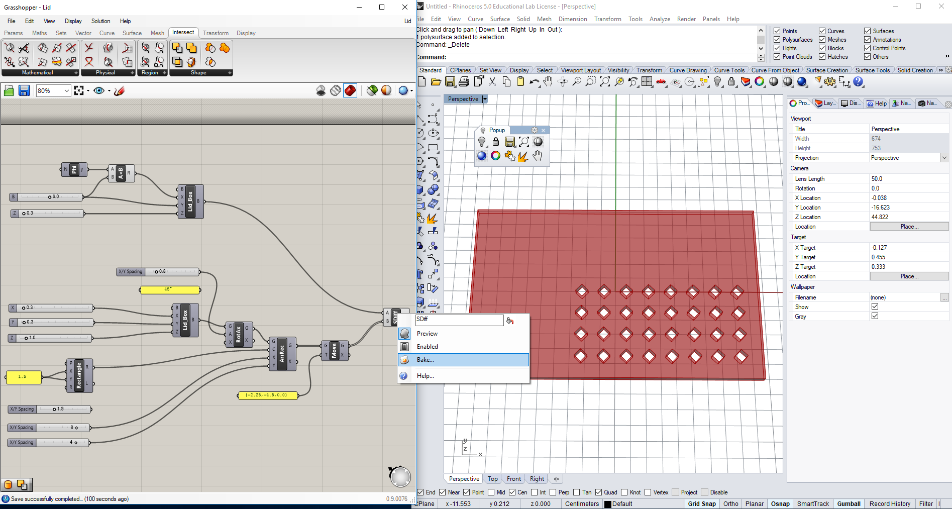
Here is some additional information about GH that you need before you begin:
Grasshopper displays a real time Preview of the model in Rhino. If you want to transfer the model to Rhino, you need to click on it (it will turn green) and 'Bake' it.
> RMB on the model in Grasshopper > bake
After that, a 3D model will be generated in Rhino and you can modify it if necessary.
Render it or export it as a .STL-file for 3D printing.
NOTE 1: you can also draw the geometry in Rhino and link it to Grasshopper.
>LMB on the solid/surface/curve...in Rhino > RMB on component 'Geometry' > Set one Geometry
NOTE 2: It is also possible to embed the geometry in Grasshopper
> RMB on the geometry in Grasshopper > Internalize Data → GH saves a copy of the geometry
 Grashopper 'Bake'
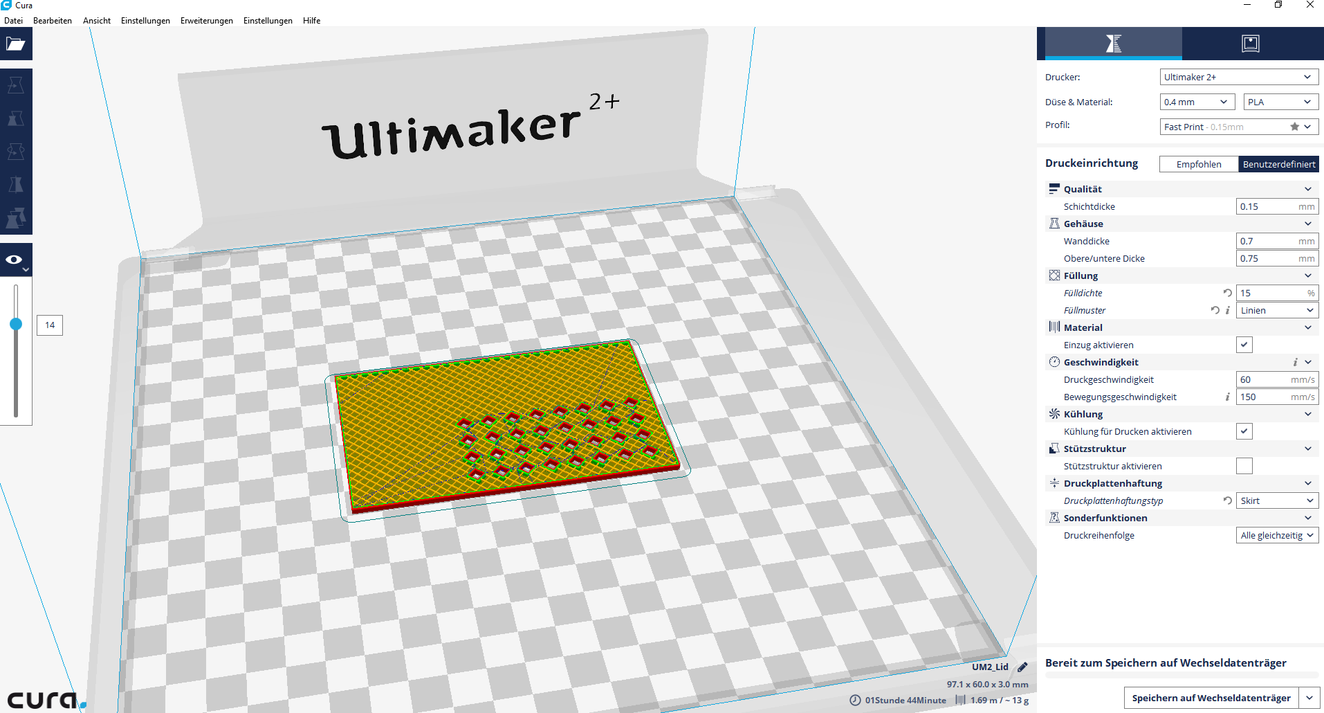 .stl file in Cura
 Warnings in Grasshopper
- color state gray means that something is correct
- color state orange is a warning.
- color state red is an error. Mostly when input data has not been defined.
More information about warnings can be found here:
> RMB > Runtime warnings > 1. Input parameter A failed to collect data …
Rendering with Rhino
For the base station I make a case and render it with the lid in Rhino.
There are default materials you can use in Rhino. So I choose in
>
Properties > Materials > Plastic : glossy and mate plastic surfaces.
The result is not so good because the rendering looks flat. The shadows are too soft. I try many settings but I dot not get the desired result. The next time I’ will try V-RAY, a render plug-in for Rhino.
Tutorials for Rhino and Grasshopper
I recommend these tutorials:
Rhino 5 Essential Training by Dave Schultze in lynda.com
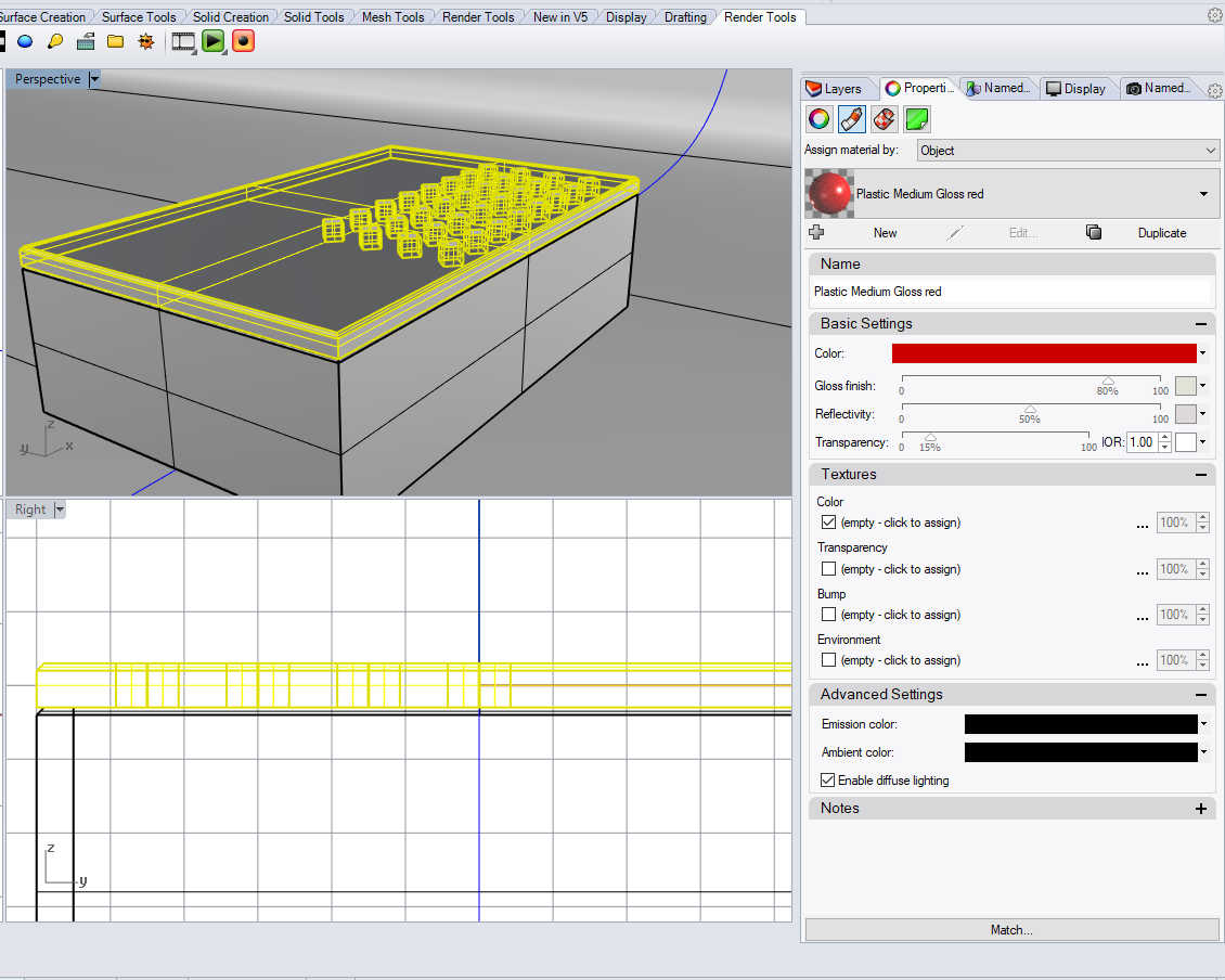 Rhino Rendering Setting
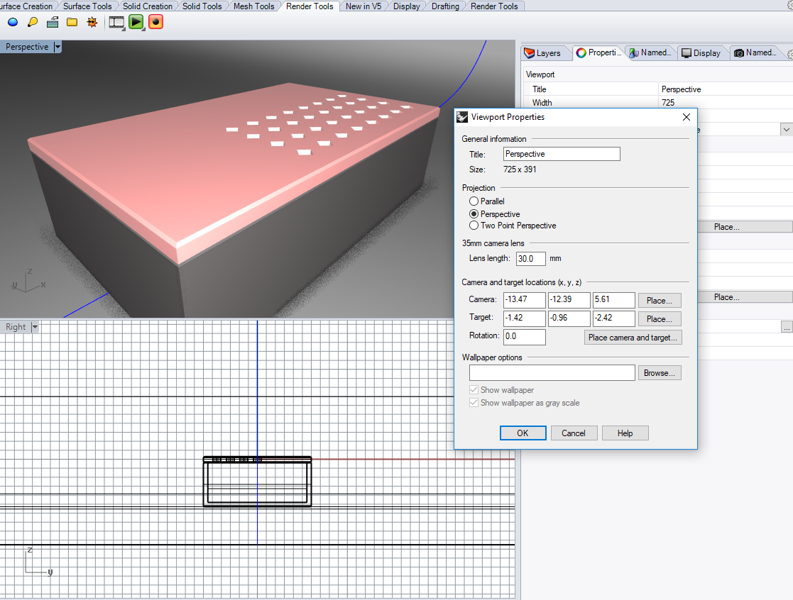 Rhino Rendering
 More tests...
I exported the stl files and made some tests...
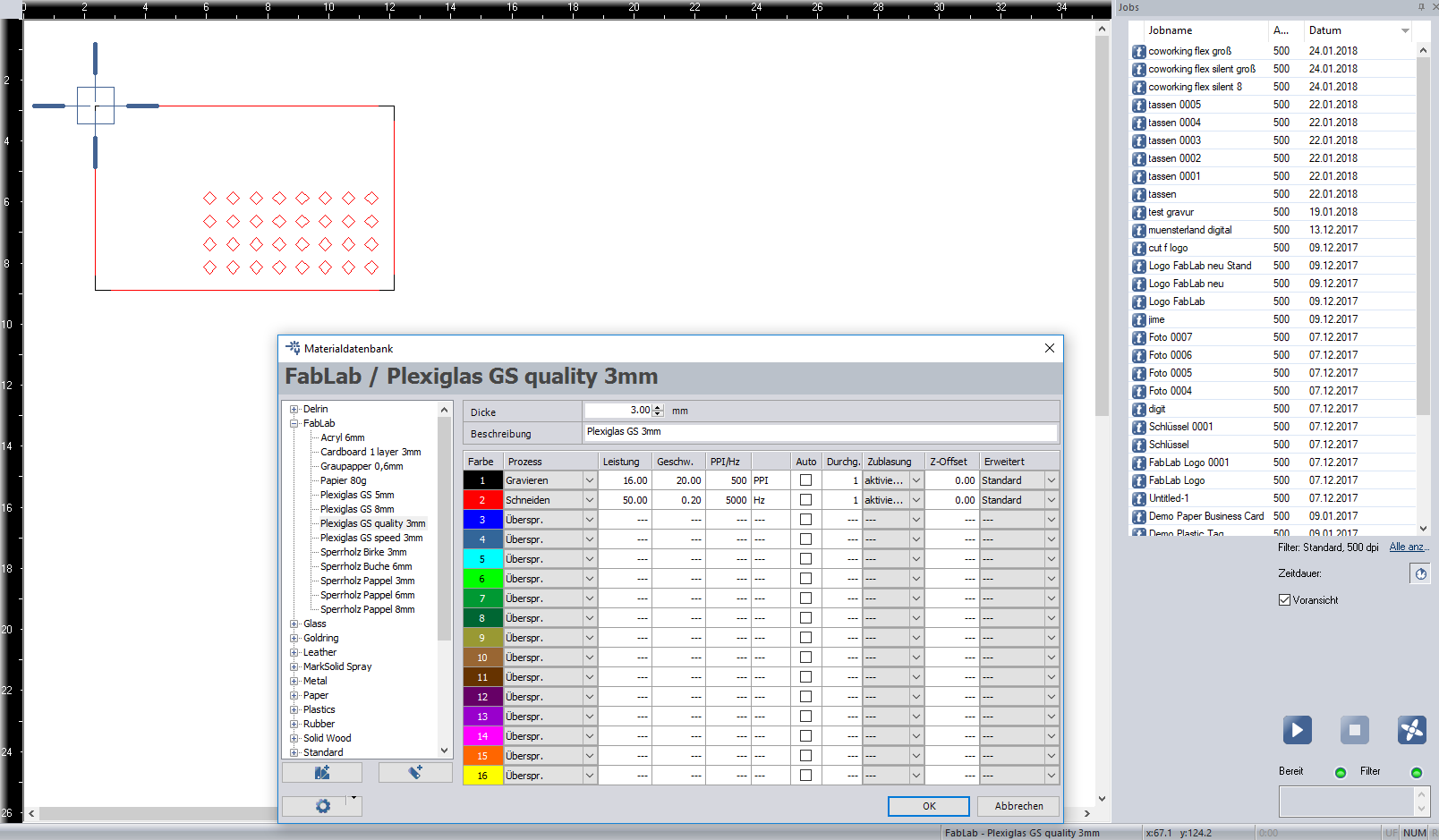 Job Control: Laser Settings
 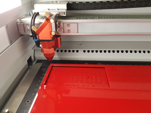 Laser Cutting
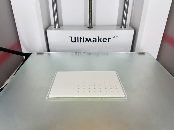 3D Print
 3D DESIGN: FUSION 360
Fusion 360 is a software for 3D-CAD, CAM and CAE. It has a cloud-based platform for Windows and Mac that connects the design process.
CAM = Computer-aided manufacturing
CAE = Computer-aided engineering
Since I haven't worked with Fusion before, I watched Autodesk's "Getting Started" tutorial:
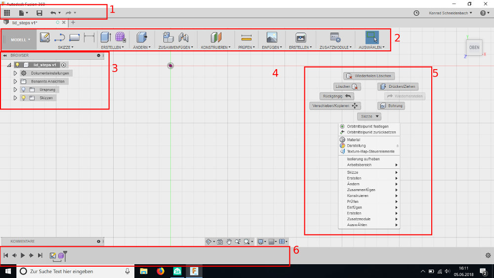
The user interface has these main features:
- the Application Bar (1): to open or save files, undo and redo commands.
- the Toolbar (2): to select the tool you want to use.
- the Browser (3): list objects in your design, for example sketches or parts.
- the Canvas (4): where you make your design.
- the Marking menu (5): contains frequently used commands.
- the Timeline (6): lists operations in your design. You can also make changes in the timeline.
STEPS
- To start a 2D drawing (for example the lid of the case), you must first select a workspace. For a 2D drawing, select Model as a workspace, this is a
very simple project, so you don’t need the other workspaces.
Then click on > Sketch and > Create Sketch to start a drawing.
- The three default planes appear. I choose the XY plane. This means that 3D features will extend along the Z axis.
- Next, under ‘2-Point Rectangle’ in >Sketch > Rectangle I choose the command :
You can set the size of the rectangle by entering the X and Z values.
To switch between the two values, use the Tab key. I use the same command to draw the holes to be cut out in the lid. br/>
- I want to define a parametric constraint between the size of the lid and the holes.
- The height of the lid is d2 : 60 mm.
So I change the height and width of the cut-outs to 'd2/20'. → The result is fx: 3.00 mm.
When I change the height of the lid, the size of the holes changes automatically.
- Using the Move/Copy command, I rotate the small rectangle and place it with a distance of 5 mm from the corner.
- To create copies of the cut-out, I use the ‘Rectangle Pattern’ command.
This command is located in >Sketch > Rectangular Pattern. In the window you can set the number of copies, the direction and the distance between the copies.
- The last step is to create an extrusion of the surface.
This command is located in >Create >Extrusion, then select the surface and enter the height 3 mm (Z Axis). The lid is ready!
 Fusion 360: Interface
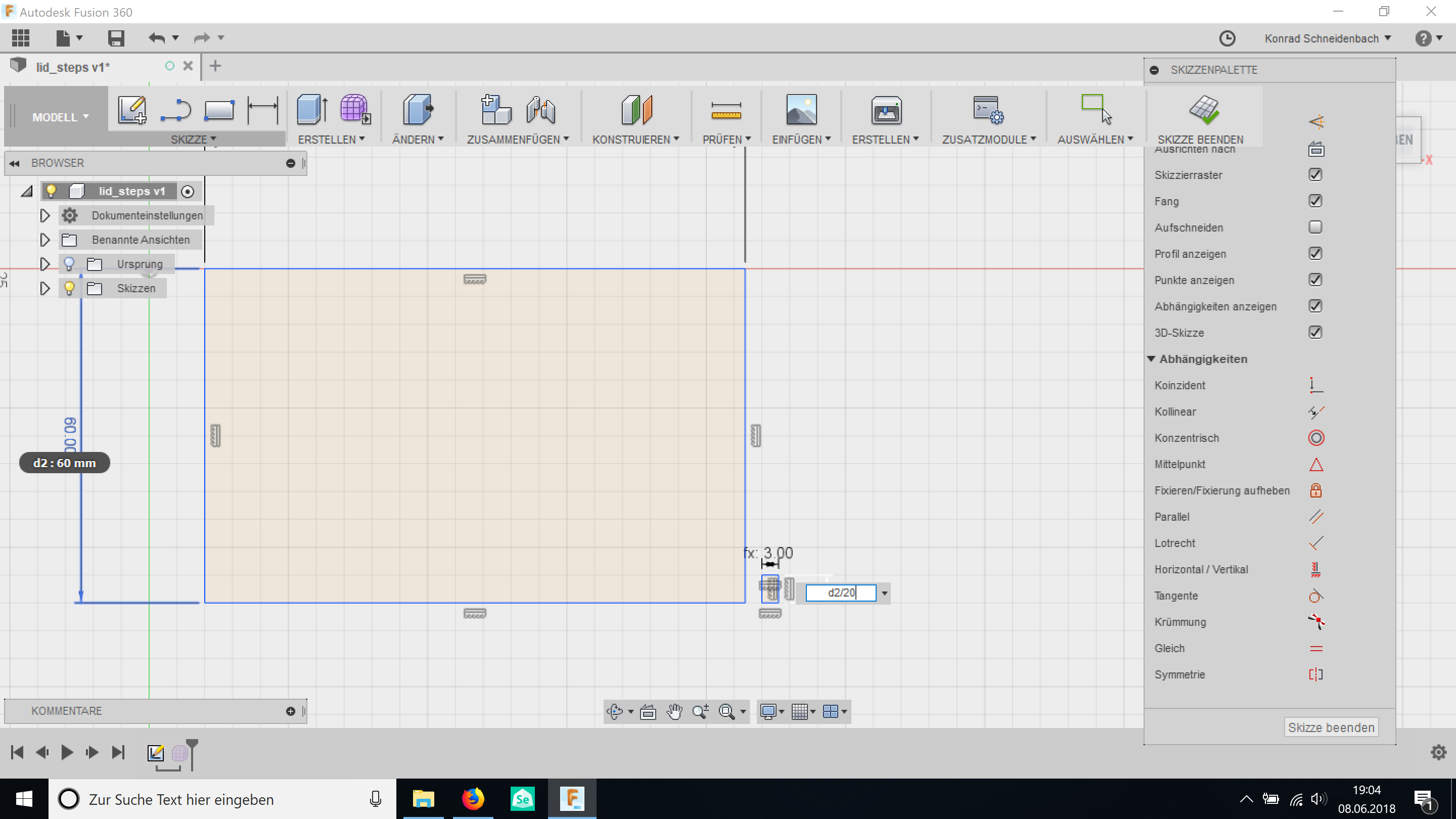 Fusion Parametric Constraint
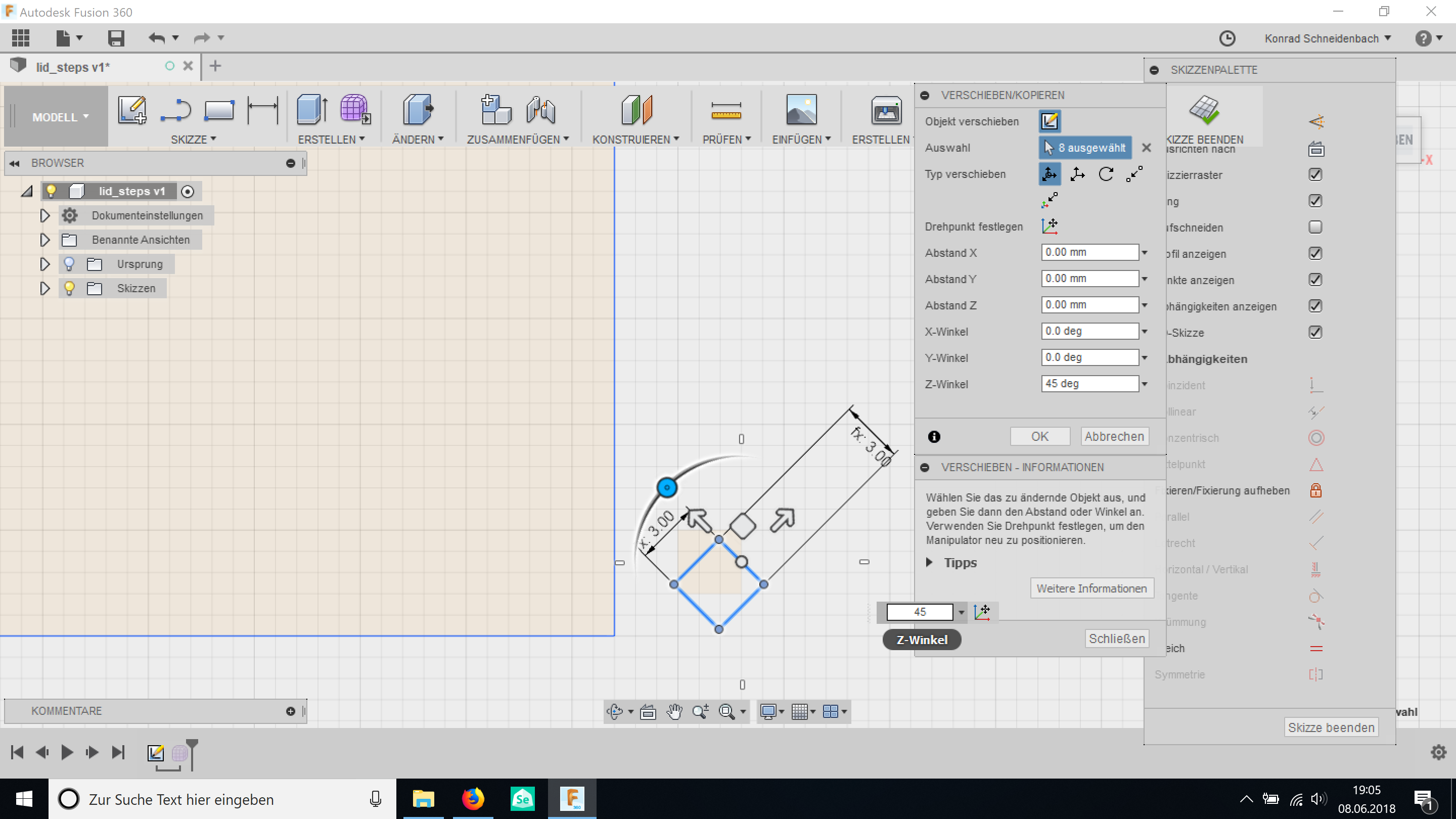 Fusion Rotate
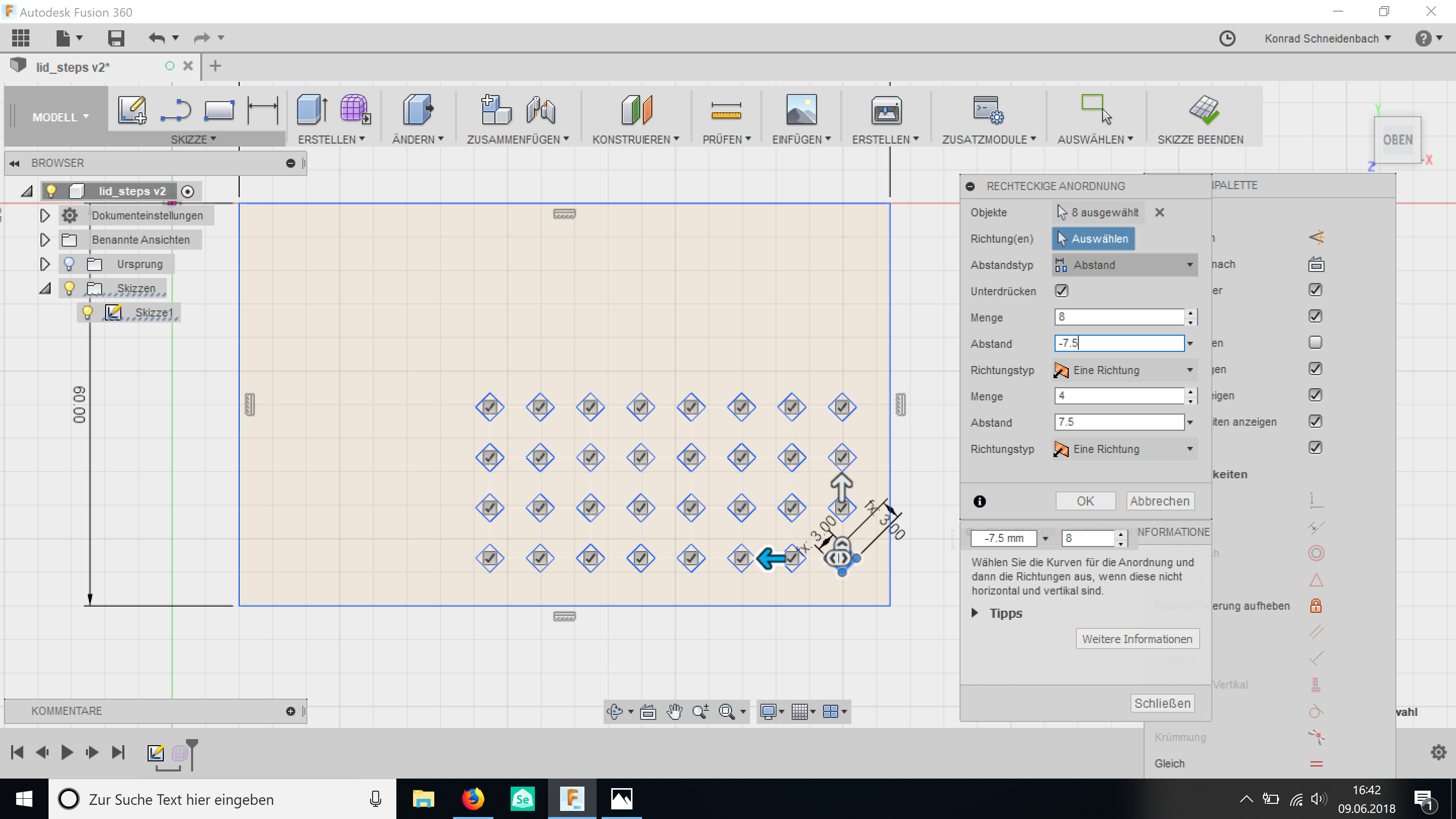 Fusion Rectangular Pattern
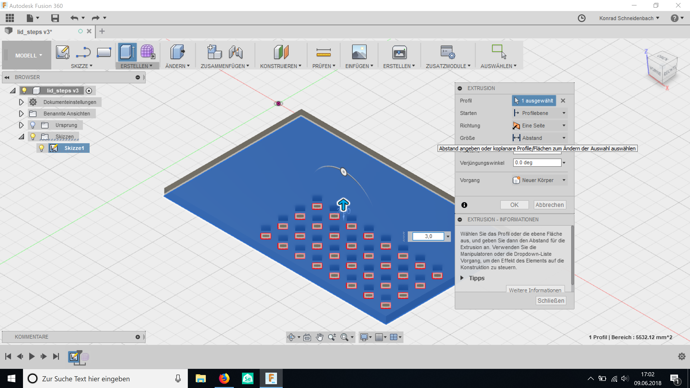 Fusion Extrusion
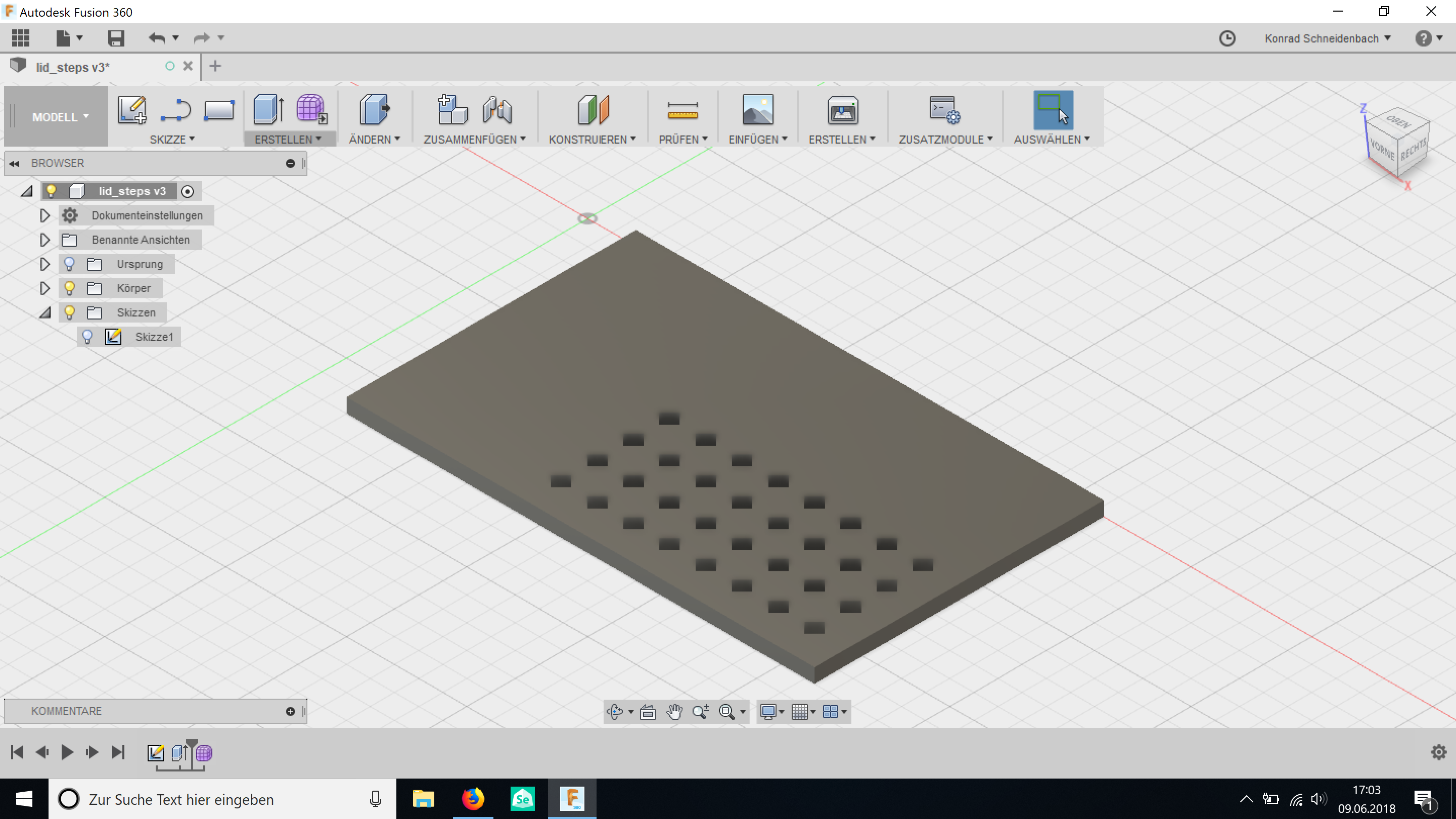 Fusion
 3D Conclusion: Fusion or Rhino/Grasshopper
- The first difference between the two programs is the interface and workflow.
In Fusion 360, you work in one window. Grasshopper is not built in Rhino. A new window will open
to launch Grasshopper. This is sometimes annoying if your screen is small.
- The advantage of Fusion 360 is that it has many powerful tools already built in, for example for CAM, simulation or parametric design.
Rhino: some powerful tools are not built in. For example V-Ray (rendering), Bongo (animation) or Karamba (parametric structural engineering) cost extra.
- Rhino has a simple built in rendering tool. If you want good rendering results, I recommend buying V-Ray. Fusion's rendering tool is more powerful, you get very good results and is cloud based..
→ I liked the interface and the workflow of Rhino and Grasshopper better and will use them for the next tasks.
EDITING A VIDEO WITH Kdenlive
INSTALLING KDENLIVE
- I use Ubuntu. To install the latest stable version, you have to open the terminal and type:
→ $ sudo add-apt-repository ppa:kdenlive/kdenlive-stable
→ $ sudo apt-get update
→ $ sudo apt-get install kdenlive
There are also additional packages that are needed:
→ $ sudo apt install ffmpeg dvgrab dvdauthor genisoimage vlc
EDITING THE VIDEO
I just want to shorten the length of the video and reduce the quality:
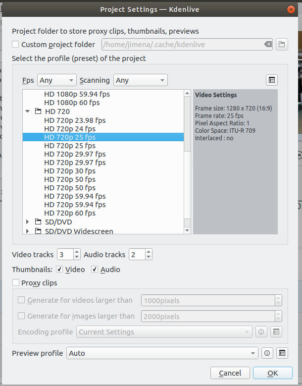
- Open Kdenlive and the go to the menu File > New
- The window Project Settings opens: In 'Select the profile of the project' I choose HD 720p 25fps and click on OK.
- Go to the Project menu > Add a clip and select the clip you want to edit.
- I use the razor tool to trim the video clip and delete the part I do not want.
>menu Tools > Razor Tool
- The last step is to render the video clip:
>Menu Project > Render.
- The render window will open: If it is necessary, you need to change the output file and its destination. Then choose a format: I choose MP4 format and reduce the quality.
- Click on 'Render to file'.
 Kdenlive
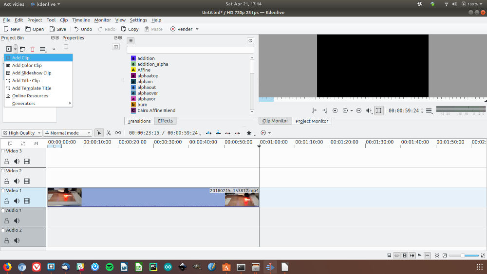 Kdenlive
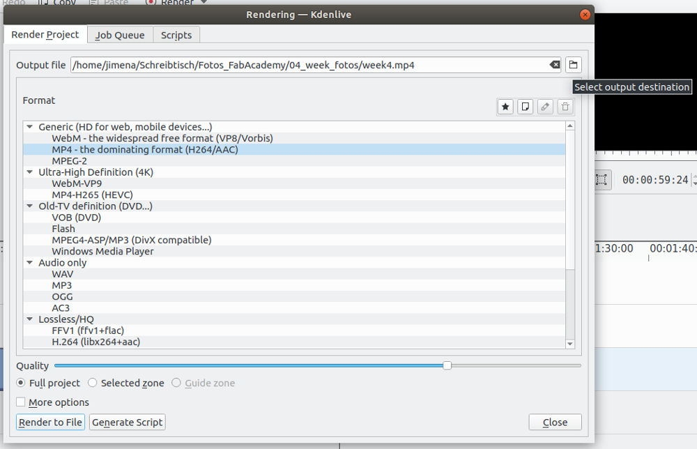 Kdenlive
Download
| Inkscape, CorelDRAW files (zip) | Download |
| Grasshopper, Fusion360, Cura files (zip) | Download |