Task:
GROUP assignment:
-
test runout, alignment, speeds, feeds, and toolpaths for your machine
INDIVIDUAL assignment:
- make (design + mill + assemble) something big
Test runout, alignment, and toolpaths for your machine
MAKING SOMETHING BIG:
DESIGNING THE COFFEE TABLE
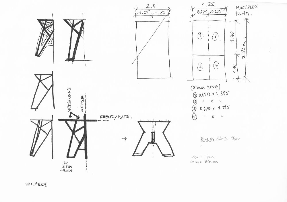
I want to mill a coffee table for the
Fab Lab. After doing some research and checking the ergonomics of a coffee table I start drawing with Rhino.
To build the table I’m going to use a laminated wood sheet with a thickness of 12 mm. The original size of the wood sheet is 2.50×1,25 m and divided it in 4 pieces to transport them in the trunk.
Joints: to assemble the 3 pieces together I choose the t-bone joint. So I draw small circles (R=4 mm) on each 90° inner angle.
I’m using Grasshopper, so I can change them easily with number sliders.
Note: Daniele (instructor in in Kamp-Lintfort) checks my design before I export it. I have to change the radius of the circles for the t-bone joints to 5 mm radius.
The distance between the corners have to be bigger than 6 mm. I can change the radius in Grasshopper without loosing much time.
MODEL:
I make a cardboard model with the laser cutter to check the dimensions of the coffee table and prove all joint are on the right place.
I notice that some circles are missing, and added them in Rhino. .
 Sketches
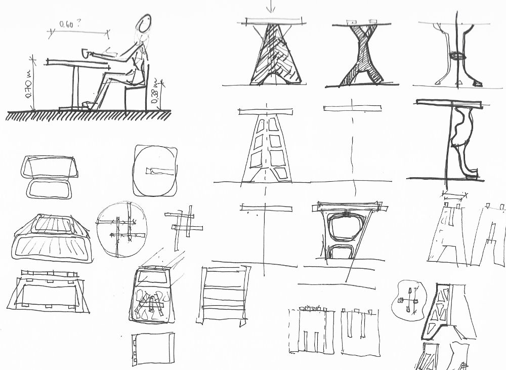 Sketches
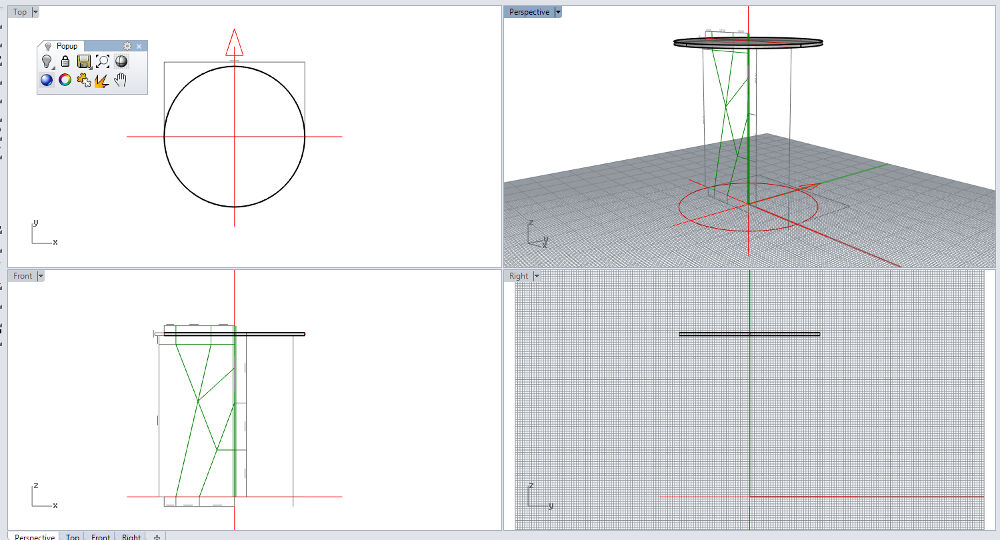 Designing in Rhino
 Designing in Rhino
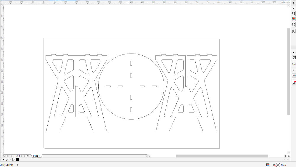 CorelDraw: file for the laser cutter
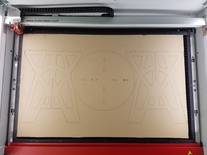 Cardboard Model
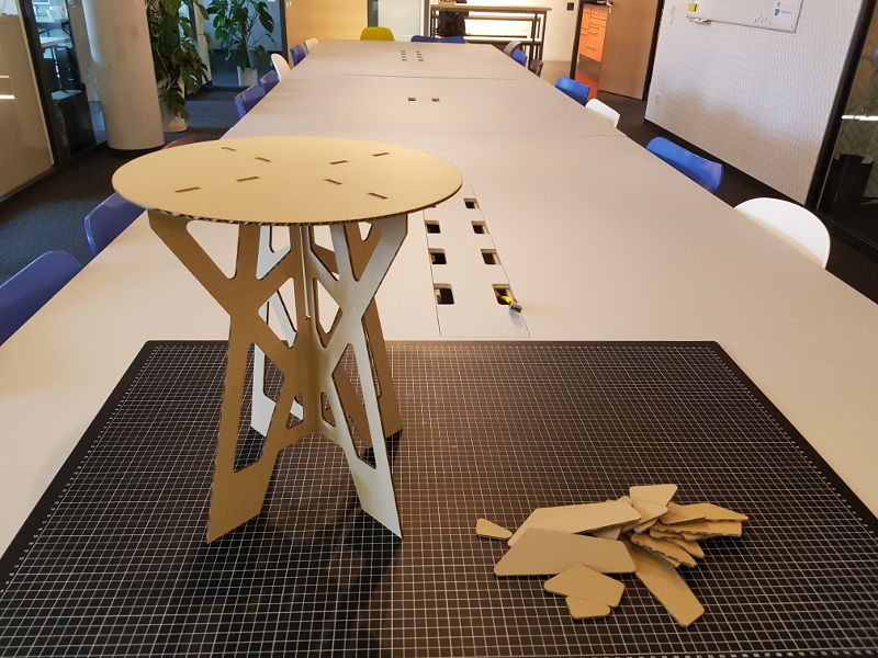 Cardboard Model
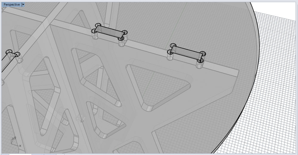 Joints
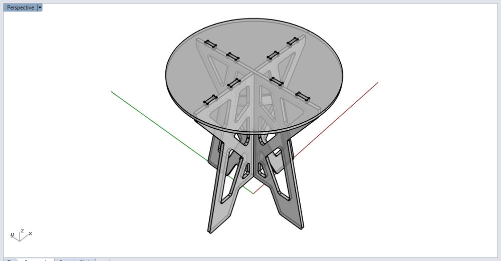 Coffee Table (Rhino)
DESIGN RULES | PREPARING THE EXPORT
FILE in RHINO
Here I will resume the check rules Daniele told
us in Kamp-Lintfort:
- No overlapped lines: check them in Rhino: go to >Select and then >Select Duplicated Curves. Rhino shows the overlapped lines yellow. Now you can delete them.
- No loose lines: you can join loose lines in Rhino by using the command “Join” and then click the lines you need. The lines have to build a closed curve!
After that, I would move the closed curve to another layer.
- I add 3 layers for the export file: outlines, inlines and wood sheet. If you are going to engrave, you have to add one more layer. Daniele (instructor) explains us how many layers we need for the CNC software. I assign each layer a different color.
- If you import a DXF file from Fusion360, you have to prove that there are no tiny loose lines or points in your file. Sometimes you don’t see them on the screen. After moving the closed curves you to need to delete another layers, click Control+A and Delete.
- The size oh the wood sheet you are drawing has to correspond the real size of the wood sheet you are going to mill. Use a different layer in Rhino for the “wood sheet”.
- When you are placing the pieces on the wood sheet in Rhino you have to check:
→ the tolerance between the paths in one piece: 10 mm and
→ the clearance between the pieces: 10 mm
- Last check: Turn on all layers, Explode all closed curves and then join them again. If Rhino shows in the command lines that all curves could be closed and there are no open curves, you can export the DXF files.
- Daniele tells us to use the DXF Export Options: R12 Lines and Arcs. Each wood sheet with its pieces will be exported separately.
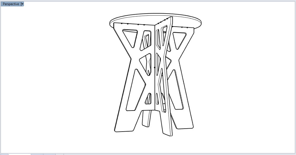 Coffee Table (Rhino)
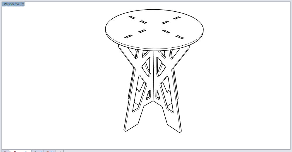 Coffee Table (Rhino)
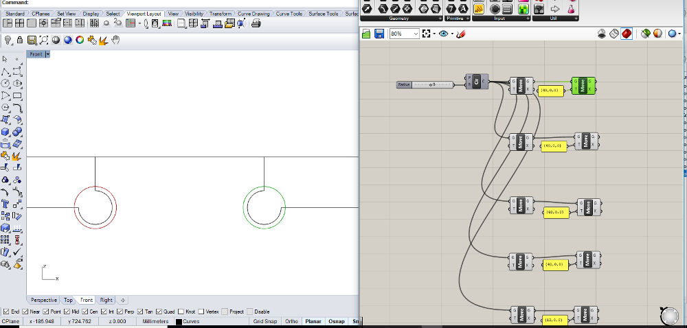 Changing the radius in Grasshopper
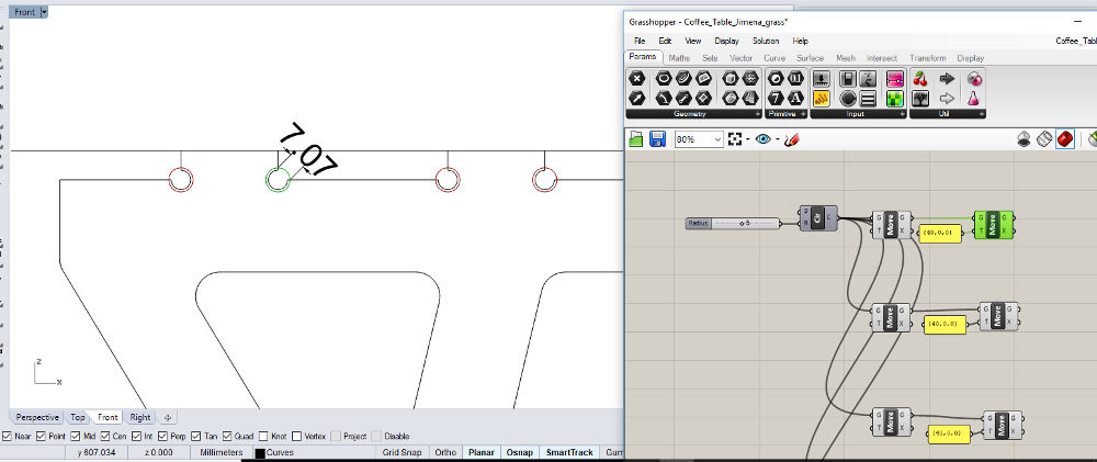 Changing the radius in Grasshopper
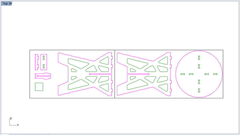 Pieces on the wood sheet
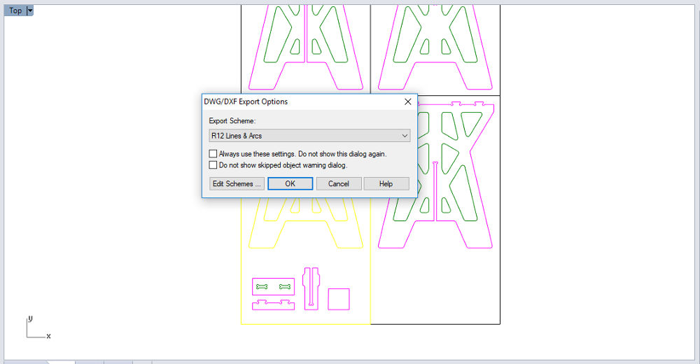 Export DXF
MILLING SOMETHING BIG
SAFETY RULES
- Keep the work bench clean. Check it
before you start.
- Don’t reach into a powered tool.
- Wear safety glasses and ear noise protection.
- Wear good shoes, so you don’t hurt your feet.
- Your clothes can have anything lose. Don’t wear jewelry.
- Your hair has to be tight back.
- The chips and toll can break and fly off. They are sharp and hot, be careful.
- Before you turn the machine on, you have to know how to turn it OFF.
- Before you start cutting the plywood, start an air cut first. You can see if the toolpath is right.
- Be concentrated and take time for this assignment.
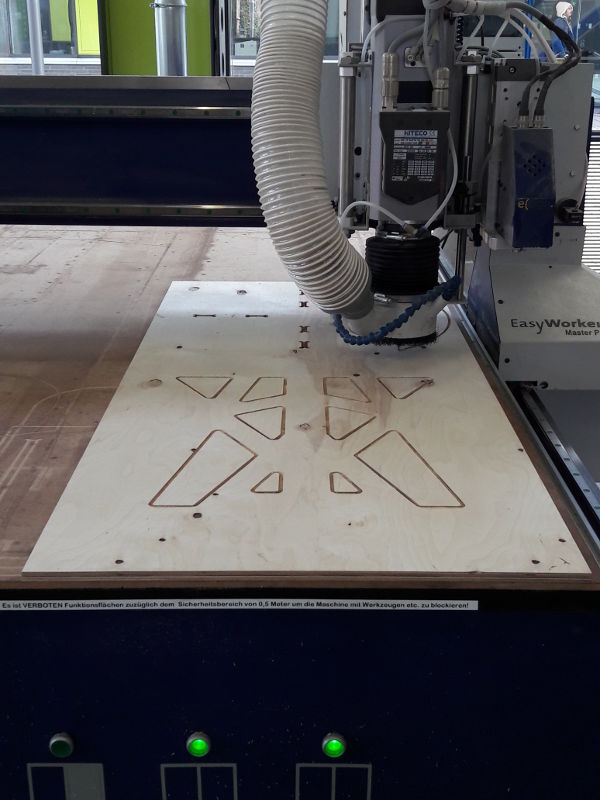
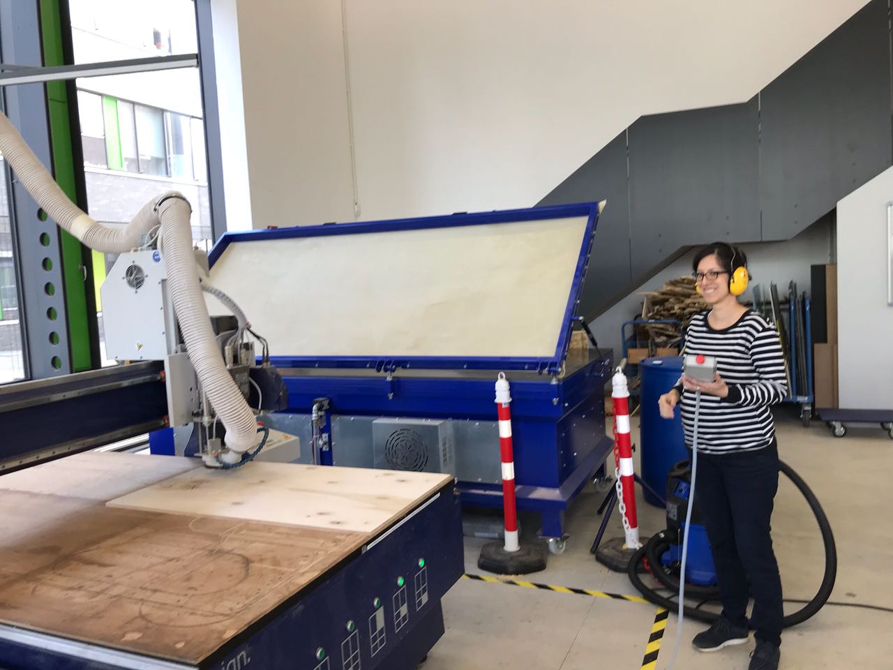
USING THE CNC MACHINE
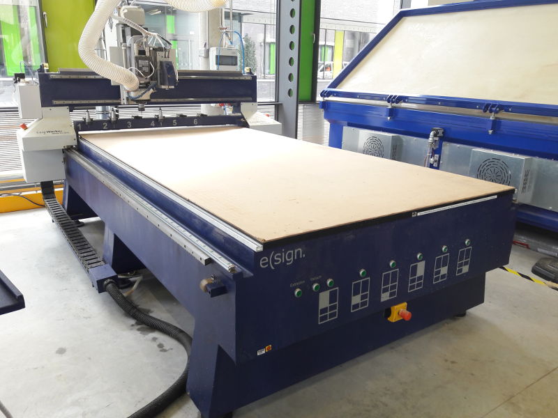
For this assignment we are in the
Fab Lab Kamp-Lintfort to use the CNC machine elsign EasyWorker Master pro 2513. The instructor of Kamp-Lintfort Daniele Ingrassia explains us, how to use the CNC machine.
- We start checking the safety rules and clean up the machine bed.
- The CNC machine has a control station (PC, monitor, keyboard, mouse), a controller (placed on the side of the control station) and a vacuum table.
The working area is 2600×1400×300 mm.
- The sacrifice material is an MDF sheet. We have to change it because it was uneven and the wood sheet doesn't lay entirely.
- After placing the material, we align it and switched on the vacuum table. We examine if the wood sheet lays even. If it’s necessary we use the hammer or press it manually. If that doesn't work, we turn over the wood sheet.
Note: for my project it is not important which side of the wood sheet is upside because the design is symmetric. Some wood sheets have a “good” and a “bad” side.
- On the front side of the CNC machine you can see if the vacuum table is activated. Green light buttons show, which area is on or off.
- We open the software and start with the settings.
- To use the controller you have to press the button on the side simultaneously. If you additionally press Shift, it would move faster.
For fine-tuning use the button Jog.
- The next step is to home the X and Y axis with the controller with the the button ZERO X/Y. The software shows now X:0.00, Y:0.00.
- To home the Z axis we use the height sensor. We take it and place it on the sacrifice material, then move the milling head above the sensor. Then select automatic calibration on the software. The mill head will move very slowly till it press the sensor with the end-mill. This setting will be saved for the next jobs.
- On the software (Program) I load the first DXF file “Tests” and set the DXF Origin -LL- (Lower Left). All the layer in your DXF file are visible.
- Then I deselect the layers I don't want to mill. Normally you start with the inlines. I also uncheck the layer for the wood sheet.
- The settings depend on the diameter of the end-mill and the material. I am using a laminated wood sheet with a thickness of 12 mm.
SETTINGS: OFFSET / CUT OUT
→ Safe-Z: 20
→ Start-Z: 13 (12 mm laminated wood sheet + 1 mm)
→ Final-Z: -0.1 mm (so are you sure that the material will be cut trough)
→ Z Increment: 3.5 (it depends on the material thickness, the mill head drives each path four times)
→ FeedRate: 1500
→ PlungeRate: 800
→ SpindleRate 18000.000
→ SpindleDirection CW (clockwise)
→ ToolNumber: 3
→ ToolDiameter: 6.000 (mm)
→ Method: Inside CW (for Inlines) or Outside CW (for Outlines)
- The next step is to calculate the toolpath → press the button (now you see the toolpath on the screen). Finally, save the G-Code.
- Start the air filter machine.
- Go to 'Operate' on the software and click on START
DUST COLLECTOR
During the milling process we change the height of the dust collector:
- Go to 'Operate' and click on 'Stop'.
- Click F7 Dust Cover and change the height.
- When you are ready you start the spindle again and continue the job.
 CNC machine elsign
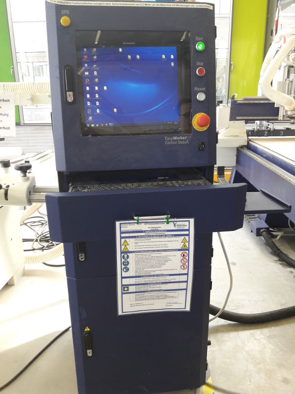 Control Station
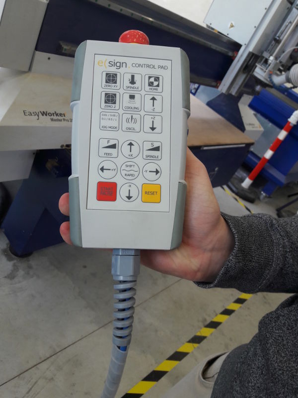 Controller
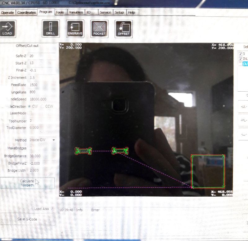 Program: Settings and Toolpath
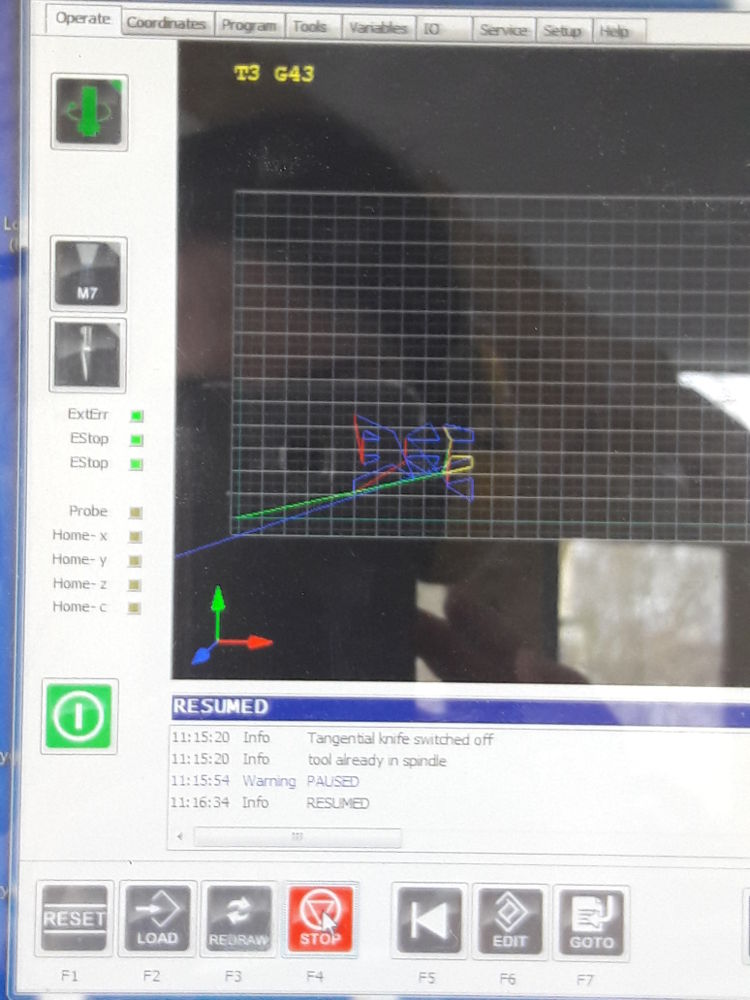 Toolpath
 .
. .
.CHANGE THE WOOD SHEET
Here I describe the steps:
If the milling machine has finished a job:
- Stop the vacuum table.
- Drive the milling head higher in the Z axis and then to the back (outside the wood sheet).
- Take the wood pieces of the machine bed and clean them with a vacuum cleaner.
- Place the new wood sheet on the machine bed, align it. If the material and the wood thickness hasn’t changed you can use the same setting on the software.
- Check if the filter is on and start the vacuum table.
- Drive the milling head to the start corner of the machine (LL). My design is placed almost at the edge of the wood sheet (distance 10 mm).
So I have to move the milling head so slowly, the axis of the end-mill had to be above of the wood sheet edge.
- Then I reduce the Z axis very slowly and home the XY axis with the controller. You don’t have to home the Z-axis again, the settings are already saved in the software.
- I load the next DXF file in the software, all the layer are checked and clicked on -LL-. After that you calculate the toolpath, you save the G-Code.
- Then you change the view of the software to 'Operate'. If everything is fine, you start the job.
- When the machine starts milling you have to stay near the machine with the controller in the hand and check that everything is working fine. If there is a problem, press the red button on the controller.
- When the job is finished, we clean up with an industrial vacuum cleaner.
 Setting the Z axis with the sensor
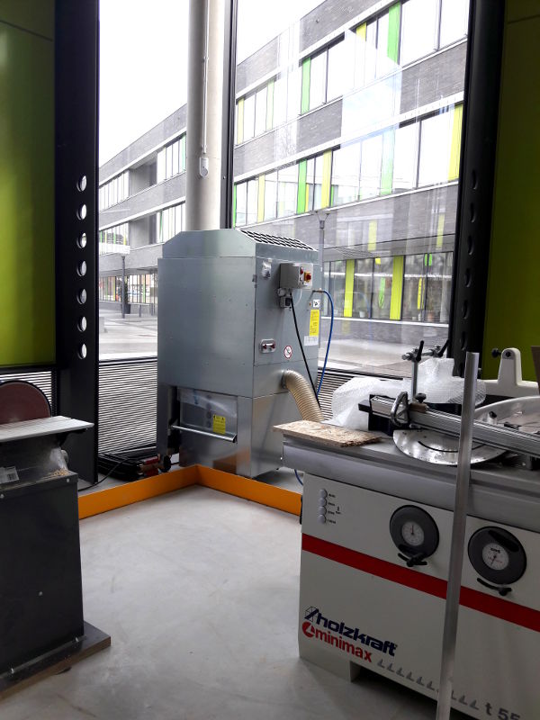 Filter
GROUP ASSIGNMENT: TESTS
KERF
I test the kerf width for the end-mill we are using (diameter 6 mm) and mill a 100×100 mm square as an inline. The software calculates the offset depending on the diameter of the end-mill you are using.
The CNC cuts a 99.50 mm square with round corners, because I choose 'Inline-Offset'. The size of the square is 87.73x 87.73 mm.
You can choose the offset for inlines or outlines.
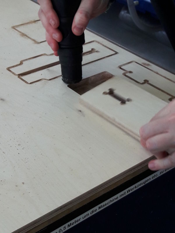
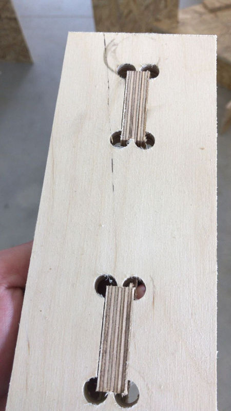
T-BONE JOINTS
I also test the t-bones joints for the coffee table. I use a laminated wood sheet with a thickness of 12 mm.
For the 6 mm end-mill I change the radius of the t-bone joints from 4 mm to 5 mm. The radius can’t be smaller than R=5 mm otherwise the CNC cannot mill the pockets of the joints.
 Tests
Tests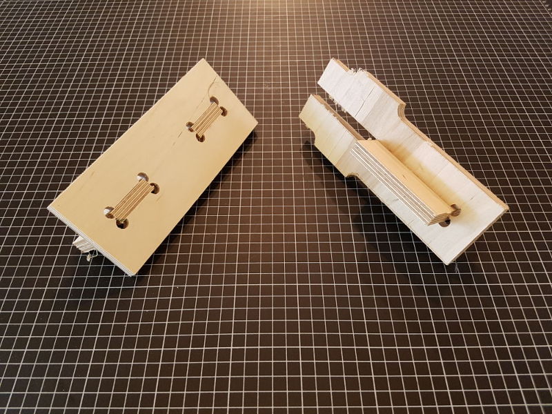 Tests
Tests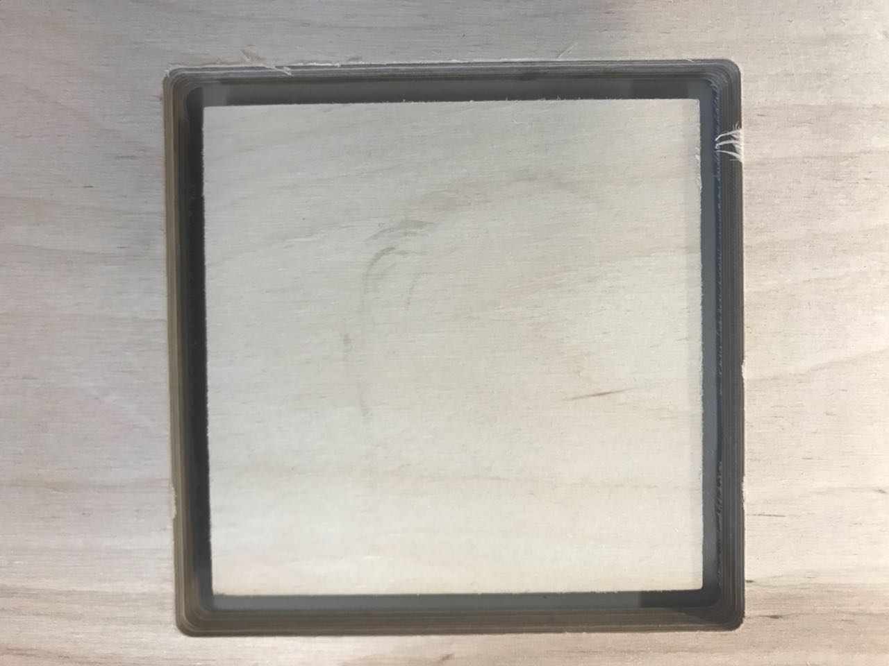 Tests
Tests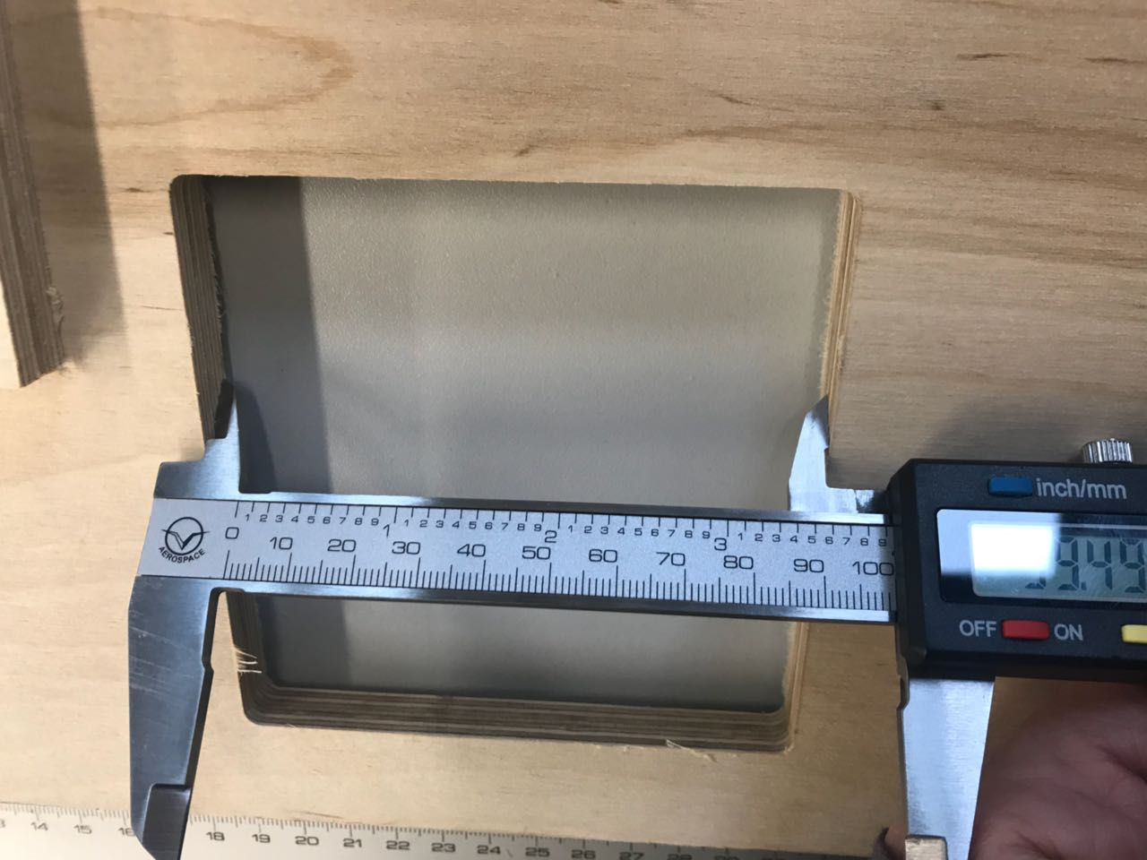 Tests
Tests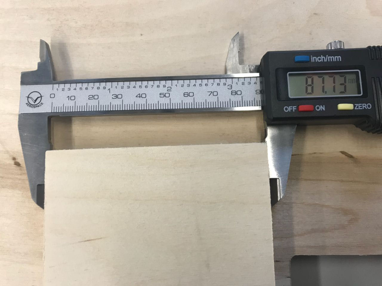 Tests
TestsMILLING | ASSEMBLING SOMETHING BIG
- The first thing I do is to check
the tests. The joints fit very well, so I don't have to change the joints in my design.
- After the tests, we mill the 3 big pieces for the coffee table. I describe the milling process above.
The three pieces fit together without problems. Finally, I sand the edges and assembled the coffee table. I’m very happy with the result!
Thank you very much to the Fab Lab Kamp-Lintfort and Daniele Ingrassia for the support!
 FabLab Kamp-Lintfort
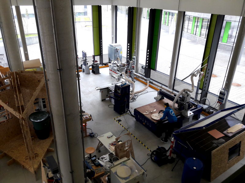 FabLab Kamp-Lintfort
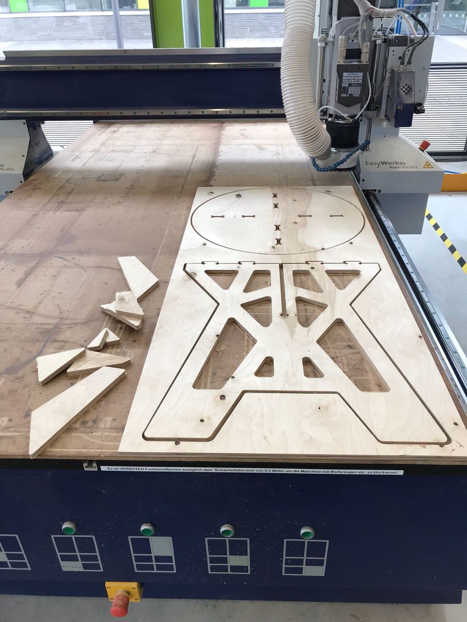 Milling the Coffee Table
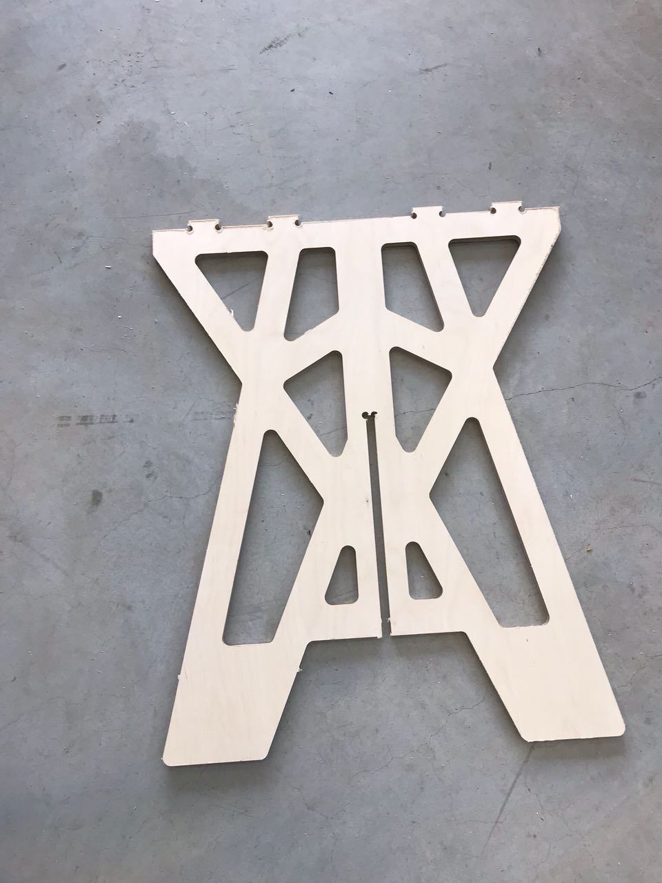 Coffee Table
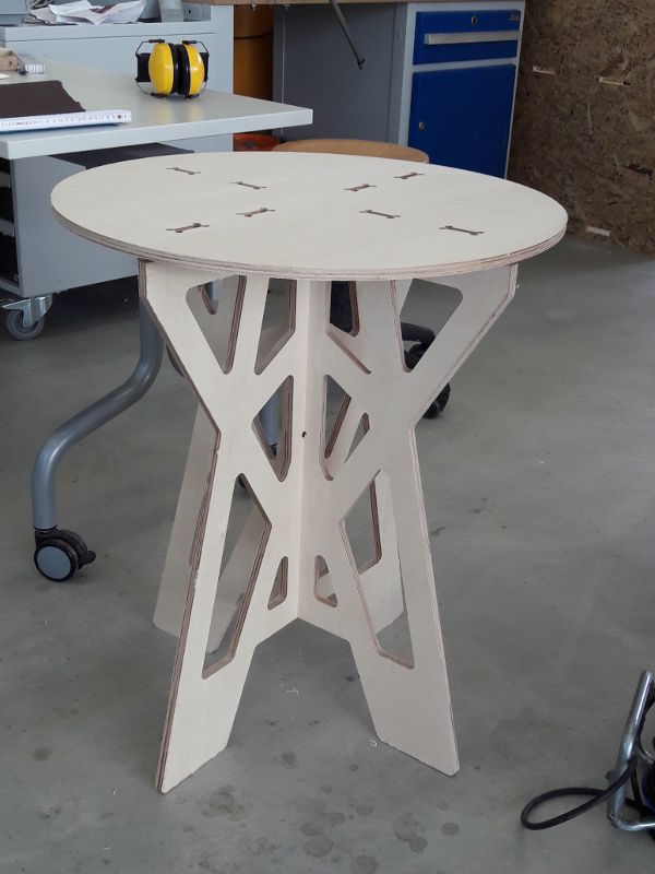 Coffee Table
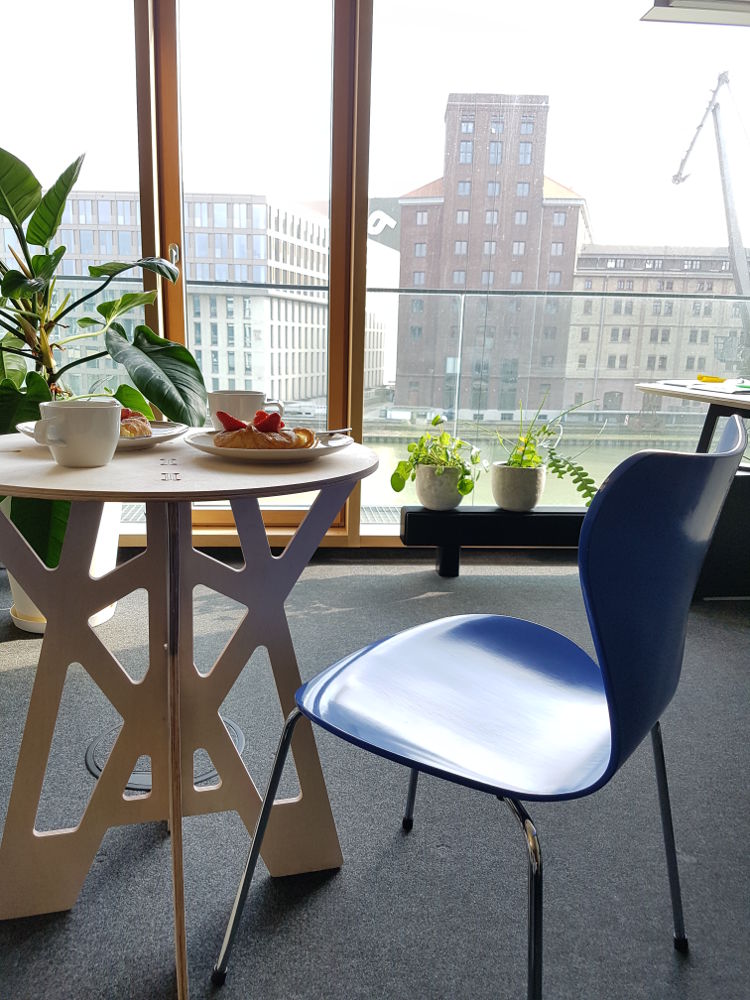 Coffee Time
Download
| Rhino and Grasshopper files(zip) | Download |
| DXF Export files(zip) | Download |