
Task:
INDIVIDUAL assignment
- measure something: add a sensor to a microcontroller board that you have designed and read it
GROUP assignment:
- measure the analog levels and digital signals in an input device
Measure the analog levels and digital signals in an input device
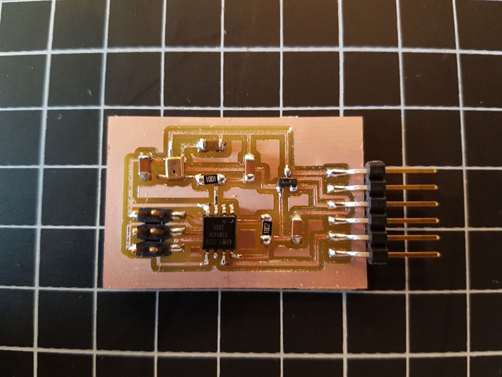
DESIGNING A MICROCONTROLLER BOARD WITH A SENSOR
I want to test the MEMS sound sensor, because I am thinking about integrating it into my final project. For example, the sensor could record audio, if the 'emergency station' is triggered. More about this in my final project page.
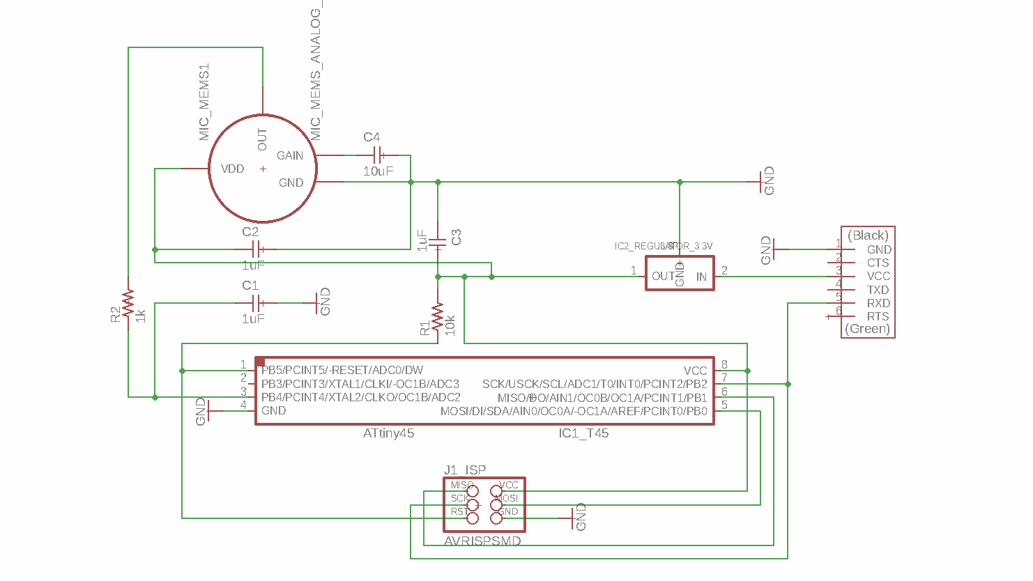
EAGLE: Schematic:
First, in Eagle, I add the required components from the Fab library. Then I use the 'Net' command to connect the components. For the schematic design, I use Neil’s template for the sound sensor as a reference.
Electrical Rule Check (ERC): it shows me an error that I could not fix. I compare the template with my design and find no difference.
EAGLE: Board Layout:
I move the components to the right place and connect them with the 'Route' command.
Design Rule Check (DRC): after moving some traces where the Clearance (spacing) is not enough, I export the board layout as an image file (png, 1200 dpi, monochrome).
GIMP:
In Gimp, I invert the color, added the outline, layer and export two PNG files 'Traces' and 'Outline' for the fabmodules.
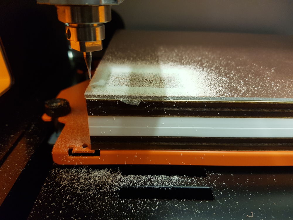
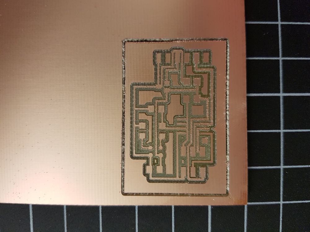
FABMODULES and Milling with Roland SMR-20:
You can see the settings for exporting the .RML files in the screenshots.
Note: I still have a problem with the RML file for the outline. The CNC machine is not milling through the hole thickness of the PCB material. I need to check the settings. I have to cut the board with a knife.
I describe in more detail how I work with Eagle (Commands, Schematic and Board Design, ERC and DRC, Export Settings), Gimp and the Fab Modules in the assignment Electronics Design.
In the download section you can find the Eagle, image (PNG) and CNC (RML files.
 Schematic
 Schematic ERC
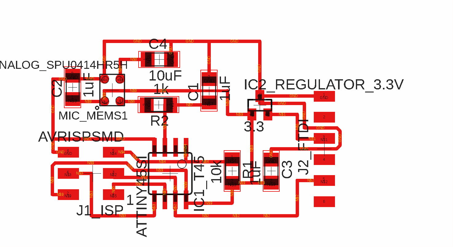 Board Layout
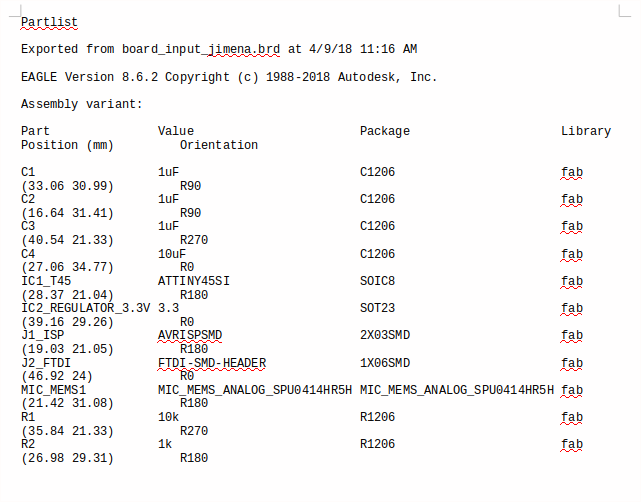 Board Layout export partlist
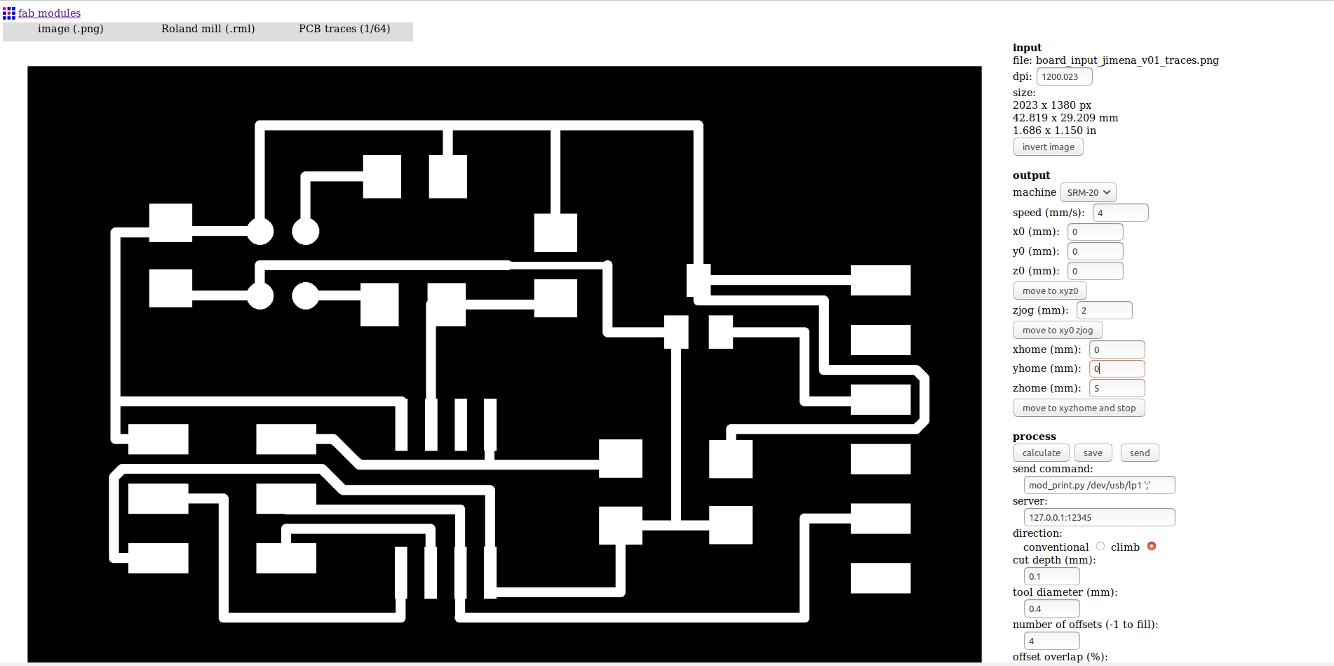 Fabmodules png file
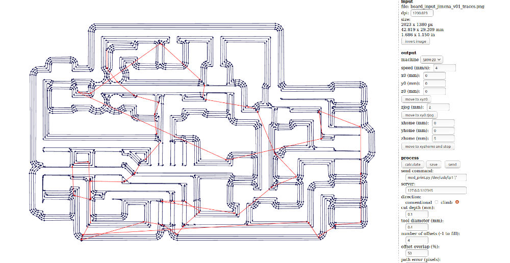 Fabmodules calculates G-Code
READING THE MEMS SOUND SENSOR
MEMS: microelectro-mechanical systems technology
Before I start programming, I want to understand the difference between MEMS microphones and Electret Condenser Microphones (ECMs) and find these pages helpful:
MEMS microphone Basic Principles
DATA SHEET, MEMS SOUND SENSOR Knowles SPU0414HR5H
Amplified Ultra-Mini SiSonicTM Microphone Specification
With MaxRF Protection - Halogen Free – Analog - Solder Pads Knowles Acoustics
Application: Electronics products including smart phones, feature phones, entry phones, laptops, tablet PCs, netbooks, PDAs.
Operating Temperature Range: 40 C to +100 C
Storage Temperature Range: -40 C to +100 C
Directivity Omni-directional
Current Consumption Across 1.5 to 3.6 volts, Limits 350 µA
Supply Voltage: Min. 1.5V – Max 3.6V
Typical Free Field Response: 100Hz ~ 10kHz
Mechanical Specifications: Illustration from the data sheet:
Dimensions in millimeters
Do not pull a vacuum over port hole of the microphone.
Do not insert any object in port hole of device.
 Dimensions
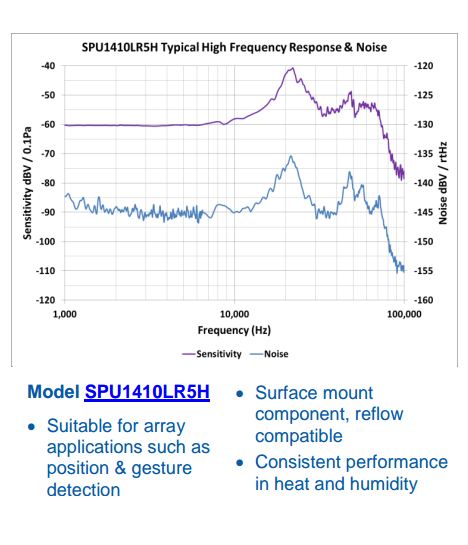
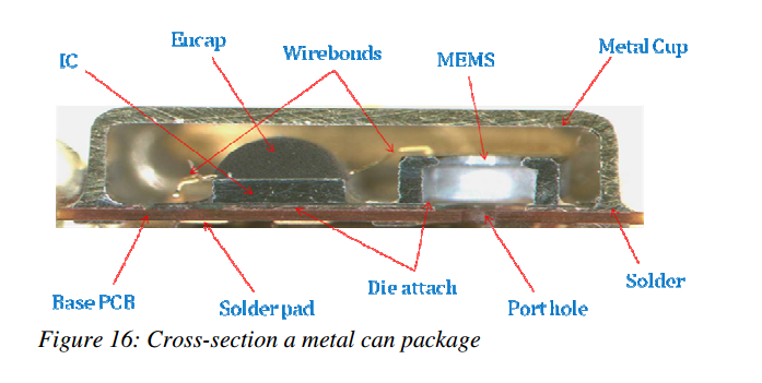 Cross-section
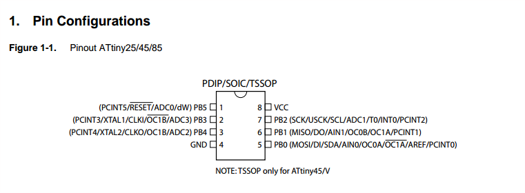
DATA SHEET ATtiny45
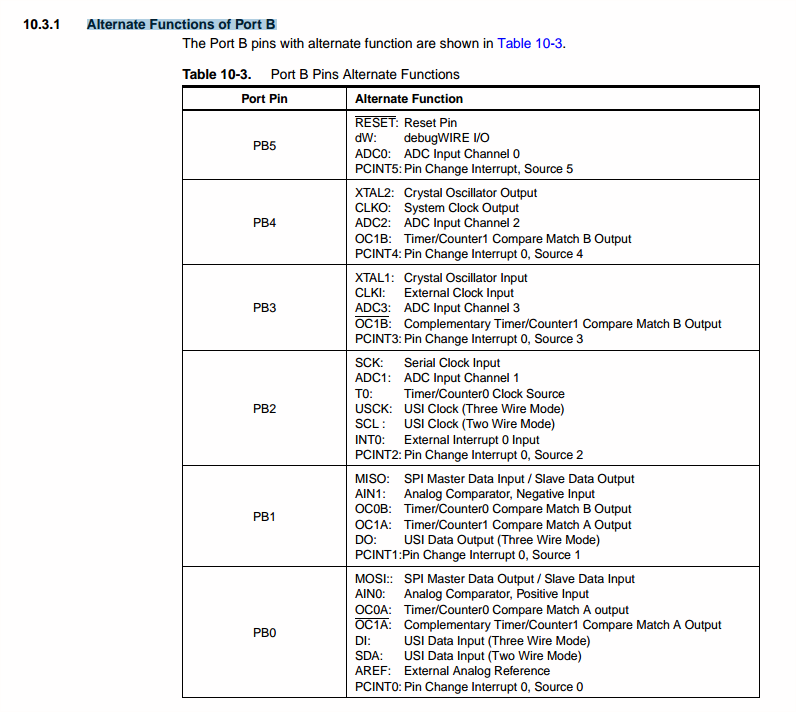
PIN CONFIGURATION (page 2) The ATtiny45 has 8 pins. See the schema:
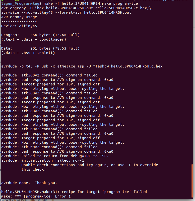
PROGRAMMING in UBUNTU
In the Ubuntu terminal, go to the folder where you save the make file:
→ cd …… (folder name)
Now enter this command:
→ $ make -f hello.SPU0414HR5H.make
These files are created in the same folder:
hello.SPU0414HR5H.c.hex and hello.SPU0414HR5H.out
Note: Programming with Ubuntu does not work. The programmer Atmel ICE is not recognized/read.
PROGRAMMING in WINDOWS → with ATMEL STUDIO
FIRST TRY
Atmel Studio is the integrated development platform (IDP) for developing and debugging all AVR and SAM microcontroller applications. It is an
easy-to-use environment to write, build and debug your applications written for example in C code. It also connects seamlessly to the debuggers, programmers and development kits that support AVR and SAM devices.
You can install Atmel Studio on Windows only.
I have not worked with Atmel Studio jet, so I watch this tutorial.
Pololu: programming AVRs using Atmel Studio
Here I describe the steps I take to run the code in Atmel Studio 7 (AS7) :
- Open AS7 and create a new project
- Then select 'GCC C Executable Project C/C++', enter the project name, location and solution name.
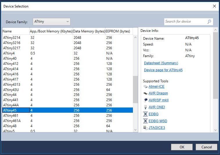
- Now select the device family → Attiny and then the device ATtiny45 → OK
On the right side there is the datasheet and the supported tools.
- Open the C-file (template of the lecture) hello.SPU0414HR5H.c
- Click on 'Build Solution' to compile the C Code → Get message 'Build succeeded'.
- Go to the Tools > Device programming > Select the tool (programmer), device, interface and click on Apply and then Read.
- Go to 'Memories' and click on 'Program'.
Note:
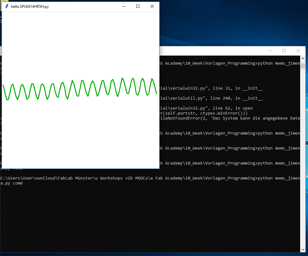
I can’t run the Python file from the lecture to detect the sound with the microphone.
My instructor Tobias told me to install Hterm to check if the serial port communication works. On the screenshot you can see that my computer receives data from the board.
The python file was still not running.
 Atmel Studio
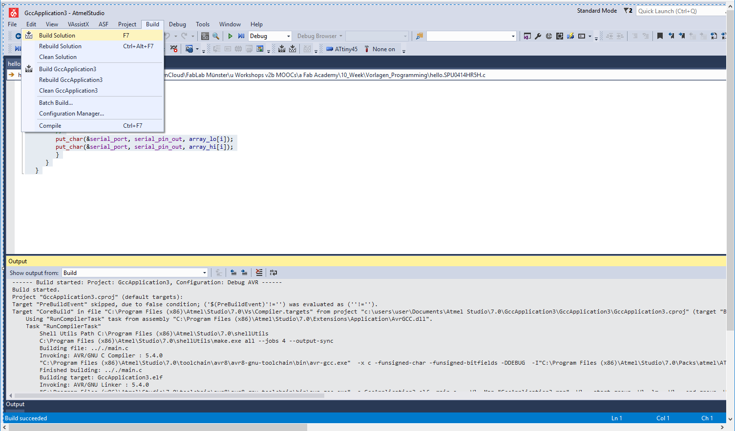 Atmel Studio
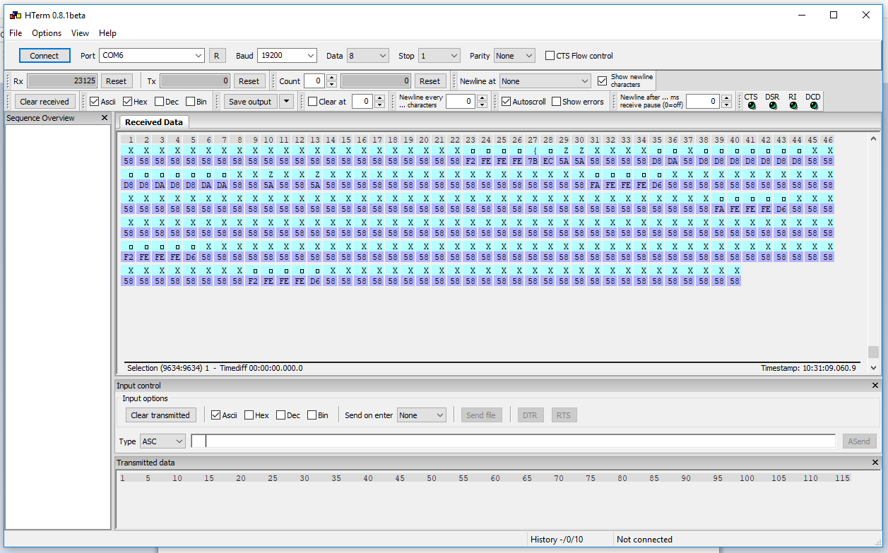 HTerm
HTerm Python
PROGRAMMING in WINDOWS → with ATMEL STUDIO
SECOND TRY
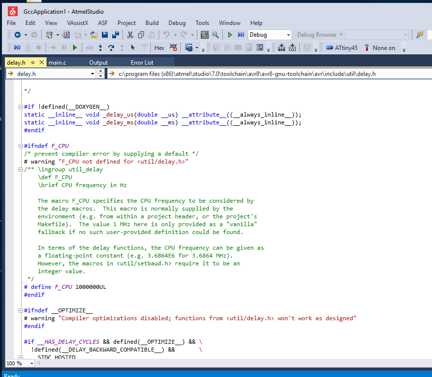
Back in Atmel Studio I test the 'Clean Solution' command and check the displayed error: 'F_CPU not defined...'
F_CPU: stands for the frequency of the CPU. It is necessary to define the value for functions like delay.h.
In this case the ATtiny45 uses the internal clock 8MHz:
So I add #define F_CPU 8000000 to the C code and select 'Build' to compile the code.
The next step is to check the settings in Tools > Device Programming:
You can see the settings I use in the screenshots.
My instructor Tobias tells me to check the settings in
Tools>Device Programming>Fuses and to compare them with the settings on this page:
Under Tools>Device Programming>Memories I select Program.
If there are no problems, the board is ready to detect the sound with the Python file.
 Atmel Studio
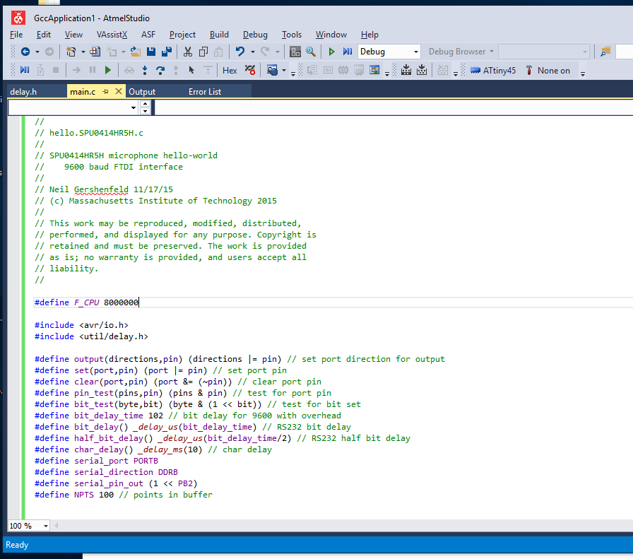 Atmel Studio
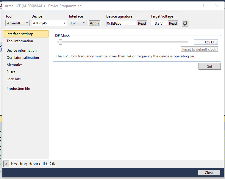 Atmel Studio
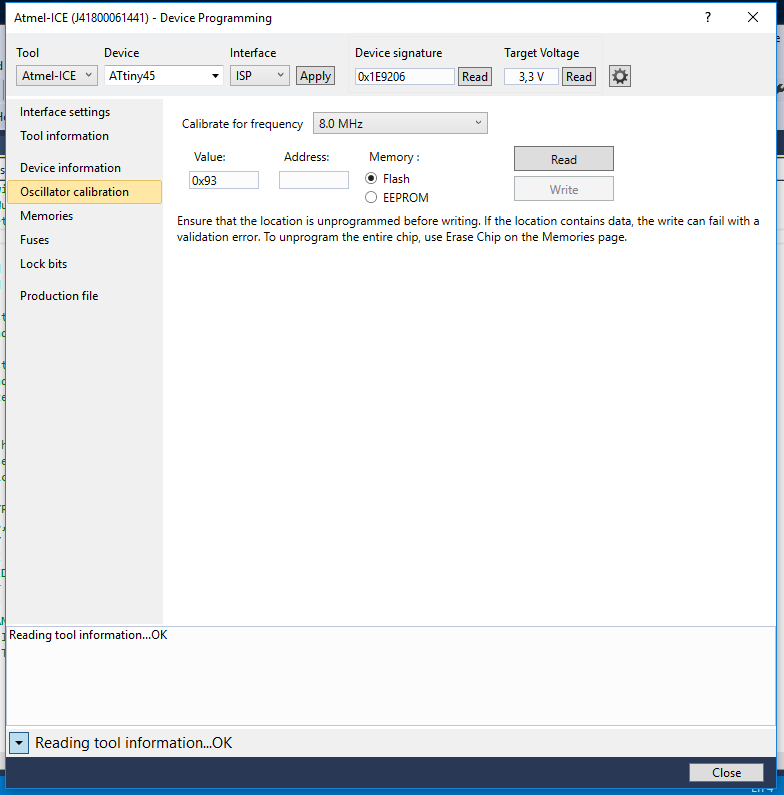 Atmel Studio
 Atmel Studio
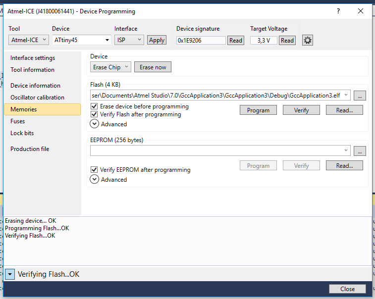 Atmel Studio
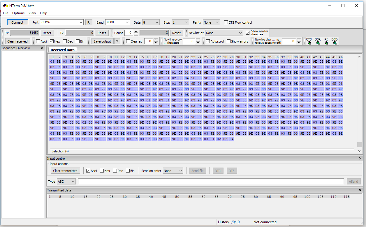 HTerm
HTerm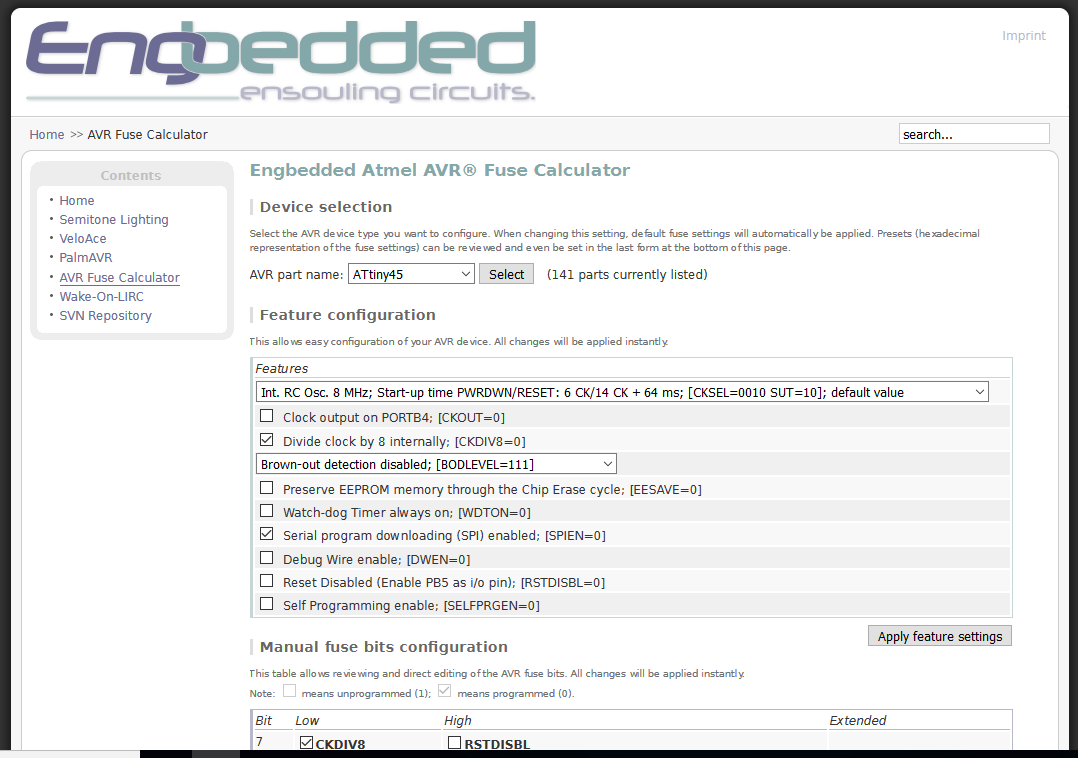 Engbedded
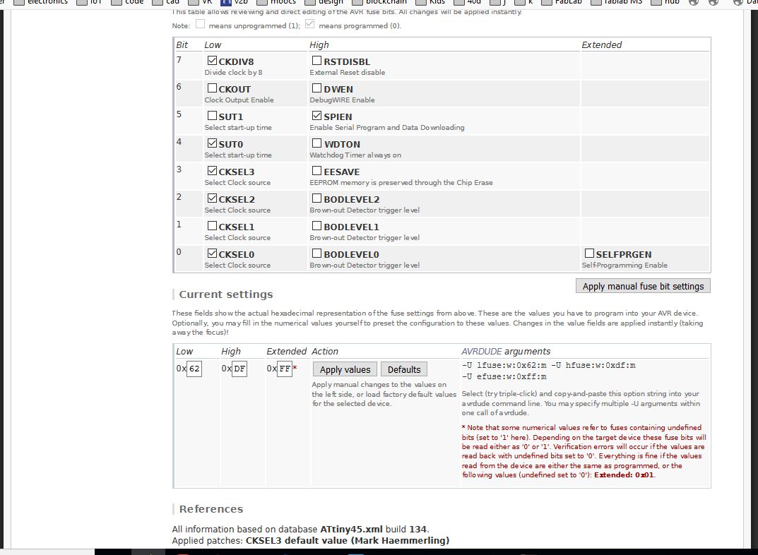 Engbedded
PROGRAMMING in WINDOWS → PYTHON
In the Windows terminal I open the Python file:
>python mems_jimena.py cpm6 and the interface opens. The mems microphone can detect sound!
Note: Windows is running the lastest version of Python. I check for errors with PyCharm and changed two lines of the code:
→ Version 2.7 → Version 3.6
→ from Tkinter import * → from tkinter import *
→ print "command line: hello.SPU0414HR5H.py serial_port" → print ("command line: hello.SPU0414HR5H.py serial_port")
 Detecting sound
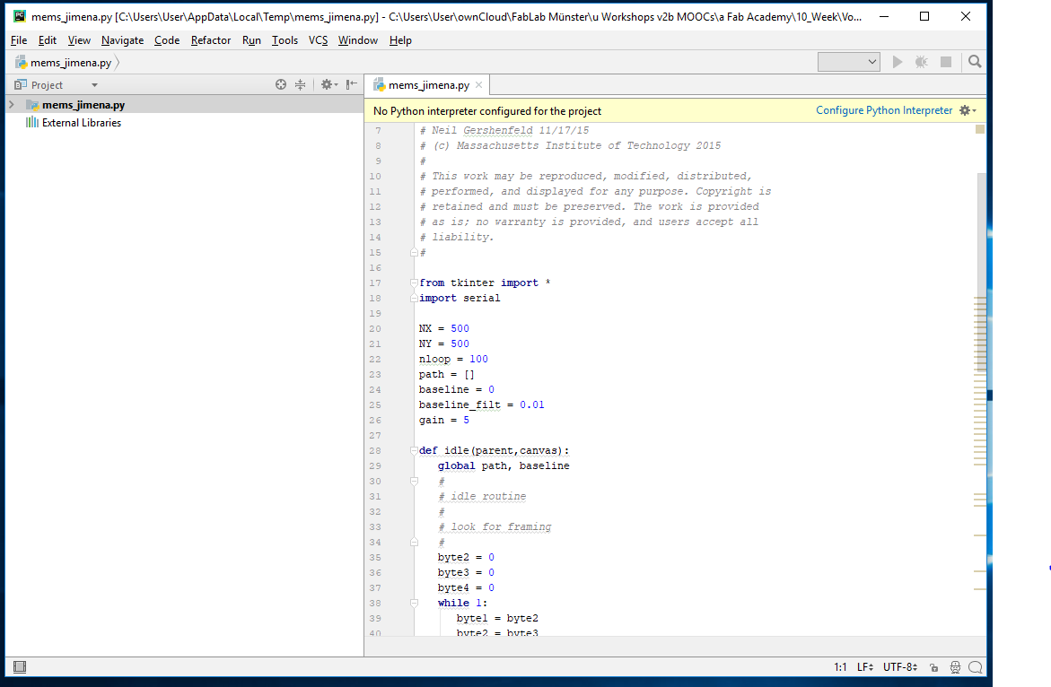 Changing the code
 Tkinter
SUPPLEMENT
BACK TO UBUNTU → PYTHON
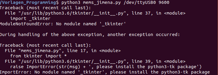
In order to run the lecture page python file hello.SPU0414HR5H, I need to install the tkinter and pyserial module for Python3. If you don’t have this module, you will see this error (screenshot).
To know which python version you have installed
→ $ python2 --version or
→ $ python3 --version
You can install the module the tkinter for python3 on Ubuntu by running:
→ $ sudo apt-get install python3-tk
The next step is to install the module serial for pyhton3
→ $ python3 -m pip install pyserial
NOTE 1: the Python templates from the lecture are written for pyhton 2.7.
You can run these programs by typing python2 instead python3 in the commands above.
NOTE 2: I change Neil’s template to Python version 3 by changing the code and renaming the file to mems_jimena.py:
→ Version 2.7 → Version 3.6
→ from Tkinter import * → from tkinter import *
→ print "command line: hello.SPU0414HR5H.py serial_port" → print ("command line: hello.SPU0414HR5H.py serial_port")
The terminal opens and I can see what the sensor is reading.
→ $ python3 mems_jimena.py /dev/ttyUSB0
ELECTREC MICROPHONE
In week Interface and Application Programming, I use an electrec microphone as an input device with Processing. See my documentation of the electrec microphone module:
 Installing module tkinter
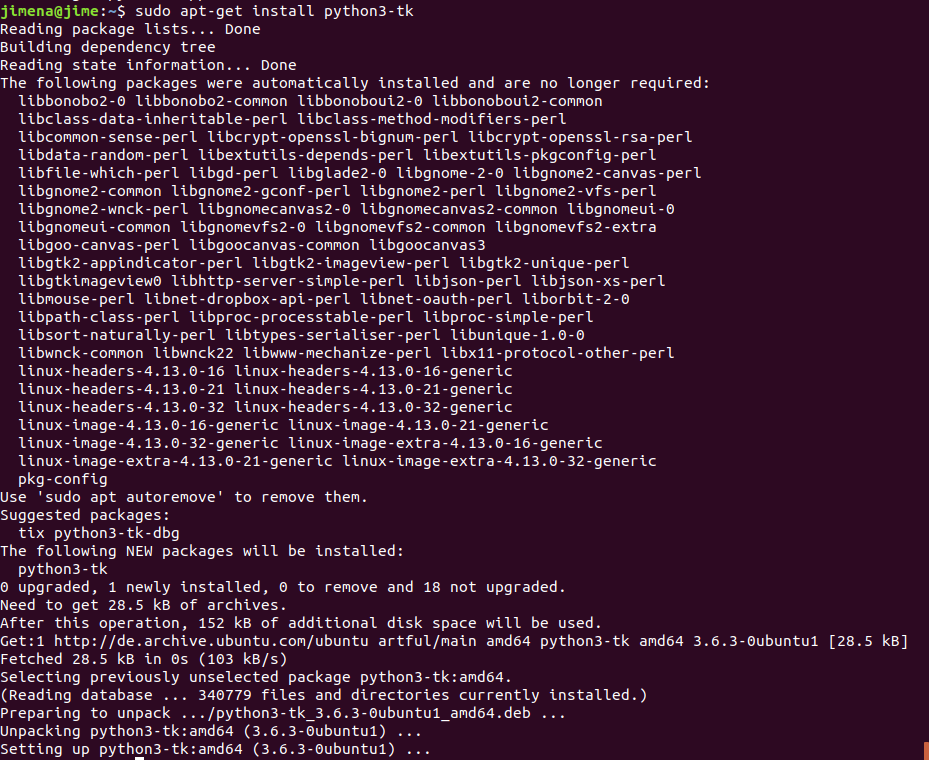 Installing module tkinter
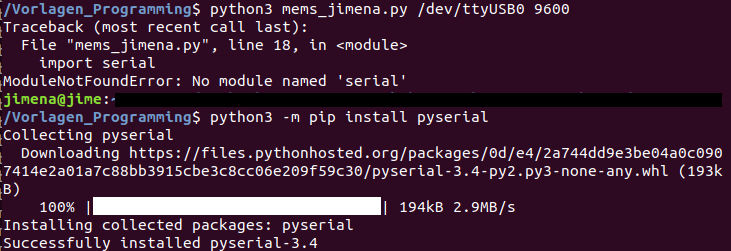 Installing module pyserial
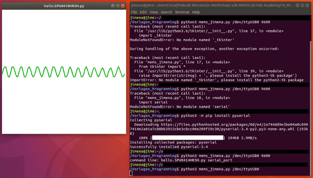 Running python file
UPDATE
About the code
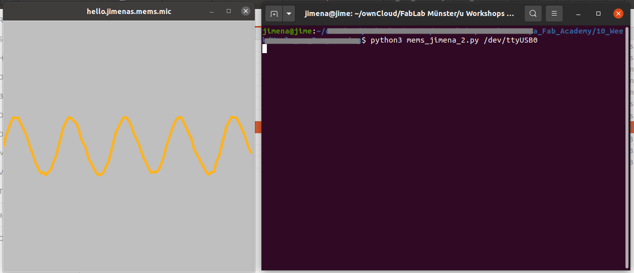
The program should visualize the reading of the microphone. For this purpose Tkinter is imported into the code. Tkinter allows you to create a graphical user interface (GUI).
It interacts with features, data, etc.
To test the code:
Open the terminal in the directory where the python file is located and type:
python3 mems_jimena_2.py /dev/ttyUSB0
(on windows e.g. COM3)
I have changed parts of the code and explained some functions. Have a look at the code below. You can also find the modified code in the download section.
 Testing the code
testing the modified code
#
# hello.SPU0414HR5H.py
#
# plot SPU0414HR5H microphone audio
#    hello.SPU0414HR5H.py serial_port
#
# Neil Gershenfeld 11/17/15
# (c) Massachusetts Institute of Technology 2015
#
# This work may be reproduced, modified, distributed,
# performed, and displayed for any purpose. Copyright is
# retained and must be preserved. The work is provided
# as is; no warranty is provided, and users accept all
# liability.
#	*1 modified by Jimena Gálvez 2021

from tkinter import *
import serial

NX = 500 							#*1   width of the window
NY = 500							#*1   height of the window
nloop = 100							# variables for the line
path = []
baseline = 0
baseline_filt = 0.01
gain = 5

def idle(parent,canvas):
   global path, baseline
   #
   # idle routine
   #
   # look for framing
   #
   byte2 = 0
   byte3 = 0
   byte4 = 0
   while 1:
      byte1 = byte2
      byte2 = byte3
      byte3 = byte4
      byte4 = ord(ser.read())
      if ((byte1 == 1) & (byte2 == 2) & (byte3 == 3) & (byte4 == 4)):
         break
   path = []
   for i in range(nloop):					# this part of the code creates the "wave"
      lo = ord(ser.read())
      hi = ord(ser.read())
      reading = 256*hi + lo
      baseline = baseline_filt*reading + (1-baseline_filt)*baseline
      value = NY/2 + gain*(reading - baseline)
      path.append(i*NY/float(nloop))
      path.append(value)
   canvas.delete("path")
   canvas.create_line(path,tag="path",width=5,fill="#ffb31c")	# line (wave) properties #+1 changed width 5px + color orange
   parent.after_idle(idle,parent,canvas)

#
# open serial port
#
ser = serial.Serial('/dev/ttyUSB0',9600)		          #*1 port namechanged e.g. '/dev/ttyUSB0' on Linux or 'COM3' on Windows
#
# start plotting
#
root = Tk()							# Initialize window, call constructor *1 changed library element
root.title('hello.jimenas.mems.mic')				#*1 changed title of the window
root.bind('Escape', 'exit')						#*1 handling1event: bind escape button to close GUI
canvas = Canvas(root, width=NX, height=NY, background='gray75')	# size of the window #*1 changed background
canvas.pack()							# function pack organizes the canvas
root.after(100,idle,root,canvas)		              # function after 100 miliseconds
root.mainloop()							#*1 Main loop. GUI doesn't disappear right away.
Download
| Eagle, Image and CAM files (zip) | Download |
| C-code and Python files (zip) | Download |
| New Python file (zip) | Download |