
Task:
INDIVIDUAL assignment
- write an application that interfaces with an input and/or output device that you made
GROUP assignment:
- compare as many tool options as possible
Compare as many tool options as possible
Write an application that interfaces with an input and/or output device that you made
For this week’s assignment, I decide to use an Electrec microphone and test it on a breadboard using the Arduino IDE.
ARDUINO IDE
For the first tests I build a breadboard layout and connect it to an Arduino UNO. I find this tutorial very helpful to get started:
Sketch 01, clap switch:
I modify the sketch and set some variables. You can find the Arduino sketch at the bottom of this page.
Sketch 02, detecting sound:
For the next step, I modify the sketch again. The LED should blink while the microphone detects a sound. You can find the sketch in the 'Load' section and the video in the 'Milling and Soldering' section on this page.
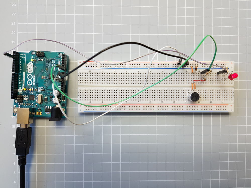 Breadboard Project for Arduino Sketch
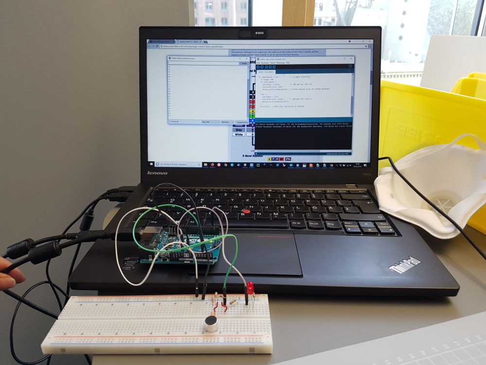 Test Arduino Sketch>
EAGLE
The sketches work as expected, so I start a Schematic drawing for a microphone module based on the tutorial mentioned before. You can find the schematic and the board layout in the download section.
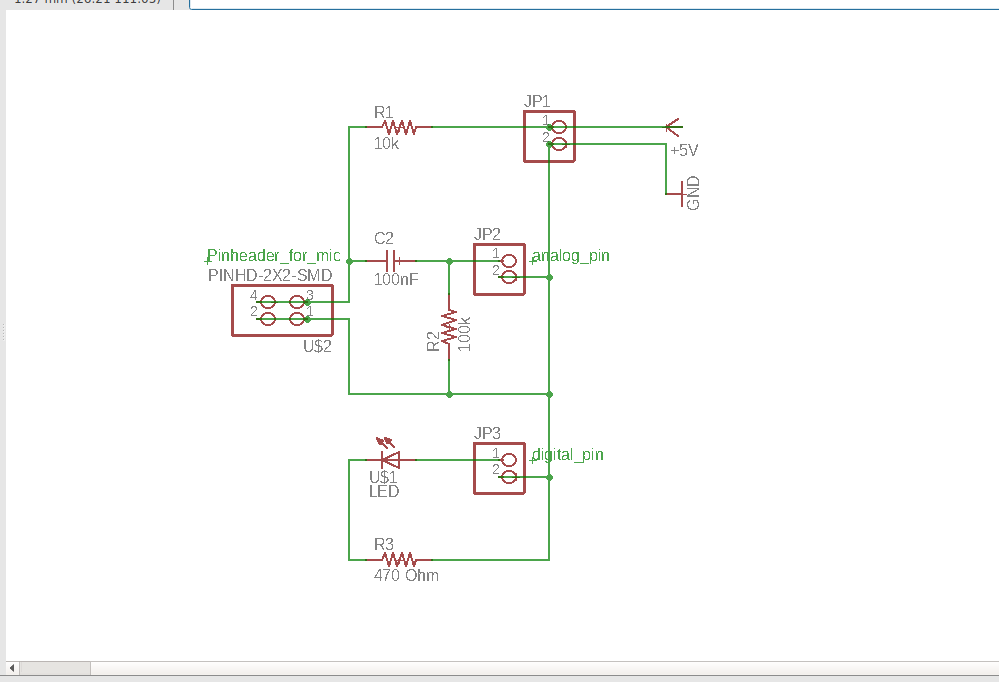 Eagle Schematic
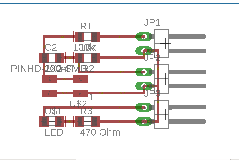 Eagle Board design
FABMODULES
To calculate the RML files I use the fabmodules.org page. You can see the settings I use in the screenshots on the right.
Note: Sometimes the CNC machine does not cut out the outline completely, so that I have to use a knife/box cutter.
So I change the default settings on the fabmodules for the outline:
- cut depth (mm): 0.65
- stock thickness (mm): 1.8
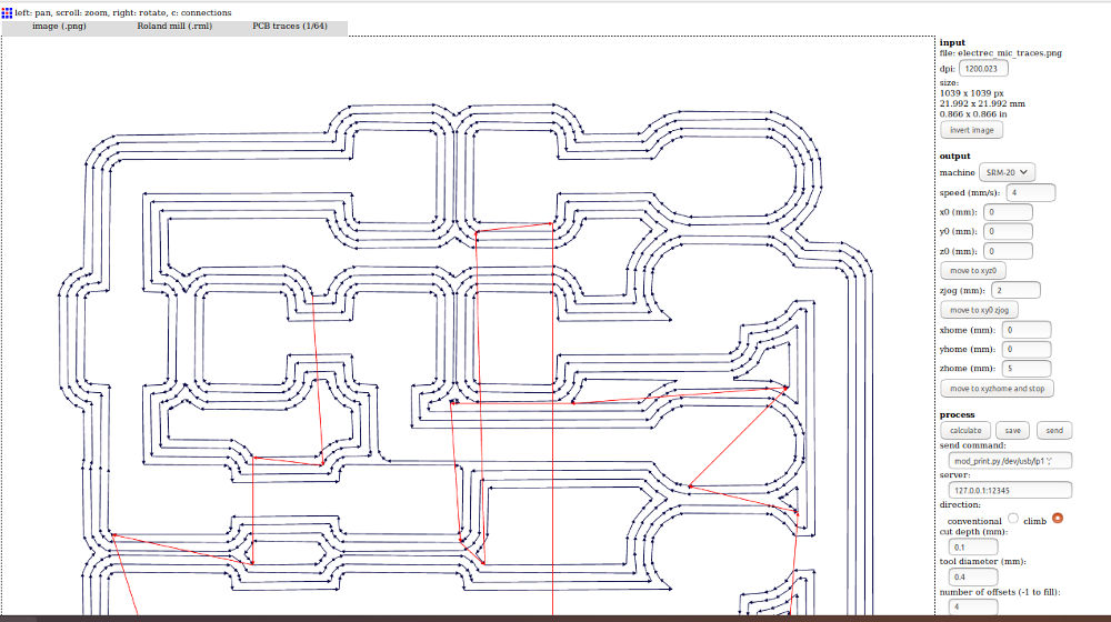 Fab modules traces
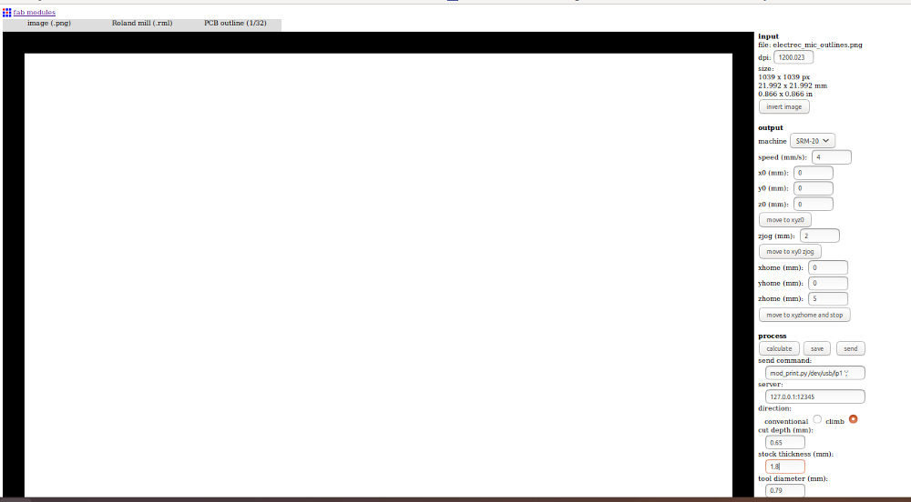 Fab modules outline
MILLING AND SOLDERING
The microphone module is very small (22 x 22 mm) and the milling process ends quickly. I put the components together and start soldering.
You can find the parts list in the download section.
To connect the microphone to the pin header, I use a 4-pin connector and a rainbow wire.
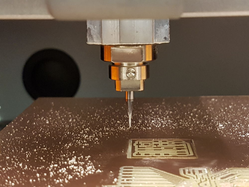 Milling the board
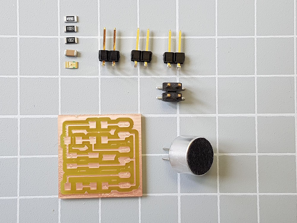 Components
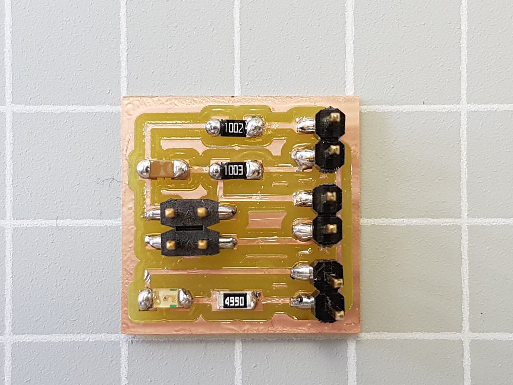 PCB is finished
PROCESSING
Processing is an open-source computer programming language with an integrated development environment designed for electronic arts, new media art and visual design. The programming language is built on Java. This project was initiated at the MIT Media Lab in 2001.
The first thing to do is to install the Processing software on Ubuntu.
- Download the latest version of the software to your home directory and open the terminal and type 3.3.7 for the latest stable version::
→ $ tar xvfz processing-3.3.7-linux64.tgz
- A new folder will be created, e.g. 'processing-3.3.7'
- For other versions replace the xxxx with the version number
→ $ tar xvfz processing-xxxx.tgz
- Now open the folder in the terminal: → $ cd processing-3.3.7
- And run the program with: → $ ./processig
The download files for Ubuntu, Windows and Mac can be found here:
STARTING WITH PROCESSING
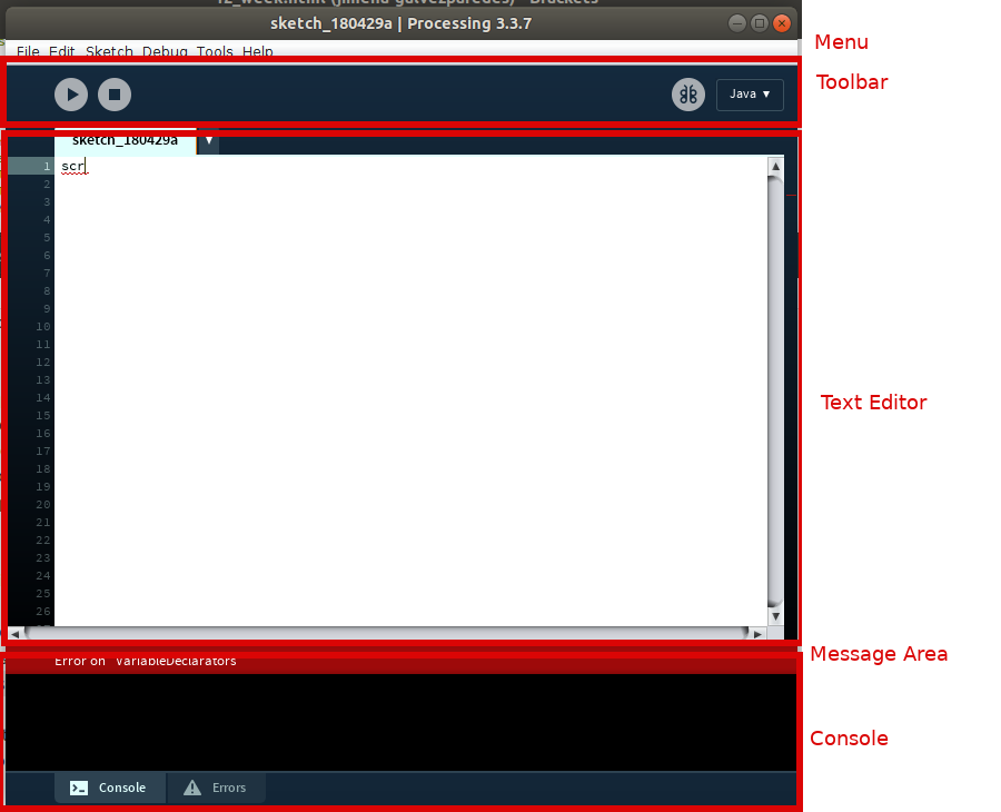
User interface
The Processing Development Environment (PDE) has a menu bar, toolbar, text editor, message area, console and a display window. See screenshot.
- Toolbar: there are three buttons: Run, Stop and Debugging.
Run compiles the code and opens the display window to run the sketch.
- Text editoris where you write your program, which is called sketch.
- Message Area is for one lne messages. It turns red when it detects an error.
- Console is for more information about technical details or errors.
- Display window appears when the sketch is running.
 Processing UI
Sketch
Sketches are saved in the sketchbook, which is a folder on your computer. There are two different types of sketches:
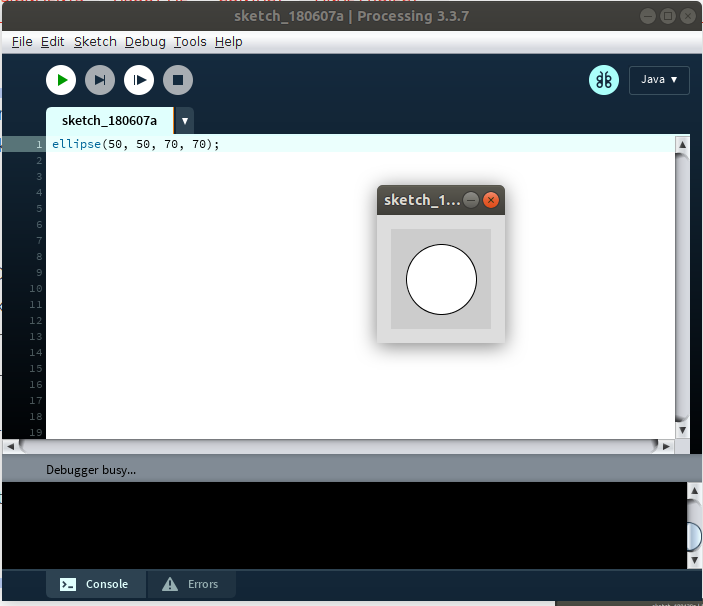
STATIC sketch:
creates a single image. For example:
ellipse(50, 50, 70, 70);
If you click on 'Run' the display window appears and shows a circle.
The center of the circle is 50 pixels to the left and 50 pixels down from the upper left corner of the display window. The height and width of the circle is 70 pixels. The origin is always the upper left corner of the display window.
INTERACTIVE sketch:
draws a series of frames, the image runs with animations or interactions.
You need the function setup(), which is executed once, and draw() block, which controls the animation.
Setup() | Window size:
In this part you can set the size of the display window. For example:
→size (600, 600);
A window with 600 pixels width and 600 pixels height will be created.
If you do not set the window size, the default window size is 100 x 100 pixels.
 Static Sketch
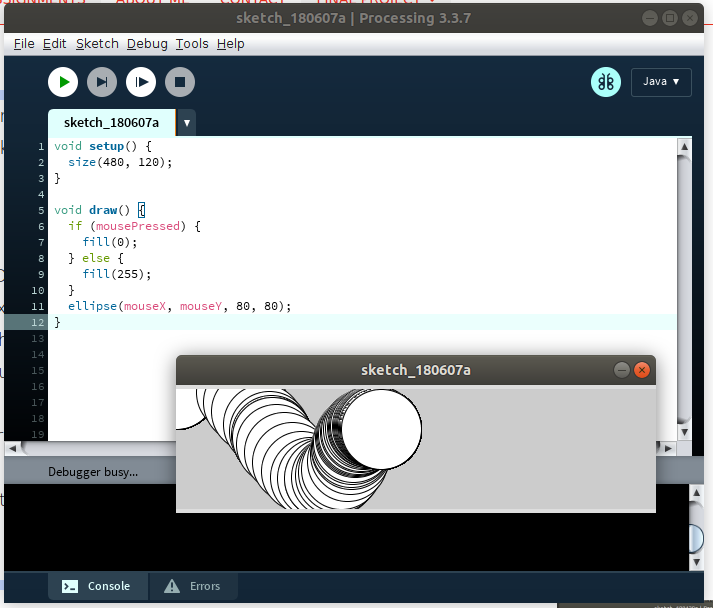 Interactive Sketch (@ processing.org)
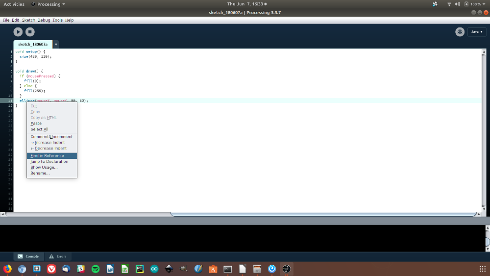
Functions | Processing Reference:
In the sketch, the functions have a different color (blue) from the rest of the code. If you right-click on the function and then select 'Find in Reference' a web browser window will open showing the explanation of the function.
Archive Sketch:
A very useful command is 'Archive Sketch' to save a
copy of your program as a .ZIP file. It is important to save different versions of your program so that you can revert to an earlier version.
More information about the menus in Processing
Here you can find more Processing tutorials
I start with a test sketch to understand some basics:
 Processing Reference
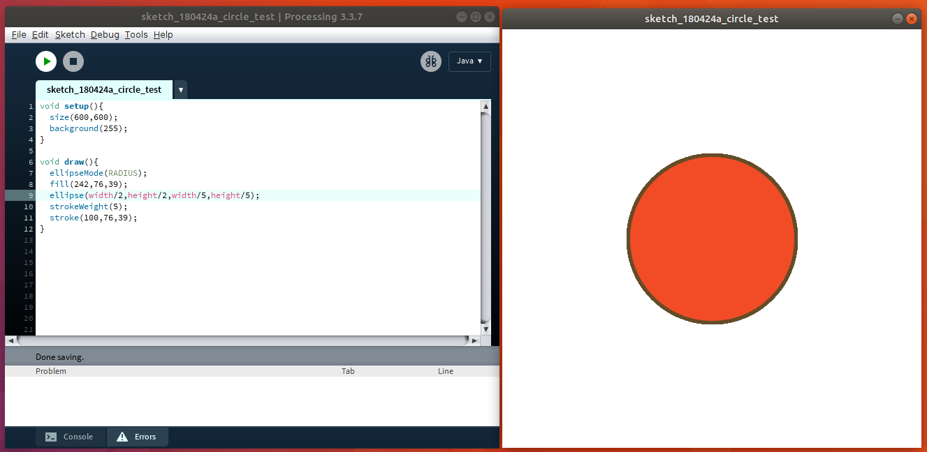
SKETCH 01: Drawing a circle with stroke.
Code is in the screenshot.
 Processing test
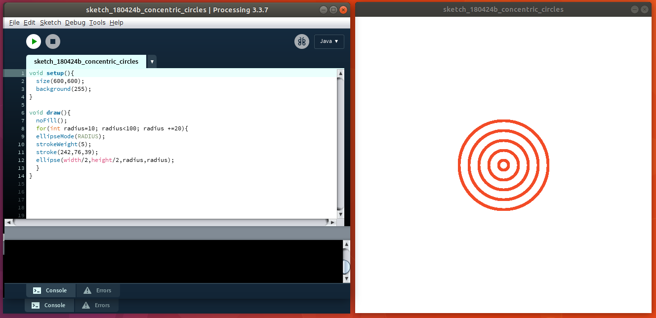
SKETCH 02: Drawing concentric circles.
Code is in the screenshot.
 Processing concentric circles
SKETCH 03: function readString()
I check the sketches of my instructors Aleksandra and Marcel to see how the serialEvent() and the serial library is used in the code.
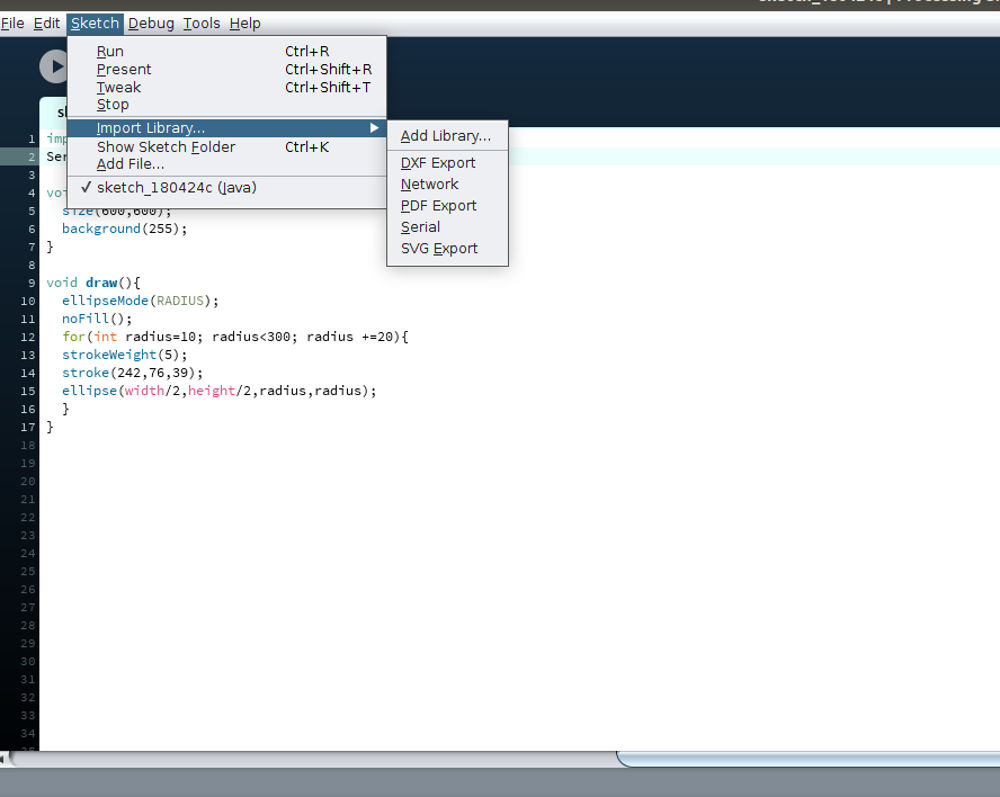
The library Serial must be imported in the sketch
> Menu Sketch > Import Library > Serial
The next step is to test the readString() function and test the reference program from the Processing website.
I am working with Ubuntu, the Arduino UNO is connected to port [0]:
“/dev/ttyACM1”. You may need to change the port number depending on the device you are using.
The setup() part lists all the available serial ports. The draw() part reads the values coming from the serial port. It works pretty well, so I can see the analog values in the message area.
 Processing Serial Library
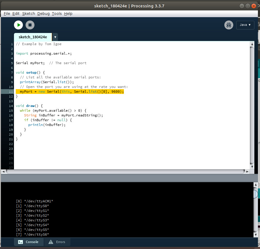 Processing readString
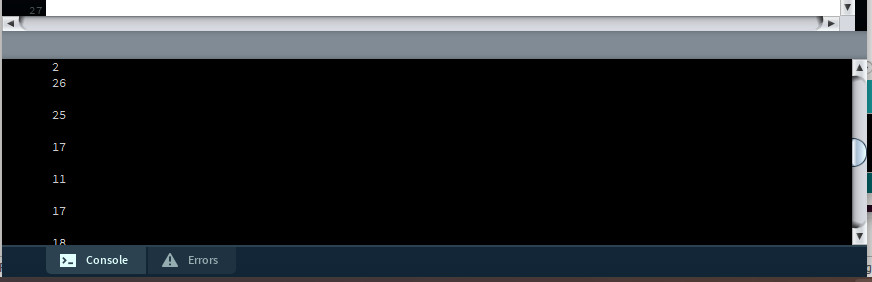 Processing readString
SKETCH 04: function serialEvent() | detecting sound
I test the function serialEvent(), which also works. Then I start adding new functions like ‘Ellipse’ to draw concentric circles when the sensor detects sound. Have a look at the video below.
Link to function serialEvent()
import processing.serial.*;

Serial myPort;    // The serial port

PFont font12;     // The display font
String inString;  // Input string from serial port
int lf = 10;      // ASCII linefeed

String Radius=inString;


void setup() {
  size(600,600);

  // You'll need to make this font with the Create Font Tool
  font12 = createFont("Helvetica", 13);
  // List all the available serial ports:
  printArray(Serial.list());
  // Open the port you are using at the rate you want:
  myPort = new Serial(this, Serial.list()[0], 9600);
  myPort.bufferUntil(lf);
}


void draw() {
  background(0);
  text("received: " + inString, 10,50);
  while (myPort.available() > 0) {

    String inBuffer = myPort.readString();
    if (inBuffer != null) {
      println(inBuffer);
    }
    noFill();

    ellipseMode(RADIUS);
    strokeWeight(5);
    stroke(242,76,39);
    ellipse(width/2,height/2,Radius,Radius);
    }
  }


void serialEvent(Serial myPort) {
  inString = myPort.readString();
}
Download
| Mic module: Eagle, image (png), CNC (rml) files and partlist(zip) | Download |
| Mic module: Arduino Sketches (zip) | Download |
| Mic module: Processing Sketches (zip) | Download |