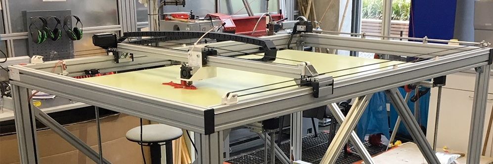
Big 3D-Printer
With a maximum volume of 150 x 90 x80 cm
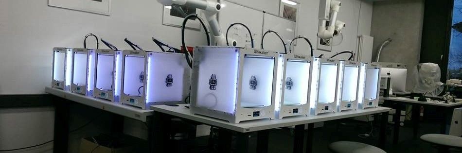
Some of our Ultimaker
We´ve got more than 25 3D-Printer of diffrent types
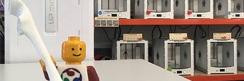
Greeting
Our best employee in HRW FabLab
Assignment 11:
Output devices
Task:
- measure the power consumption of an output device (group project)
- add an output device to a microcontroller board you've designed, and program it to do something
Work
This week we have to use an output device with our self-developed Board. Because my board of week 6 is able to handle this devices I don´t need to develop a new one. Cause I used a AtMega 328 controller– the same like for example a Arduino Pro – I´m able to use the Arduino IDE and also the output devices. So I could use all the Arduino libraries that makes it quite more easy to handle the devices. So I started with a servomotor.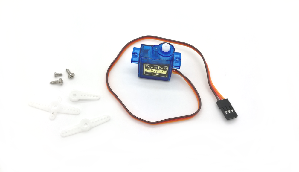
I used the standard Arduino servomotor TowerPro SG90 micro. I didn´t find a very good datasheet so find the best I got below under downloads. The servo has got only three connection pins. GND (brown), VCC (red) and one signal pin (yellow/orange).
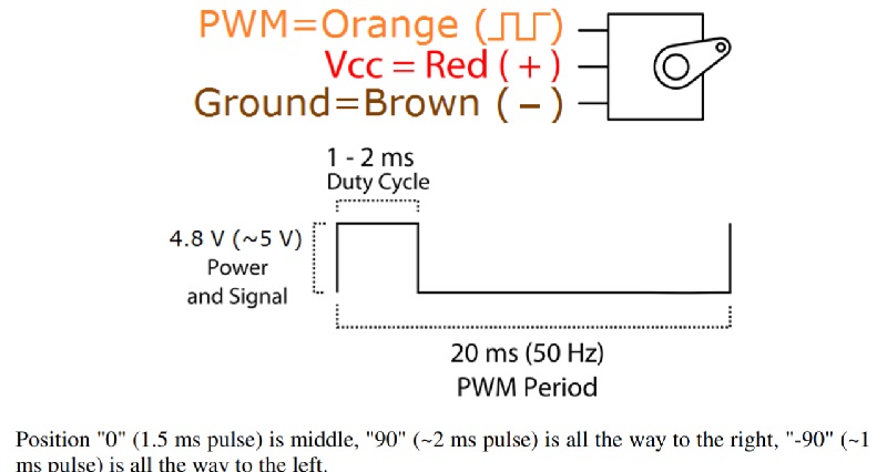
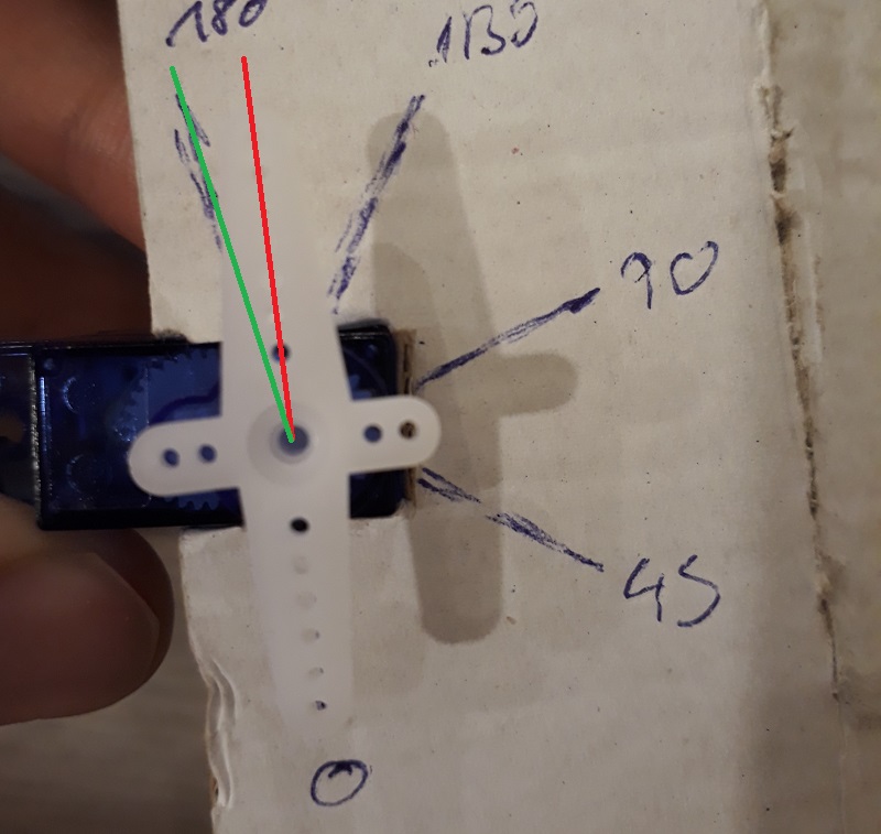
As you see the Servos uses the PWM - Pulse-Width-Modulation to controll the position of it. The Servo works with a frequenz of 50 Hz witch means, that one complete pulse needs 20ms so there are 50 voltage ups during one second. The ups has to be at nearly 5V. The position of the servo depends on the lenghs of the duty cycle whitch has to be between one and two microseconds. 1.5ms is the middle position and realate to the 0degree position. A duty cycle lenght of 1 ms relate to the -90 degree position and the lengh of 2 ms relate to the +90degree position. The library i´ll use later in my program converts the input of a position in degree in a lenght of the duty cycle of the PWM.
Below the connection with a standard Arduino. I had to convert the Pins to my board layout.The servo is able to rotate 180 degrees.
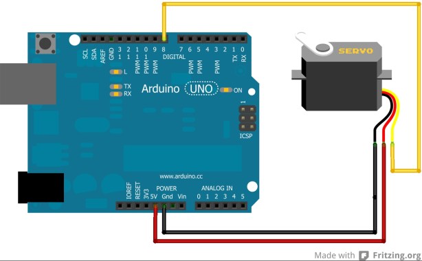
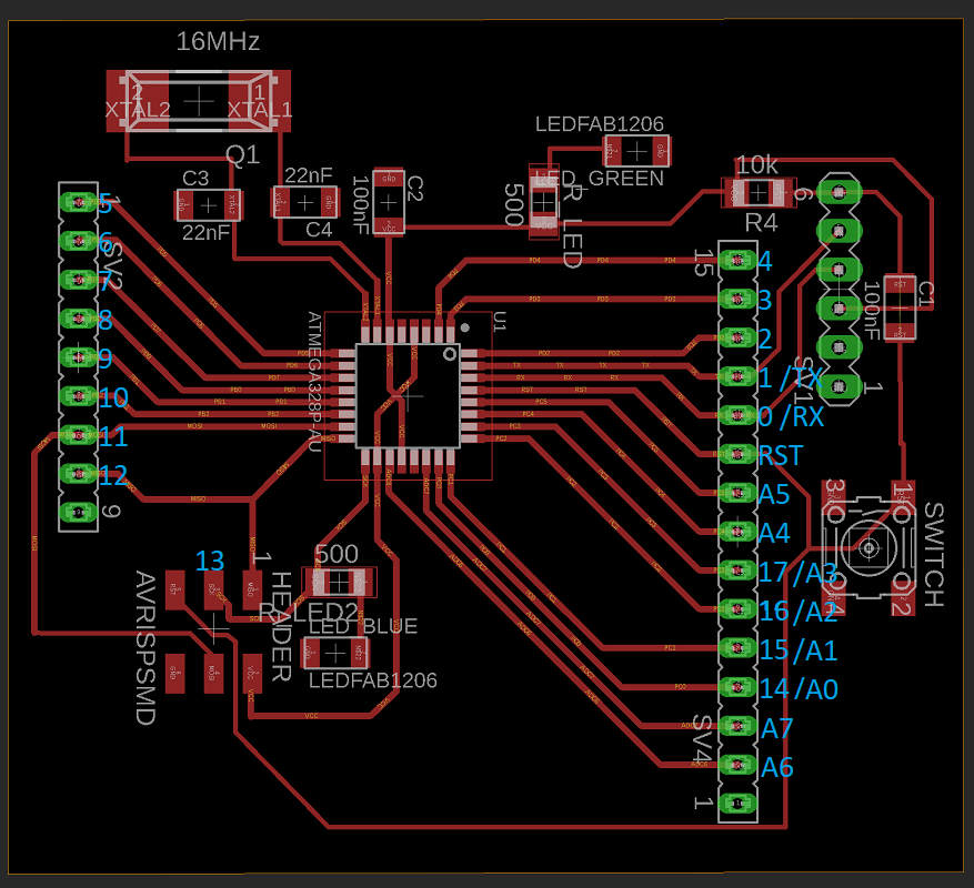
So See here the pin numbers of my self-developed board. How I made this you can read in Assignment week number 10.
After connecting the servo to my board I could concentrate at the software. Here I found a great guide at funduino.de. See below a first example of how to control the servo.
#include <Servo.h> //that incudes the servo library, that controlls the PWM

Servo servoblau; //here you have to name yout servo, it is importent if you want to controll more than one servo

void setup()
{
servoblau.attach(8); //my servo is attach at pin number 8, it has to be a PWM-pin
}

void loop()
{
servoblau.write(0); //move the servo to the zero degrees position
delay(3000);        //wait 3s to get the servo in hin position
servoblau.write(90); //move the servo to the 90 degrees position
delay(3000);         //wait 3s to get the servo in hin position
servoblau.write(180); //and so on...
delay(3000);
servoblau.write(20);
delay(3000);
}
Here the servo in motion. (sorry for the bad quality, had bit troubles with my focus of this moving part.)
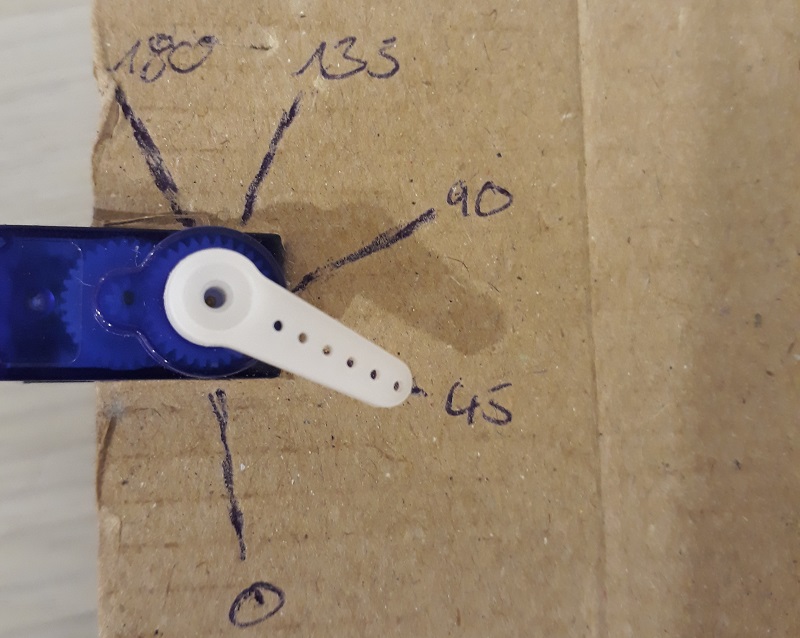
I wonder why the servos range is more than 180 degrees to I tried to get to smaller valued than zero and higher than 180. But that doesn’t make any difference. There is no failure in the software but the servo stops again in the 0 or 180 degrees position. So I took a look at the hardware again and noticed that there is a pin in the gear that makes the rotation stop. And on one side this little pin looks broken. (there was no chance to make a photo of it where you can see the broken pin). So lets try another servo:
As you see the new servo is stopping nearly exact at the opposite side of the zero degrees position. So I found the first mistake, but also the 90 degrees position is not exactly in the middle of the two end positions. But I didn´t found a real reason yet, but for the next steps and when I need the precision I have to remember this.
But now lets build a real system. I decided to build something like a RC-car control, because servos often used for systems like that. So I connected the servo with my board and added two buttons for left and right. To show when the button is pressed I added this two LEDs.
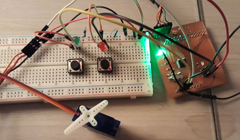
I had the edit the Software. See the final working software below. I just added comments to the new parts. How to use the buttons we learned last week 😉
#include <Servo.h>

Servo servoblue;
int motor=8;
int left=7;
int leftstatus=0;
int right=6;
int rightstatus=0;

void setup()
{
servoblue.attach(8);
pinMode(left, INPUT);
pinMode(right, INPUT);
Serial.begin(9600);                 //also added the serial monitor to find failures more easy
}

void loop()
{
leftstatus=digitalRead(left);       //read the buttons
rightstatus=digitalRead(right);
if (leftstatus == HIGH)
{
Serial.print("left" );
servoblue.write(180);              //if the left button is pressed, the servo moves to the 180degrees position
}
else
{
if (rightstatus == HIGH)
{
Serial.print("right" );            //if the right button is pressed, the servo moves to the 0 degrees position
servoblue.write(0);
}
else
{
Serial.print("Straight");
servoblue.write(90);              //otherwise the servo moves to the middle position of 90 degrees
}
}
} Add a LCD display
Next to motor, displays are a great output device to show for example any measurement values. So I wanted to include also a LCD-display to my system which shows the direction the motor moves. Therefore I used one of the standard Arduino LCD-displays: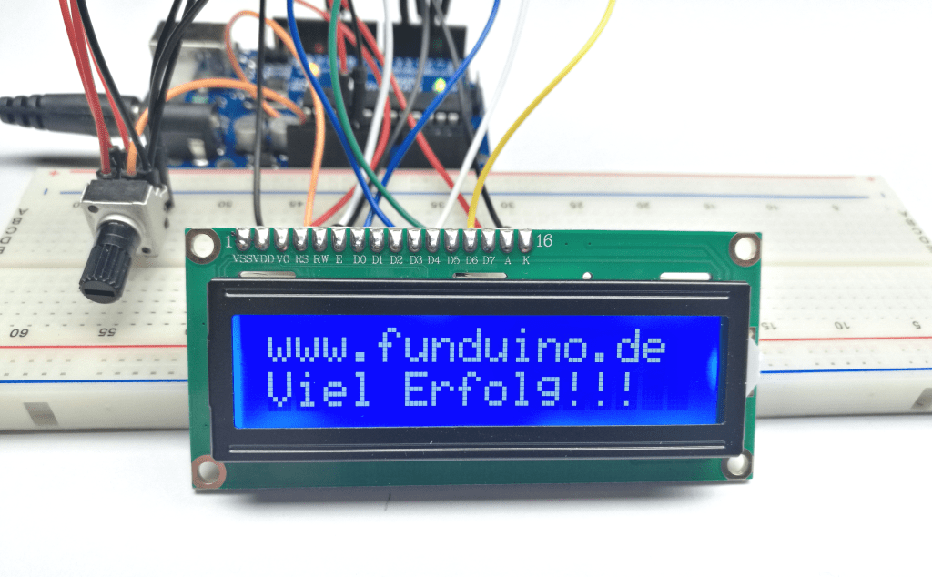
The display has two lines for maximum 16 letters. Find the compete datasheet below in the download section.
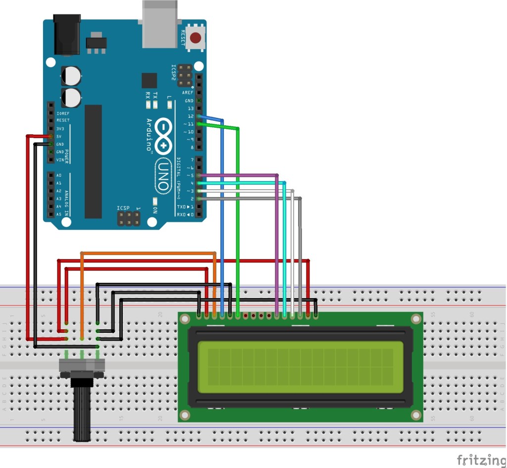
There is also a library in the Arduino IDE which I wanted to use. With my board there is no problem to use the Arduino libraries, but before I had to connect the display on the right way with my board. You find the scheme under funduino.de.Here again my own pin scheme is necessary to get the right connection as seen below:
The extra potentiometer is used to regulate the brightness. It is also possible to use a fix resonator, but I think is a good way to play around with the options of the display so I used it too.
AT funduino.de there is also an example software given, but it doesn´t work as it should. So I had to find another way it works. Luckily the LCD-display is a standard device of Arduino so there is also a example in the Arduino IDE. This example works well so lets take a look at it:
// include the library code:
#include <LiquidCrystal.h>


const int rs = 12, en = 11, d4 = 5, d5 = 4, d6 = 3, d7 = 2;
LiquidCrystal lcd(rs, en, d4, d5, d6, d7);

void setup() {
  // set up the LCD's number of columns and rows:
  lcd.begin(16, 2);
  // Print a message to the LCD.
  lcd.print("hello, world!");
}

void loop() {
  // Turn off the blinking cursor:
  lcd.noBlink();
  delay(3000);
  // Turn on the blinking cursor:
  lcd.blink();
  delay(3000);
} #include <Servo.h>
#include <LiquidCrystal.h>
Servo servoblue;
int motor=8;
int left=7;
int leftstatus=0;
int right=6;
int rightstatus=0;
const int rs = 12, en = 11, d4 = 5, d5 = 4, d6 = 3, d7 = 2;
LiquidCrystal lcd(rs, en, d4, d5, d6, d7);
void setup()
{
servoblue.attach(8);
pinMode(left, INPUT);
pinMode(right, INPUT);
Serial.begin(9600);
lcd.begin(16, 2);
}
void loop()
{
leftstatus=digitalRead(left);
rightstatus=digitalRead(right);
if (leftstatus == HIGH)
{
Serial.print("left" );
servoblue.write(180);
lcd.print("left"); //here the display gets its input
}
else
{
if (rightstatus == HIGH)
{
Serial.print("right" );
servoblue.write(0);
lcd.print("right");
}
else
{
Serial.print("Straight");
servoblue.write(90);
lcd.print("straight");
}
}
delay(10); //this short delay is neccesary to avoid flickering of the display
lcd.clear(); //clear the display, otherweise it only add the new direction word
} additional board design
I also designed a board for Output design. As output device i chose a mosfet and a led. To show the functionality of the mosfed i added a led and also a pin to connect a external device. See here the scheme.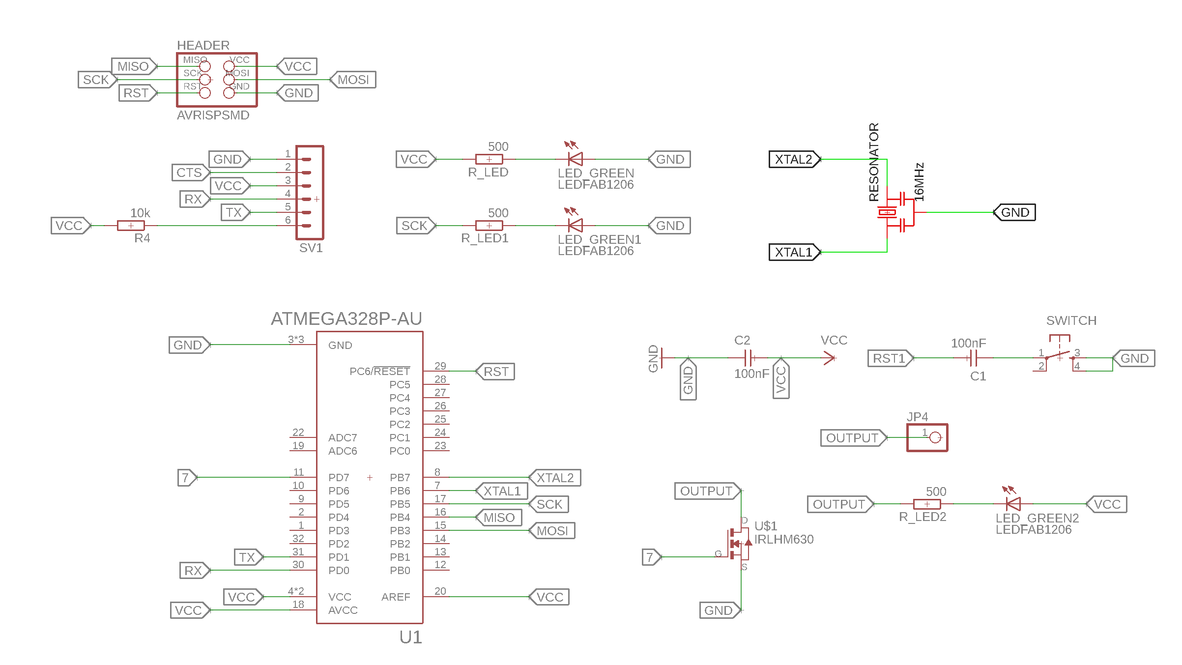
To show my board design skills I wanted to design a special board. The design isn´t very usefull but it allows me to learn more about different production proceses. So for example this board will be double sided and needs vias. See here the design:
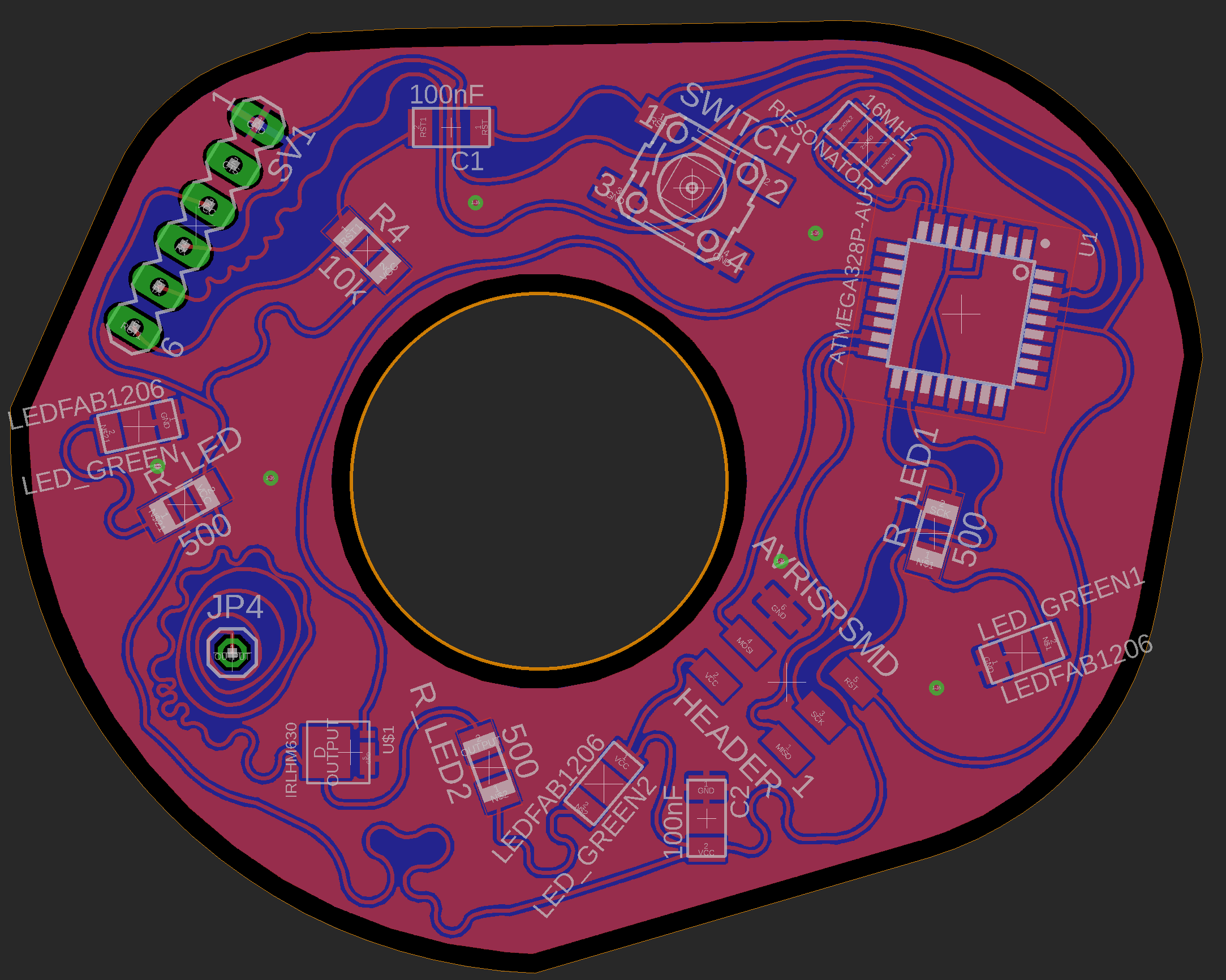
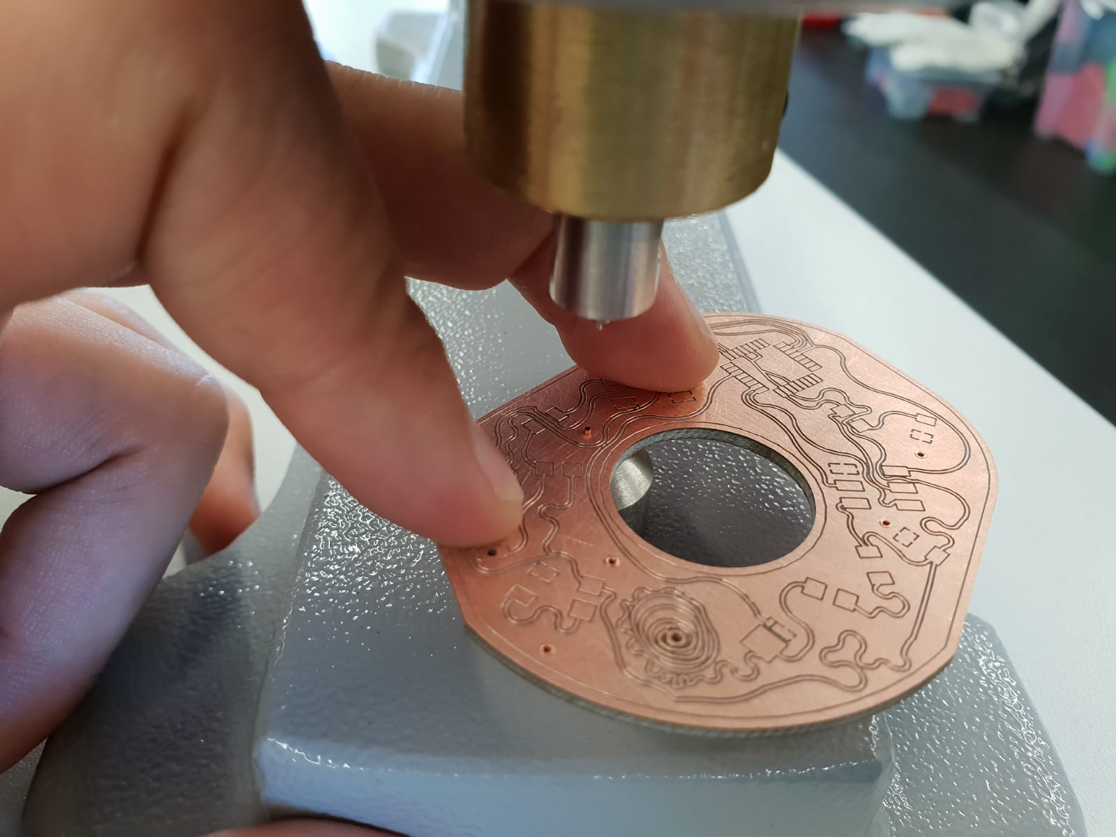
See here the finished board milled on both sides. The process of milling a double sided board is quite simple with our milling machine. You have to add passing marks befor the milling process. After finishing the first side, you have to turn the board material. With a camera the machine calibrate the correct position and starts milling the second side.
.jpeg)
.jpeg)
I used the backside as GND so i had to connect both sides via small rivets See the process below.
See here the working board. I used the simple blinking sketch to controll a mosfet which activates the speaker. I used the mosfet to controll electronic parts with another voltage like a relay.
Downloads
| Datasheet SG90 micro | download |
| Datasheet LCD Display | download |
| Output-Programs | download |
| Boarddesign | download |
