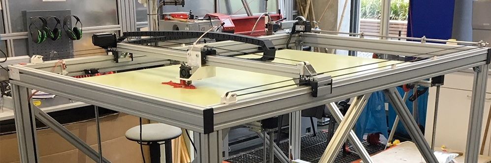
Big 3D-Printer
With a maximum volume of 150 x 90 x80 cm

Some of our Ultimaker
We´ve got more than 25 3D-Printer of diffrent types

Greeting
Our best employee in HRW FabLab
Assignment 13:
Networking and Communications
Task:
- send a message between two projects (group project)
- design and build a wired &/or wireless network connecting at least two processors
Work
For this assignment there were two options to build a network: serial communication or I²C. With the serial communication you can only connect two board with each other and there is no mast- slave relationship. The connection is quite easy and you only have to wire the for pins of the controller: Miso, Mosi, SCK, CS(1,2).I²C (Inter-Itegrated Curcuit) allows to use various masters and various slaves. It was invented by Phlips Semiconductor in the 1990s and needs only two wires (SDA-Data line and SCL-serial clock line). In difference to UART 'Universal Asynchronous serial Receiver and Transmitter' which needs in its bidirectional form TXD, RXD and GND as data lines, the I²C bus drivers are 'open drain'. That means that the connection lines have to be pulled down for a signal from 1 to 0. The lines uses 5V and waiting for transmitting a signal. For sending a signal the closed lines gets opened and pulled town to 0. The clock regulation allows the slave to hold the 0 for a while to extend the communication. This connection works only with small distances. I²C is usable without any license fees for a lot of applications since 2006. See here a scheme of the transmitting process:
For additional info I used the I²C-bus specification and user manual you find in the download section. I also used some Youtube-Videos to understand the process and learn more about some examples.
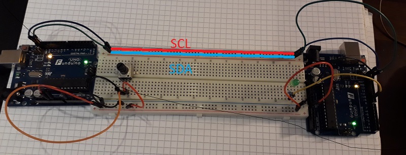
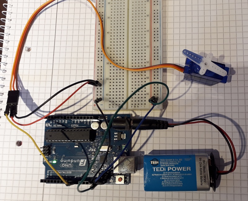
So I started wiring with two Arduinos. We had in this week some trouble with our milling machine so I was not able to build another self developed board. I wanted to start with a quite simple program: control the LED-brightness with the potentiometer via I²C. As you see in the picture I connected the necessary SCL and SDA line but also the VCC and GND. VCC wouldn´t be necessary (I show it later again with a external voltage source), but for a good connection both boards should use the same GND. The wiring of the potentiometer and a LED I showed a few weeks ago so I don’t reply it.
Couse I used the Arduino IDE I´m able to use a library which allows a quite simple connection. See my commented program below:
Master Code LED
#include <Wire.h>  //include library

int potPin = A0;   //integrate pin for potentiometer

byte sendData=0;    //add a byte with the name 'sendData'


void setup() {
 Wire.begin();       //start the library

}

void loop() {

sendData = map(analogRead(potPin),0,1023,0,255);  //set 'sendData' to the analog input of the potentiometer and map it to a value between 0 and 255

Wire.beginTransmission(4);  //choosen Slaveadress besides 0,1,2,3 and 120-127 and begin transmission
Wire.write(sendData);        //send the 'sendData' byte
Wire.endTransmission();      //end transmission

delay(50);                   //delay of 50 ms
}
Slave Code LED
#include <Wire.h>        //iclude library

byte incomeData=0;        //integrate a byte named 'incomeData'
int ledPin = 9;            //set the LED pin

void setup() {
pinMode(ledPin, OUTPUT);            //set the led pin as a output pin
Wire.onReceive(receiveEvent);        //receiving the Data
Wire.begin(4);                       //begin the communication and set the slave adress to 4 (the same as in the master program)

}

void loop() {
delay(50);                    //delay of 50 ms
}

void receiveEvent(int howMany)           //descripe the function 'receiveEvent'
{
incomeData = Wire.read();                  //set the incomming signals to the 'incomeData' byte
analogWrite(ledPin, incomeData);            //set the vaule of 'incomeData' as the analog output of the led pin
}After checking the program I used my self developed board for the communication. The build is completely equal, I had only to use the right pins of my board.
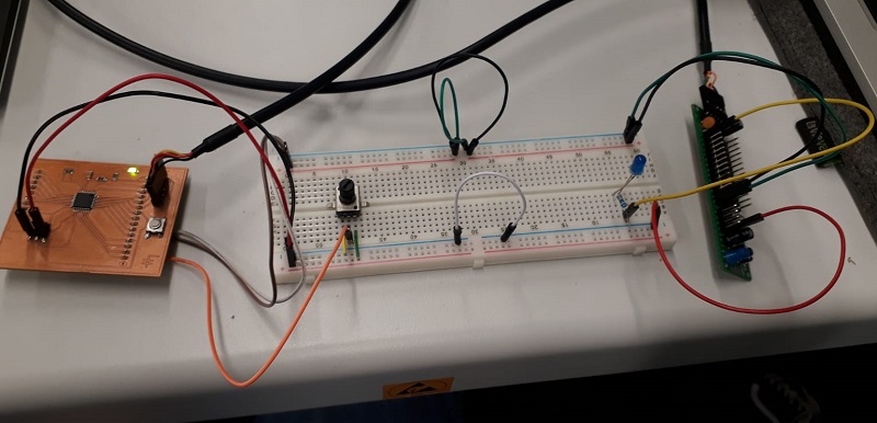
See here the working boards:
In the next step I wanted to controll a servo via the potentiometer. The wiring is nearly the same, i added only a servo and connected it to my PWM-pin.
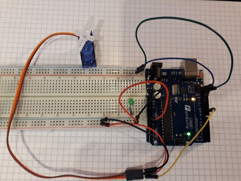
Let´s take a look in the programs. There were only some adjustments necessary.
Master Code Servo
#include <Wire.h>

//Master
int potPin = A0;

byte sendData=0;


void setup() {
 Wire.begin();

}

void loop() {

sendData = map(analogRead(potPin),0,1023,0,180);  //generate values between 0 and 180 for the Servocontroll

Wire.beginTransmission(4);  //choosen Slaveadress besides 0,1,2,3 and 120-127
Wire.write(sendData);
Wire.endTransmission();

delay(50);
}
Slave Code Servo
#include <Servo.h>   //include servo library
#include <Wire.h>

Servo myservo;   //name the servo
byte incomeData=0;
int servoPin = 9;


void setup() {
myservo.attach(servoPin);    //define attachment of the servopin
Wire.onReceive(receiveEvent);
Wire.begin(4);

}

void loop() {
delay(50);
}

void receiveEvent(int howMany)
{
incomeData = Wire.read();
myservo.write(incomeData);  //set the servo to the incomming degrees value
}At the end i wanted to try if the network works also with a external voltage source of the slave. So i used a batterie for the slave Arduino and it works the same way. I need this knowledge for my final project where I want to use the tracking of diffrent gyros to create a 3D mouse für people with disabilities.
Additional Board Development
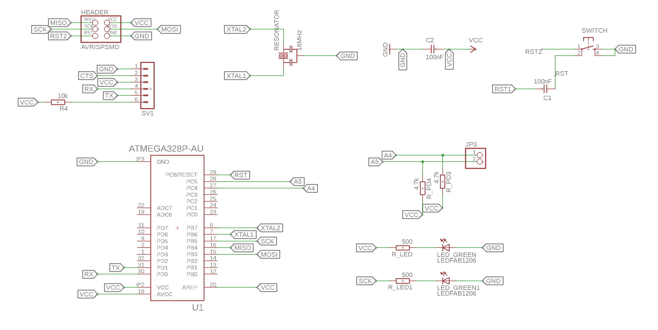
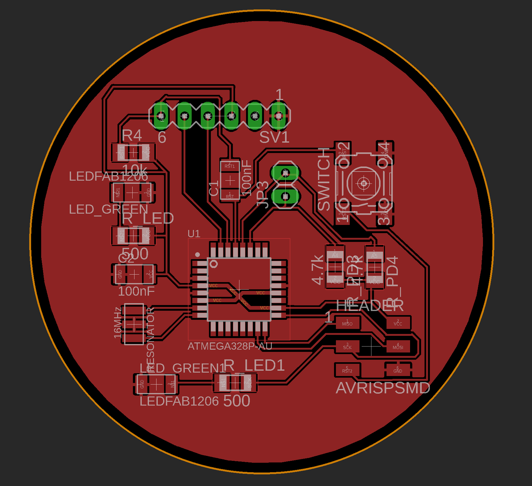
To show my design and production skills I developed a new micrrocontroller board for this networking week. See here my final layout.It is a simple board with SDA and SCL pins to allow connection via I2C. There are additional LEDs on it to show the functionality on a simple way. See the scheme below:
See the final design below:
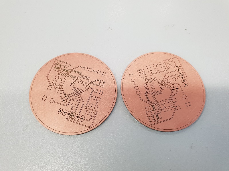
See heer the finished milled boards:
Downloads
| I2C-bus specification and user manual | download |
| Communication programs | download |
| Networking Board design | download |
