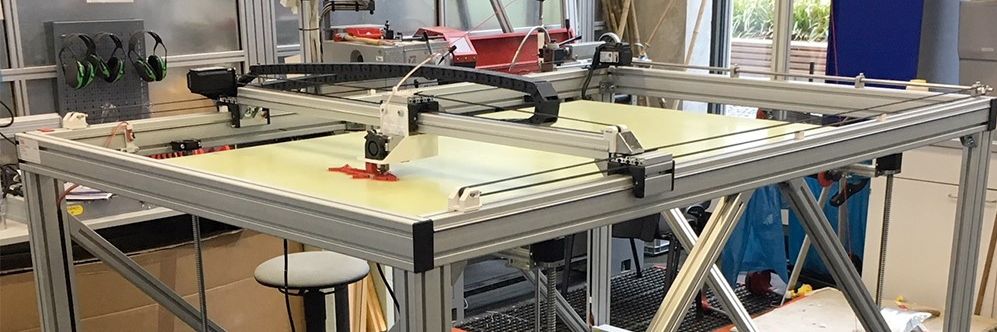
Big 3D-Printer
With a maximum volume of 150 x 90 x80 cm
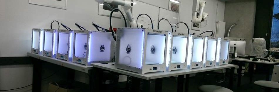
Some of our Ultimaker
We´ve got more than 25 3D-Printer of diffrent types
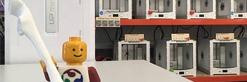
Greeting
Our best employee in HRW FabLab
Assignment 2:
Computer-Aided Design
Task:
Model (draw, render, animate, simulate, ...) a possible final project, and post it on your class page with original 2D and 3D filesWork
In this assignment I like to test some quite diffrent tools and take a look at their possibilities to find the best way to use it. I think each tool is usefull for different tasks. I will use commercial and open source tools to compare them to each other. As a first project I will try to sketch up the frame of my final project.Adobe Sketch on a Ipad
This tool is useful to safe ideas in first sketches. Because you can use a normal Ipad with a pen, it is possible to sketch nearly everywhere and at any time. So I think that will be a great tool for the first step.Adobe Sketch is a free software for Ipad. There are a lot of equivalent tools, but after testing a few different apps, I liked the adobe sketch the most. The possibility to use different layer make the tool more comfortable than the others.
There are various pen- and brushtools given whitch you can adjust in thickness, color etc. You dont need a extra pen, but with the own fingers I assert that the sketch become more inaccurate. With the pen you can draw like on paper.
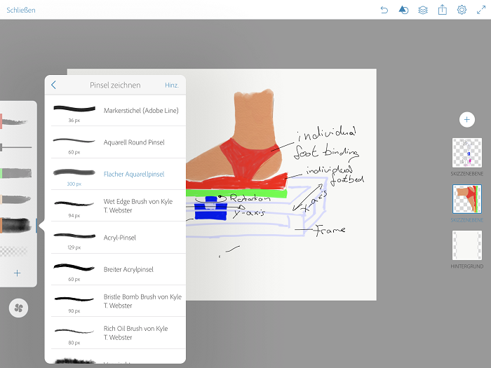
With different pen-tools and a lot of erasing I sketched a first version of my Frame:
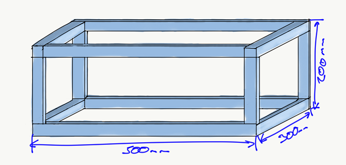
This sketch was made in 15 min after a short instruction tutorial. As you see it was quite difficult to connect all lines perfectly. There is no tool to sketch mechanical drawings. The dimensioning is handmade and has no connection to the sketch. The Adobe Sketch app is only a drawing programm. For the next step, the production these sketches are useless, but to present the idea this type of sketch could be a nice tool. So there could only .png files be generated.
Adobe AutoCAD mobile
This tool is more technical and allows to sketch more detailed and accurate. I used this software on my Ipad with the pen, too. I decided to scetch the same object than before to learn the differences.In contrast to adobe sketch adobe AutoCAD uses vectors to sketch. So there are not a lot of different colors but all lines are a defined vector so they could be edited during the whole process. There are only five drawing tools: line, polyline, rectangle, circle and arch. These tools are enough to sketch nearly any idea.
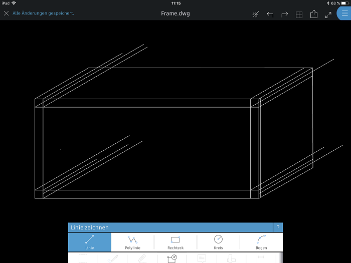
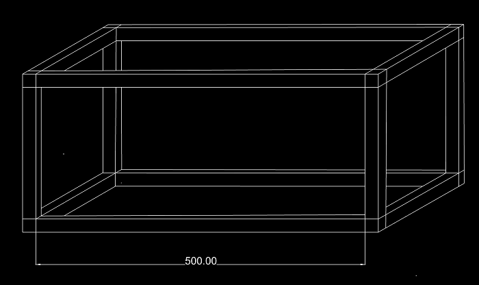
Each vector can manually definied with a lengh and a angle. This makes technical sketches a lot more easy than with the Adobe sketch. There is also the possibility to measure each detail. The software generates .dwg files whitch are vector files. So you can use the files to export them for exaple to a layercutter. So this tool is quite easy to handle to design 2D and functinal sketches. Here the final sketch:
Adobe AutoCAD is also a freeware tool for the iPad.
Sketch Up 3D
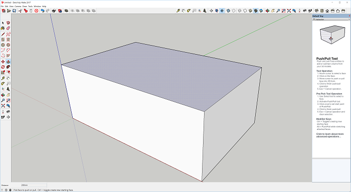
Sketch Up is the first 3D tool I´d like to use. It is a quite intuitive and uses just a few standart tools. It is open source and there are a lot of extencions available to add specific functions. The software is easy to learn so it is a good entrance to learn the frst steps in 3D-design. In our FabLab it is the first tool we show new members to design their first own prototypes for the 3D printer.There is a really good documentation of the single tools so i´d like to say everyone is able to learn this tool in maybe one hour. Sometimes there specitif shortcuts whitch make the work more easy, but they are nonessential. It is a simple drag and drop tool. The process is always the same:
- sketch on a surface
- pull the sketch in the third dimension
- edit the volumebody with extra tools
After this I removed the sides to get the cube I sketched with the 2D tools before. To get on each egde the same dictance I used the offset tool. After deleting some extra lines, my cube is finished just after 5 minutes and some clicks. It was more easy to generate a 3D model, than drawing it on 2D. Hiere the finished design:
For the easy geometric structrue I´d like to build, SketchUp is the best tool. If you´l like to build more complex geometrics SketchUp isn´t powerful enough and you need to use a more complex software. In the next step I skow you one of there "professional" tools.
OpenSCAD
OpenSCAD is a quite diffrent CAD-Software from SketchUp. It is a text-based software in witch you can design objects by describing it like coding a a website. There are just a few basic geometries you can define, but with the connection of a lot of single geometries it is possible to construct quite complex models. OpenSCAD is a freeware, here you can download it.As you see in th picture below the interface of OpenSCAD is subdivided in seperate working spaces. On ne left site there is the text-field where you code and program your objects. On the right site you see the "showroom". Here your code gets visualisied after rendering your code. Under this space there is the console where for example syntax-errors are displayed.
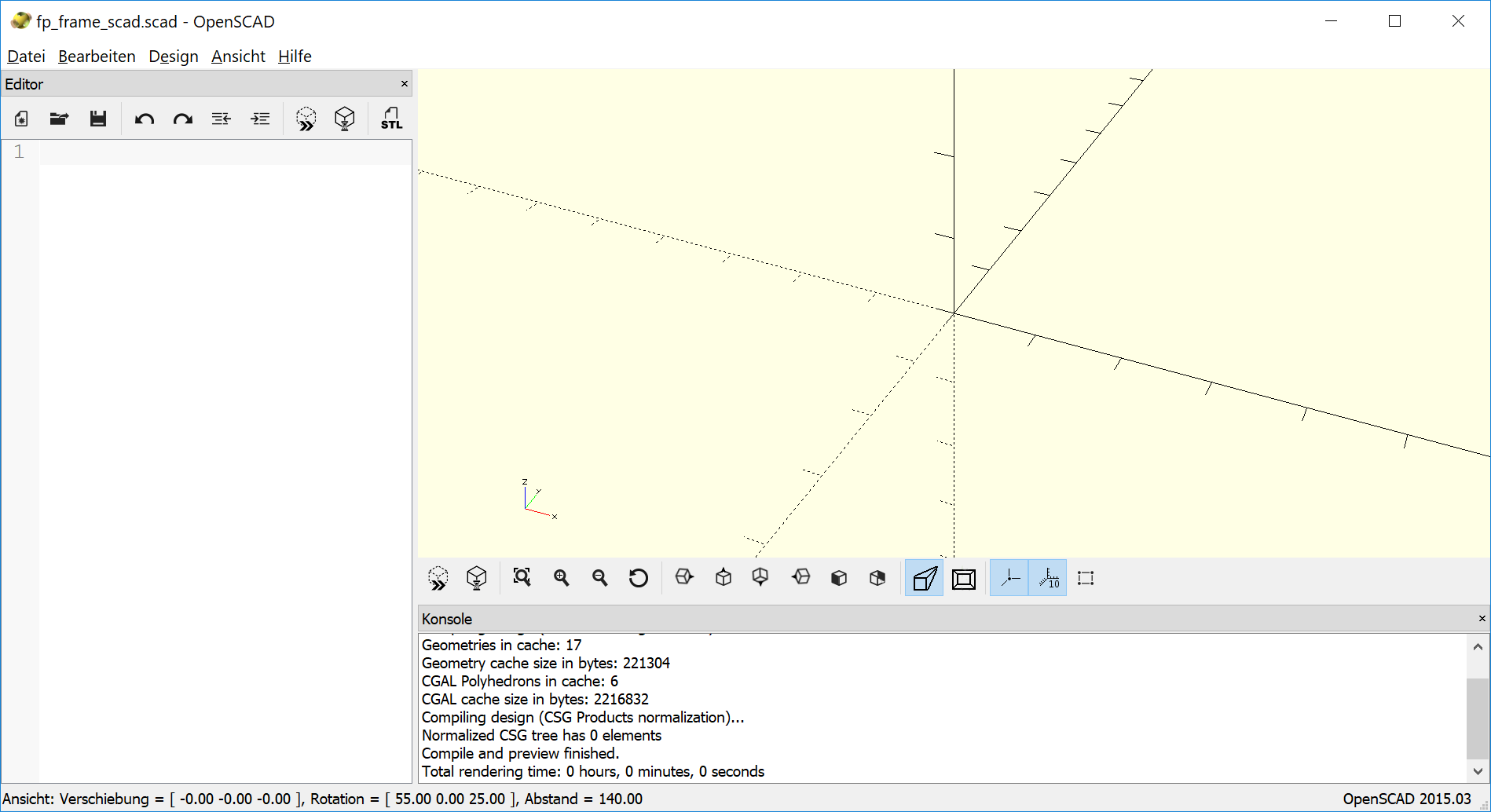
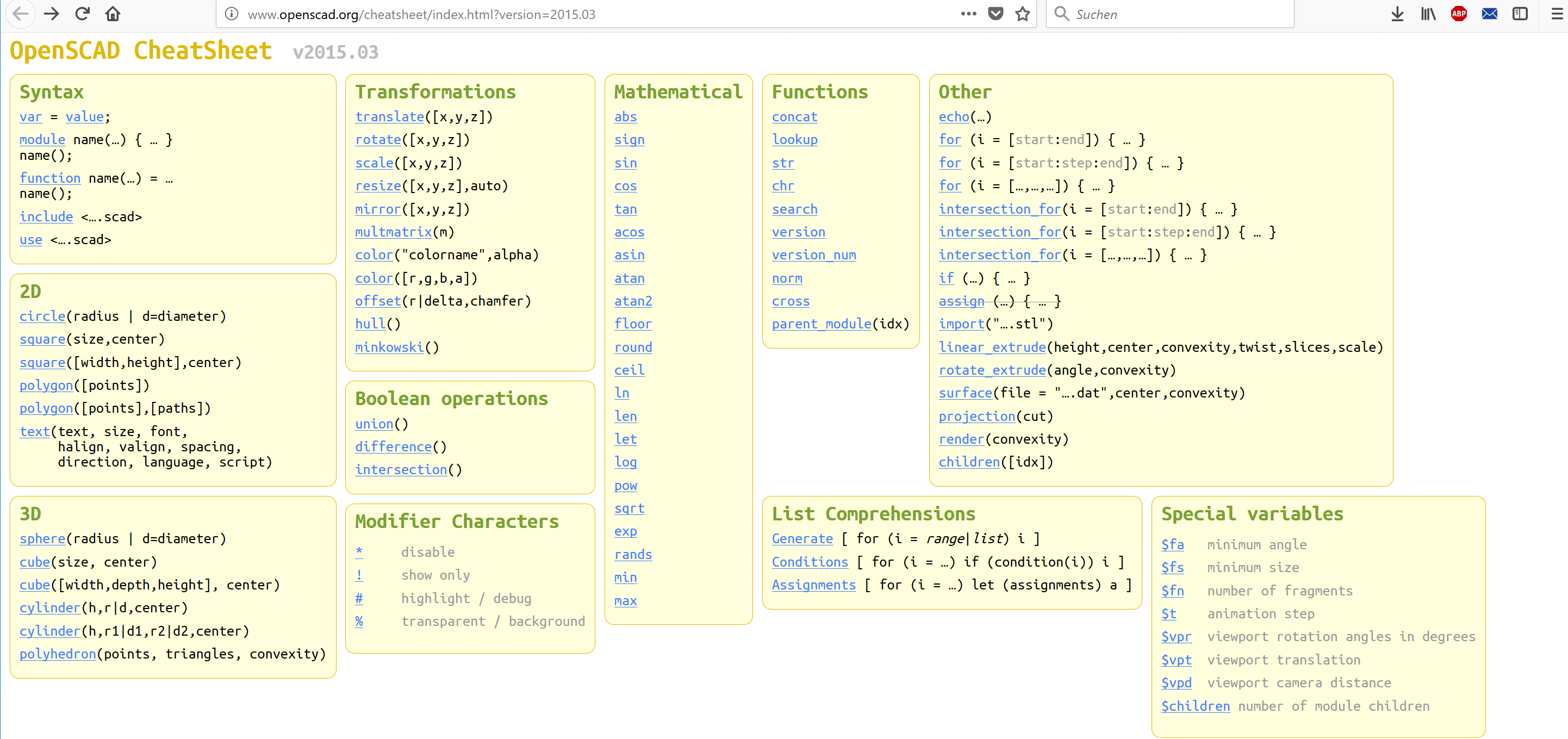
There are a lot of tutorials and examples you can find in the internet. OpenSCAD has a great documentation with examples, too. There you can find the basic comands and the documentation how to use and define them. See the list of the basic commands below:
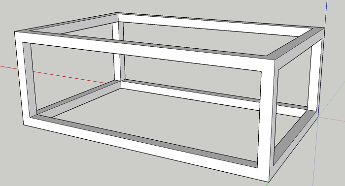
I tried to model again the simple frame of my foot-mouse to get an idea of the differences between the single software tools. I started with a big cube and subtracted three smaller cubes to get my frame. Because of my frame is symetric I used the option to center the single cubes. So it was really simple to build my frame. See the finished product below:
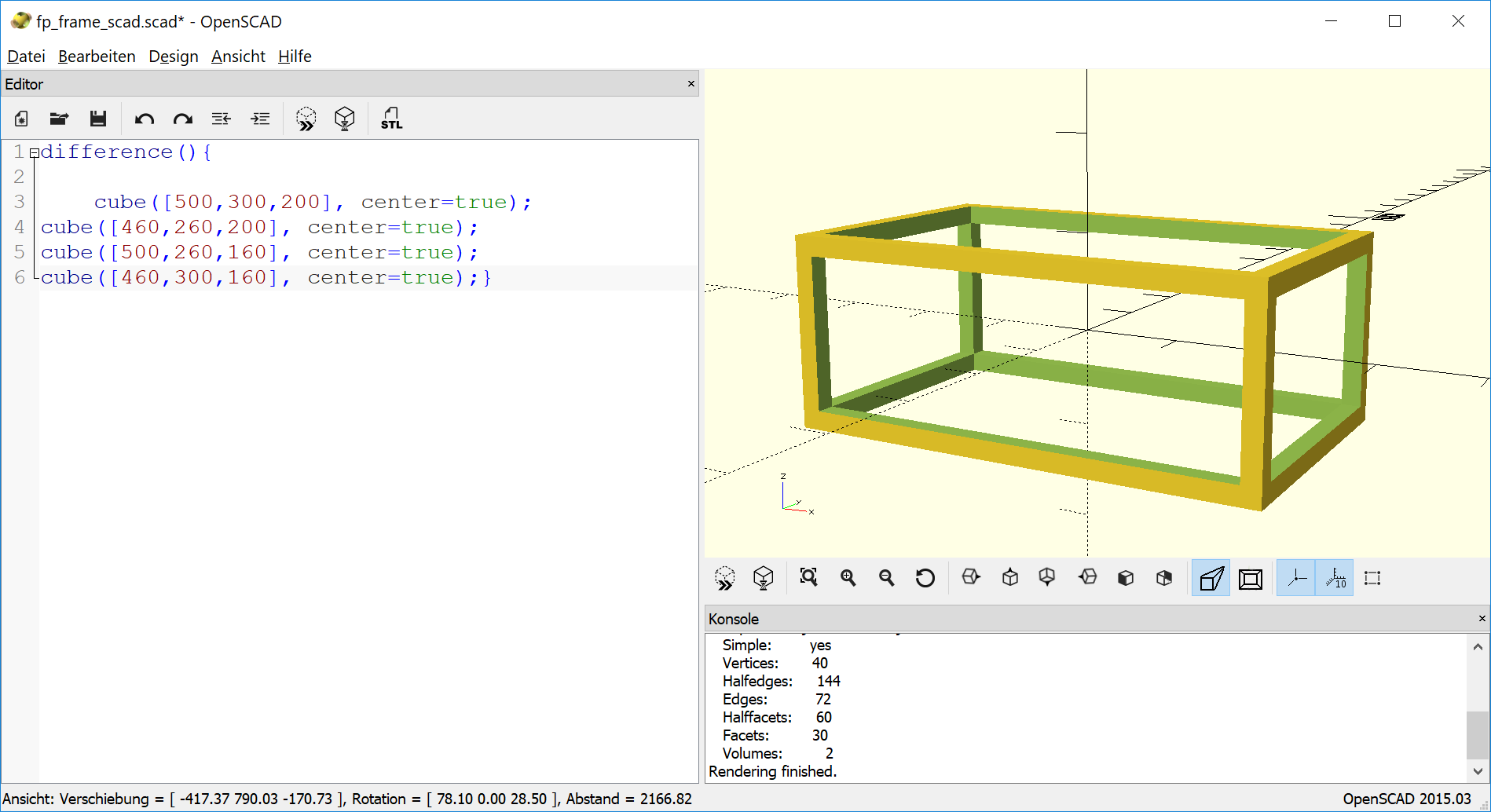
OpenSCAD is the perfect tool to build simple and mathematic objects. With a lot more time you also can build complex geometries, but in my first impression it is more for art-objects. It needs a new way of thinking to describe objects in a mathematic function. But I will try to build some more complex geometry in the future.
Fusion 360
Fusion 360 is a realy extensive software tool. For students it is free. It is comparable to commercial tools like SolidWork, Catia or ProE. The function of all these tools a quite the same. In my studies I learnd to handle with SolidWorks so I had some preknowledges in CAD. SO there was no big problem to work with fusion, nearly you can say, just the icons looks different. Taek a look at the surface of Fusion 360: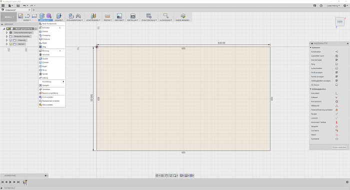
As you see there are lot of diffrent tools. In these tools are many options to adjust the single tool. It needs a lot of time to know all the functions and their possibilities. The biggest new feature is the chance to edit the measurement during the process. you can connect single geometrics with each other. For example you can make two circles centric and they will allways be centric even if you chance the diameter of one of these.
In addition to Sketchup Fusion allows a lot of more features like simulation, material or pressure check. But I designed again my cube to show the differences between the programs. I startet again with a massive cuboid and delete the rest to get my frame. You always start with a 2D sketch and make than a 3D action. Here the final cube build with Fusion360:
As you see the result of sketchUp and Fusion360 is the same but the fusion360 cube could be edited now again. For ecample Fusion allows to curve the corners or make the frame thicker by one click.
All in all you can say, all presented Software tools have pros and cons. You have to decide by your own what you want to to and how may time you would like to spend to see first results.
Simulation with Fusion 360
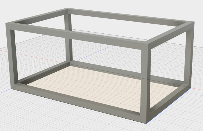
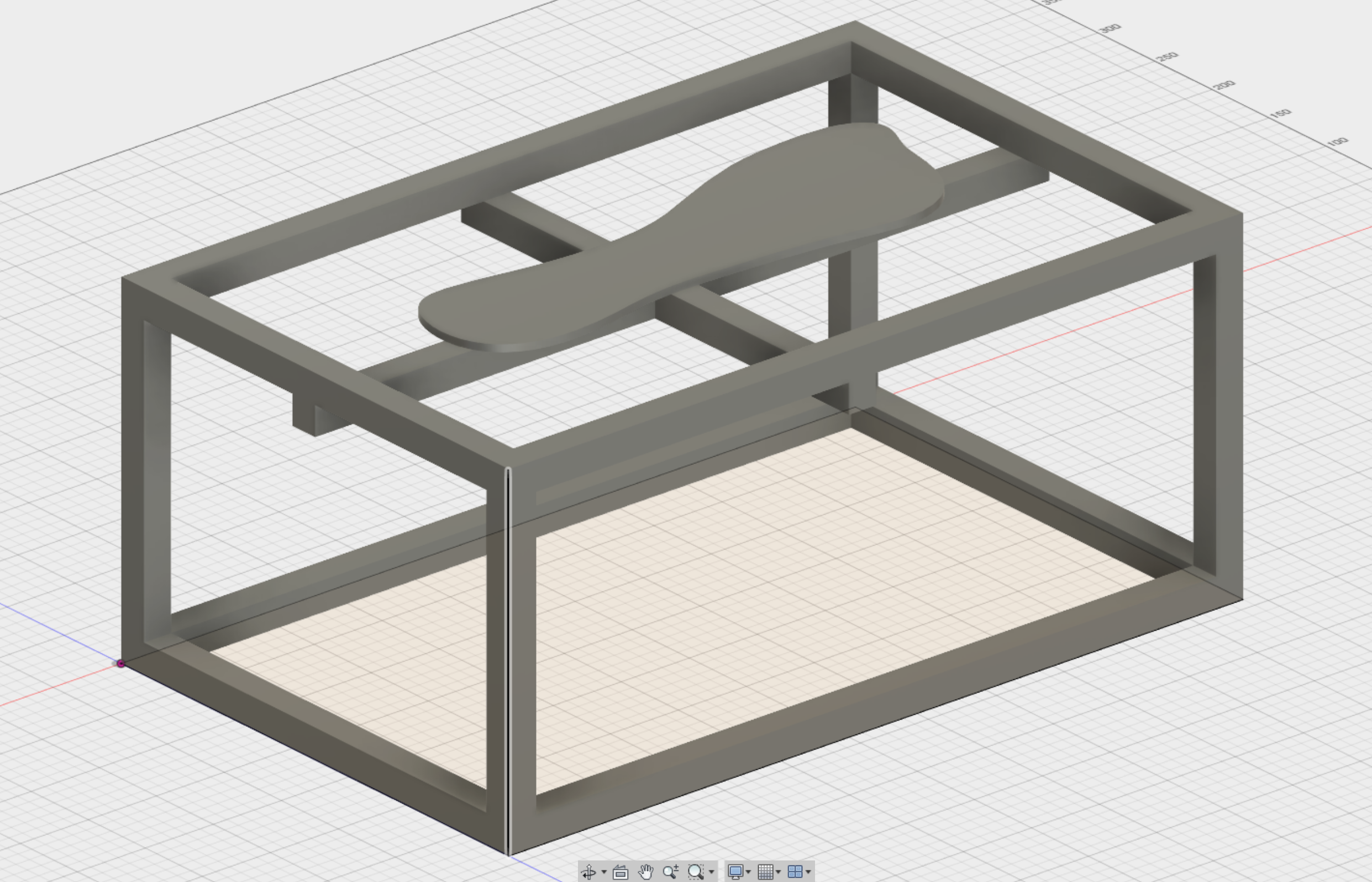
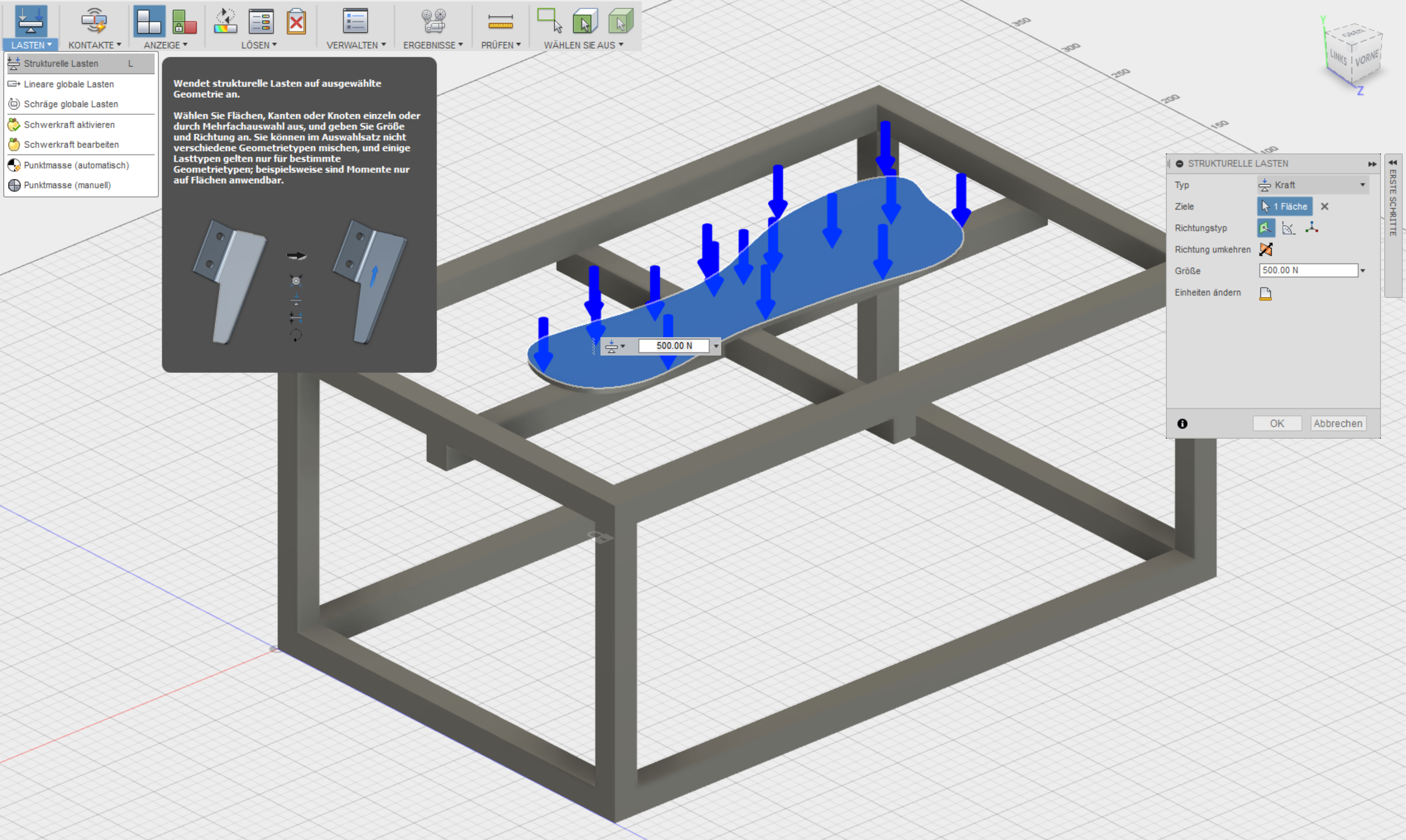
In the next step I´l like to try to learn more about the simulation and animation tools of fusion 360. All the other presentend software have no simulation and animation tools free included.In Fusion 360 animation is one of the main-tools you can choose. In the next step you have to decide witch type of animation you would like to generate. Fusion can candle different types of forces and thermic load. I choose in the first step the "static tension". In my simulation i´d like to find out the load on the frame. Therefore I added in my frame the simple construction of some extra bars and a sketch of a foot-bed (I didn´t realized a real setting with moveable parts. In this session the animation itselfs should be in the focus). See the picture below:
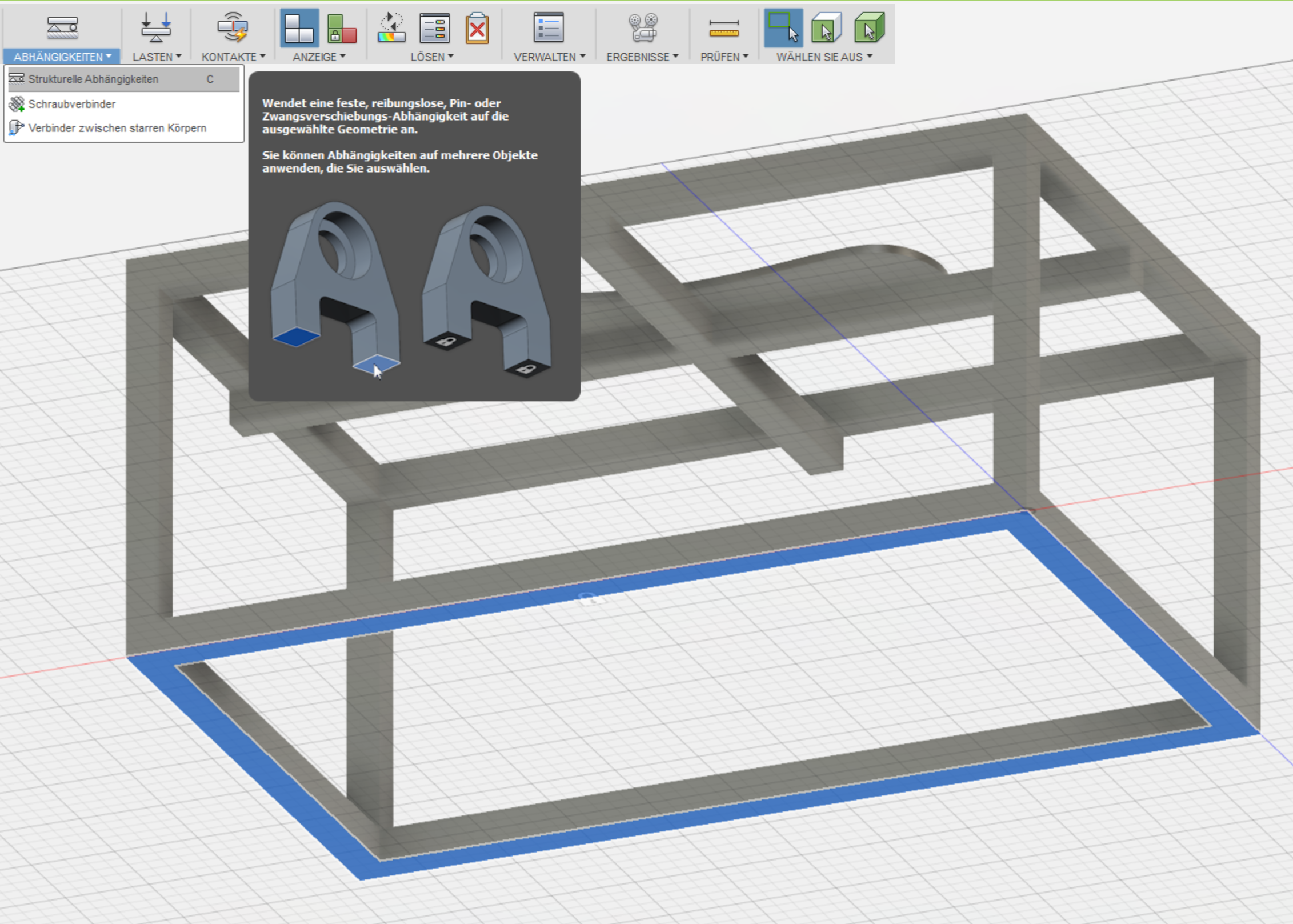
In the simulation you have to declare some dependencies. In the first step I set the bottom of the frame to fix, because in my use of the frame it will stands on the ground and shouln´t move. Fusion automatically choose steal as material, if you would like to change it you can choose one of the given materials under the point "material"
In the next step you have to define the force. In my setup the fource knits laminar on the complete foot-bet with a strength of 500N. That seems to be a lot, but my prototype shouldn´t break by a small incorrect use. See the neccesary inputs below:
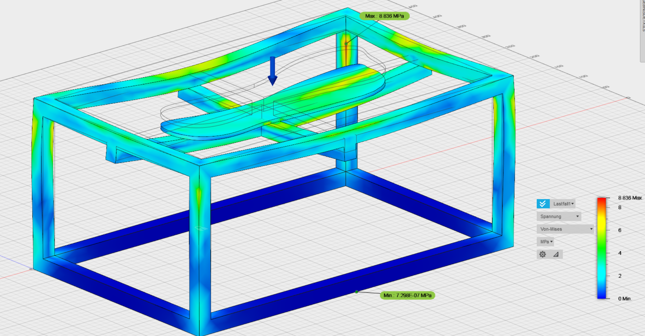
Now you can solve the simulation online or local. I choosed the online option because then you can work on during the solving. See the solution below. The deformation is in the presentation much more extreme than it woud be in the realitiy. The simulation offers a maximum of 0,25mm deformation in the left front of the foot-bed. But with this extreme deformation you can see how your model reacts under stress. In my setting it isn´t quite suprising, but is shows how strong these simple tool is.
After this Ii would like to animate the stress-test because I don´t have any moveable parts in my model so an animation would be quite lame. The animation of the stress-test you can find in the simulation-toolbox under "results". here you can make some adjustments about the speed of the test and the number of steps the fource should be divided in. I choosed the speed "slow" and make 50 steps. See the animation of the stress-test below:
The simulation-toolbox offers also the tool "formoptimation". With this tool you can optimize your model for spezific loading cases. You can define parts of your model witch shouln´t be edided, the rest could be optimized to less weigth/material and more stiffness. With my model that tool doesn´t made sence but I will use it to optimize my future parts for the 3D-printing.
Downloads
| 3D-Data | download |
