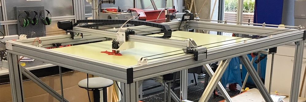
Big 3D-Printer
With a maximum volume of 150 x 90 x80 cm
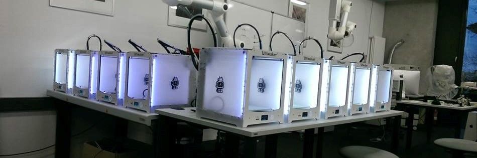
Some of our Ultimaker
We´ve got more than 25 3D-Printer of diffrent types
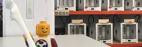
Greeting
Our best employee in HRW FabLab
Assignment 7:
computer-controlled machining
Task:
- test runout, alignment, speeds, feeds, and toolpaths for your machine(group project)
- make something big
Work
So let´s start so build something big. First of all I had to check the available milling machine. We at the HRW-FabLab haven´t a big milling machine jet (we are looking for a large hall at the moment, 200qm are not enough anymore) but our friends in Kamp-Lintfort allows us to use theirs. They have got a elsign EasyWorker MasterPro with a maximum working area of 2600 x 140 x 300 mm.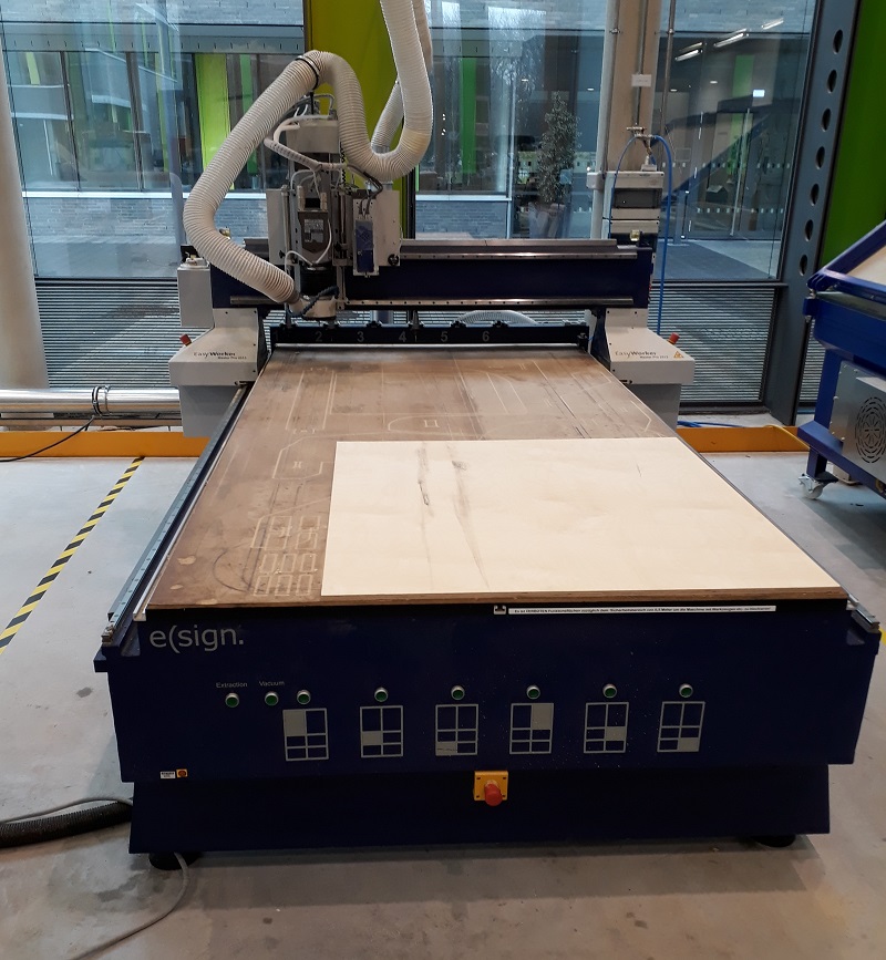
In our Lab we have no option to hang on the jackets of our visitor so I decided to Build a coatrack. Se my finished design below.
But after a night of sleep I thought that the design was not really well done. The both plates which builds the stand have to cut vertical up to a meter. That can easily ends in splitting plates. Also the transport of the 1950mm long parts would be a huge problem. So I decided to build a smaller but even big thing. So my next design was a simple tablet which I always misses at home. So why don’t build one by my own?
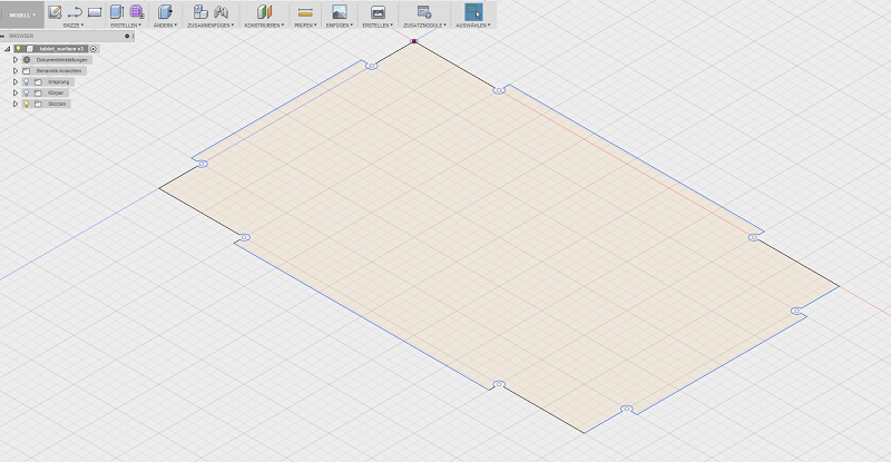
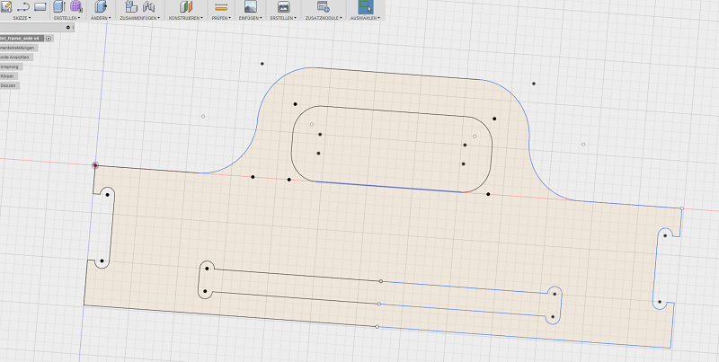
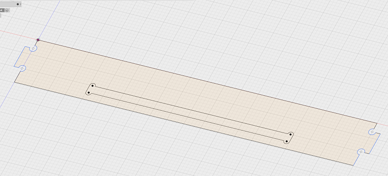
I used Fusion 360 to design my tablet. I explanied the working process of fusion in the Computer-Aided Design - Week. I also used the parametric design, because I have a lot of equal vaules. So I tried to design a huge Press-Fit system. So I had to insert the thickness of my planned woodplate and the diameter of the cutting bit in my design. See the single design parts of my tablet below.
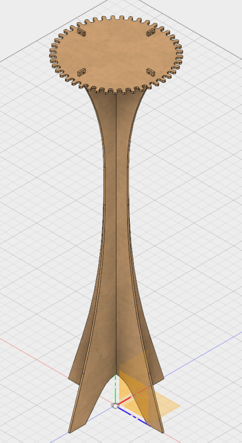
See here the connected tablet with all parts. Thats how it should look like.
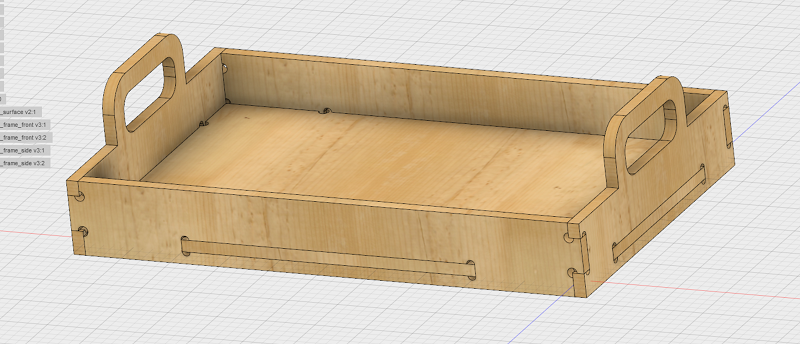
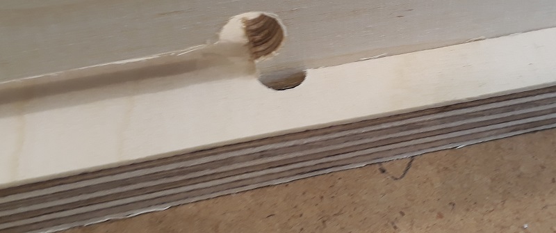
In my building center I only can find 12mm multiplex wood so it will be a quite strong tablet. I also had to edit my design, becouse I planned a thickness of 9 mm. Because of the paratemtric design that was only a fews clicks. The design includes the fact, that I wanted to use a 6mm cutting bit. So I added these 8mm holes in each inside corner to avoid postwork. Find the data in the download section below.
I exported the sketches as .dxf parts from Fusion360. After that I had to do some steps in Rhino to avoid double lines and dividing the files in diffrent layers to separate in- and out-lines. After that step I could start the process.
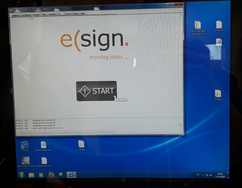
First I had to unlock the control center and start the elsign program.
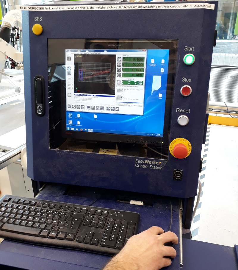
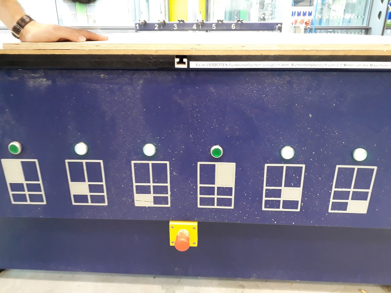
That is the control center with some additional buttons to interrupt the process quite quickly.
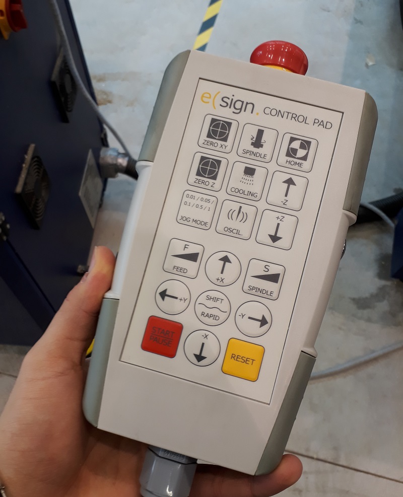
This is the hand control with which you can move the milling spindle by hand. In the next step I needed it for the definition of the zero point. But first the machine needs to drive to the home point.
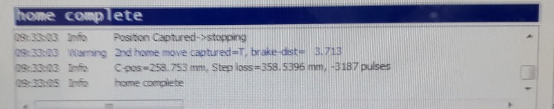
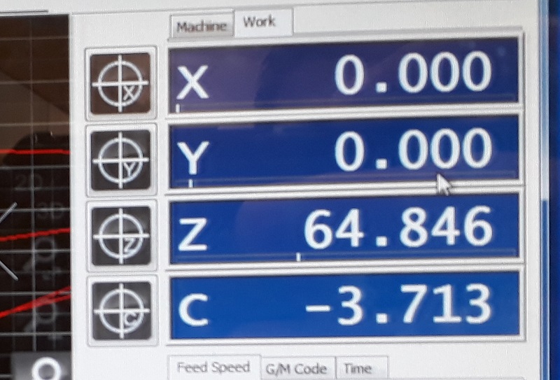
After the machine goes automatically to the home point the control window show the new status.
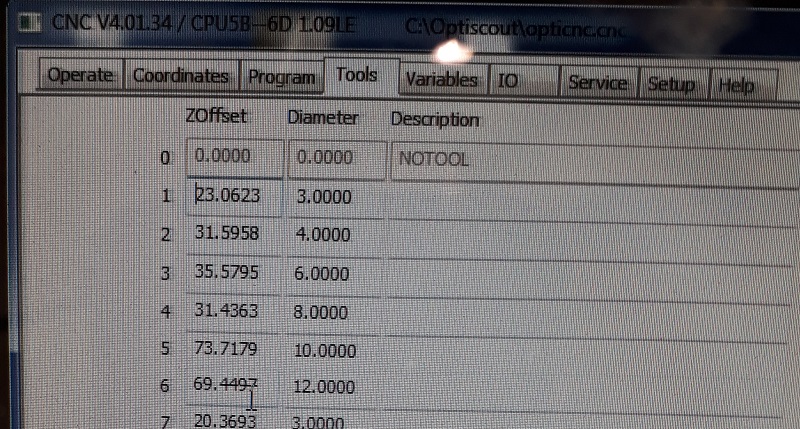
Before setting the zero point I had to check the right tools. I will work with the third tool with 6mm. with my design that is a good choice.
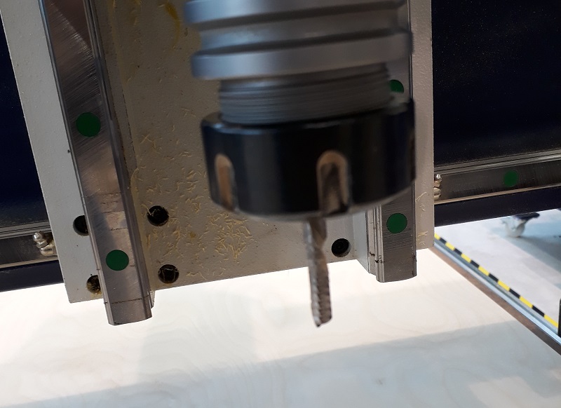
See here the tool. Next step to drive the spindle with the hand control panel to the right corner. That is where the internal X and Y-axis starts.
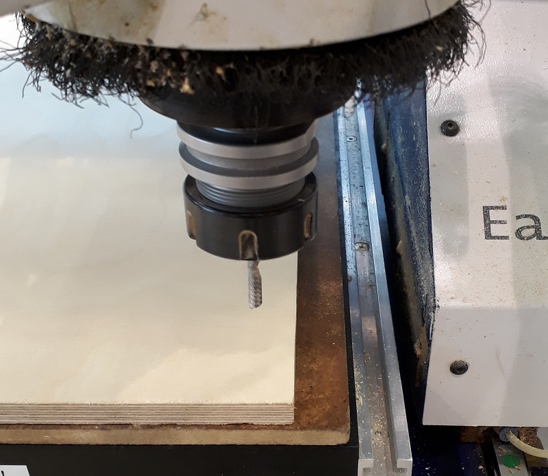
After driving the machine to the right corner as you see in the picture I can set the zero point for the X and Y-axis.
Not the actually point is the starting point for all milling processes. Only the Z-axis is missing.
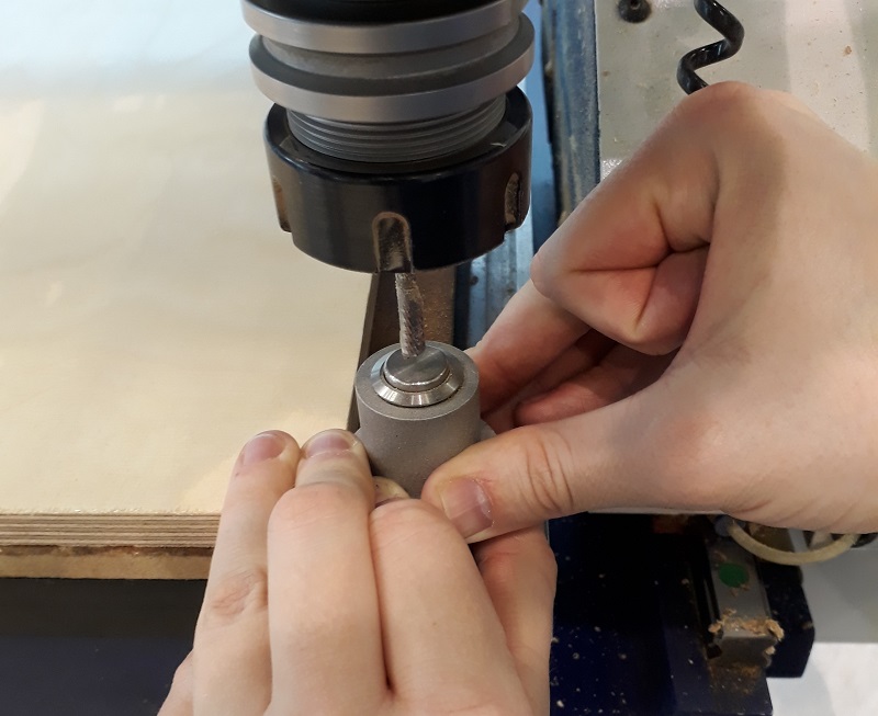
For the Z-axis there is a special button. You place the defined button on the bottom of the milling bet and slowly go with the spindle down until it presses the button. Now your Z-axis is also leveled.
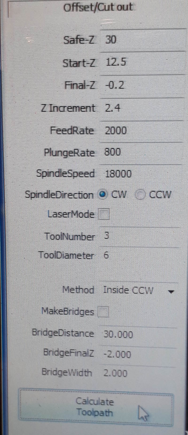
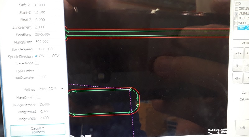
See here my setting for the milling process: Safe-Z means the distance between machine bed and tool during traveling.30mm will be more than enough with a 12mm plate. Start-Z is in which height the milling process starts. Here I chose a 0.5mm offset. Final-Z means the height where the milling process ends. I chose a negative value to get a clear cut trough the complete plate. Z Increments is the height which is milled with each step. So for my cut from 12.5 so -0.2 mm I needed six rounds for a complete cut. Feedrate is the speed of the spindle while milling. For my multiplex wood 2000 is a good setting. PlungeRate is the same for drilling holes. And at least the spindle speed is how mandy rpm the tool makes.
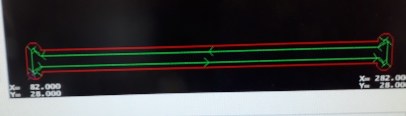
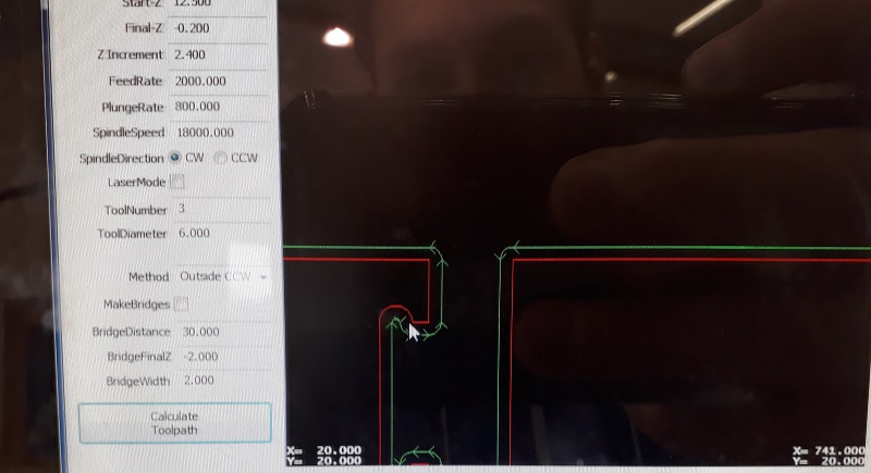
First I cut a test piece to test is the party fits to each other. Always start with the Inline cuts. See here the calculated tool path
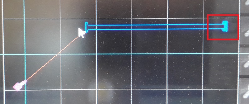
As you see in the red box the machine also shows the different circles which are needed to cut the complete wood.
But before starting the milling process I needed to fix the plate at the machine bed. The EasyWorker uses a vacuum which sticks the plate material at the bottom. The bed is split into six areas. I chose only the four where my plate was lying.
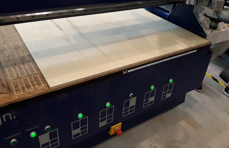
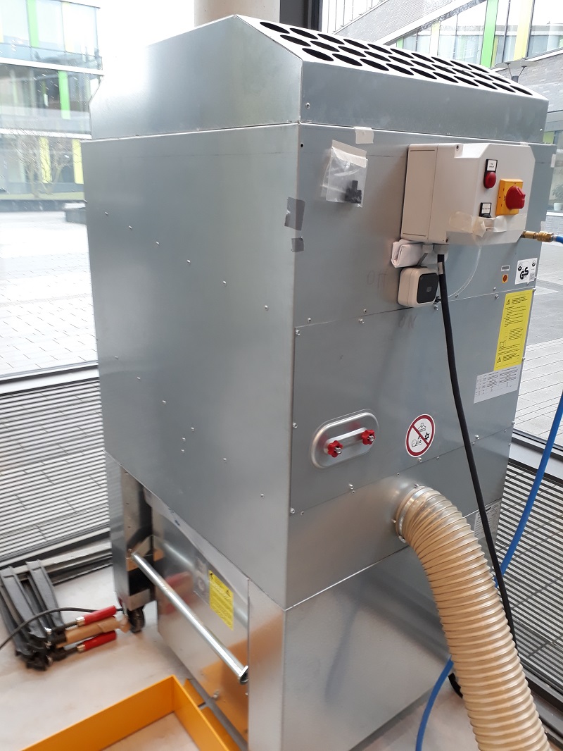
Also before starting the milling process I had to start the extraction of air to avoid a lot of dust.
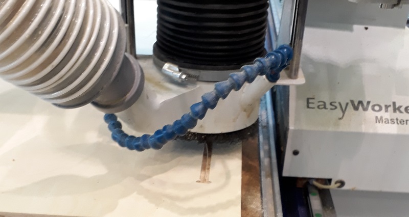
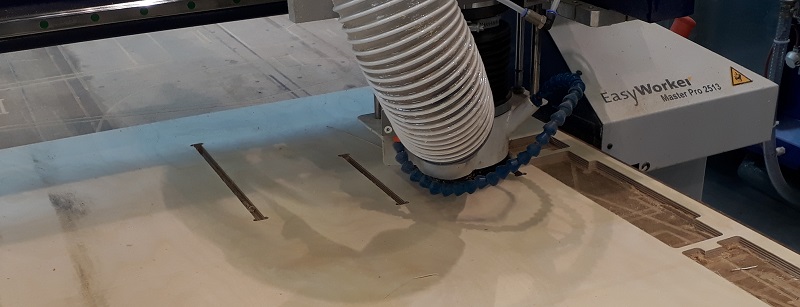
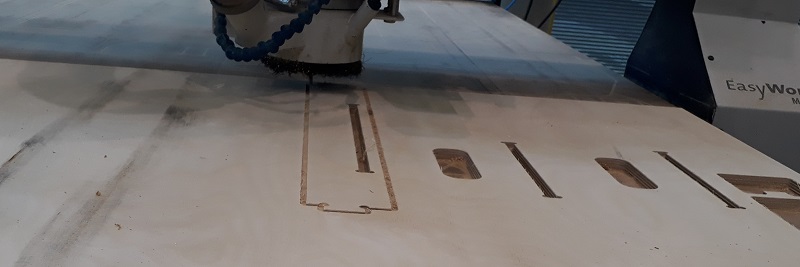
See here the first milled centimeters. The machine looks and sounds nice so the parameters are correct.
See here the first milled centimeters. The machine looks and sounds nice so the parameters are correct.
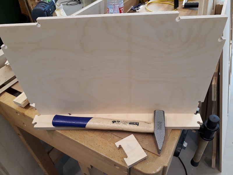
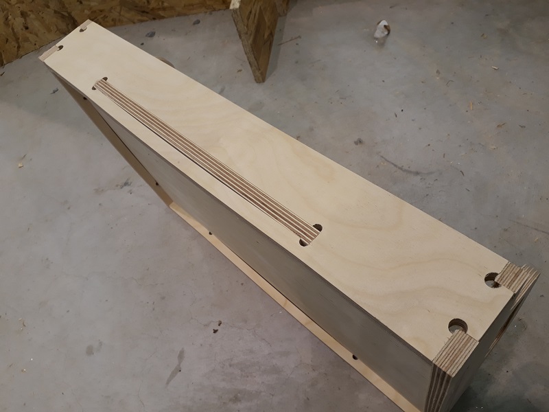
Aufter finishing my first parts I tried to put them together. As you see they fits quite good so I build a huge press-fit system. 😊
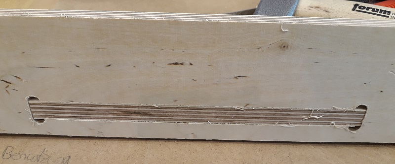
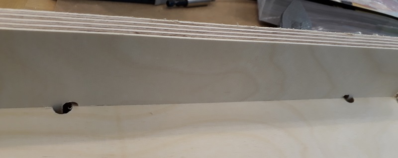
Putting the parts together needs a little bit of violence with a hammer but the connection gets quite strong so there is no screws or glue necessary. So now I can start the real production of my tablet.
Always control the right path of the tool. It is a usual mistake to mix inlines and outlines up.
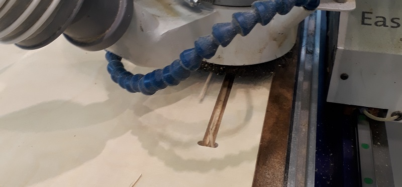
See here the machine during the final job. again first the inside cuts than the outside.
See below a short video during the milling process. specialy take a note of the sound. So a milling machine has to sound during milling wood.
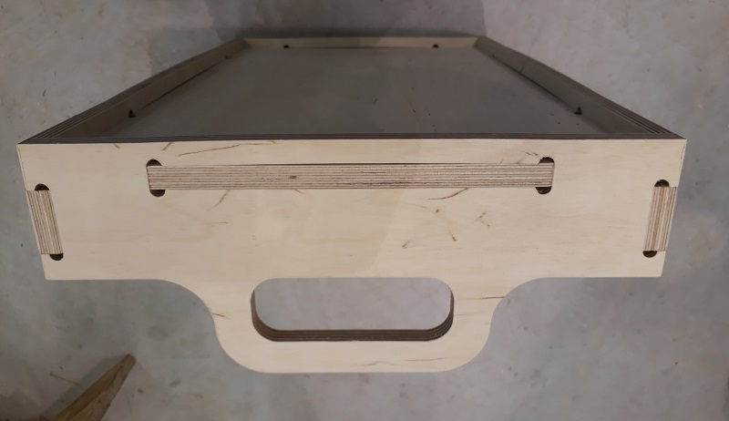
After cutting all parts and a little bit of post work is was time to put everything together. That was again hammer time.
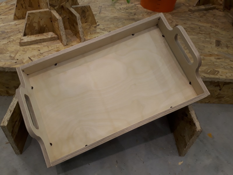
So See here my final product. It is quite stable and I used is now for some days and I can say: It works!
Downloads
| Tablet data | download |
| Coatrack | download |
| Tablet-CAD | download |
