Week 10: Input Devices
Before I start with the documentary I would like to say thanks to Tobias Poppe our instructor, who had helped me to restore the serial USB port on my computer. Thanks also to Peter von der Bey and Christoph Nieß for introducing me to the function of the oscyloscope.
Aleksandra's Fab Academy site helped me to add ATmega328p to the boards in the IDE. Thanks a lot for this.
This book was also very helpful in understanding the material during that week.
ATmega 328P AU, Excerpts from the Atmel ATmega328/P Data Sheet
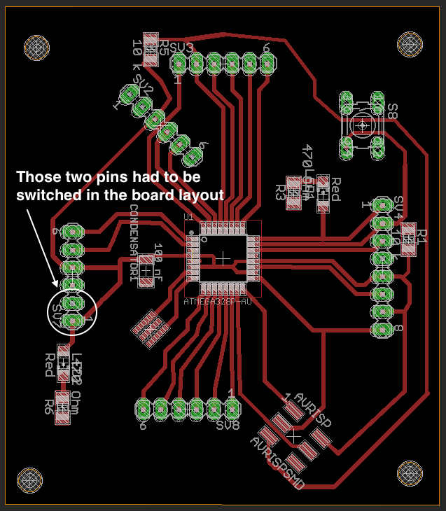
The following images shows the pin assignments of the ATmega328P_AU and the final layout of my ATmega328p board.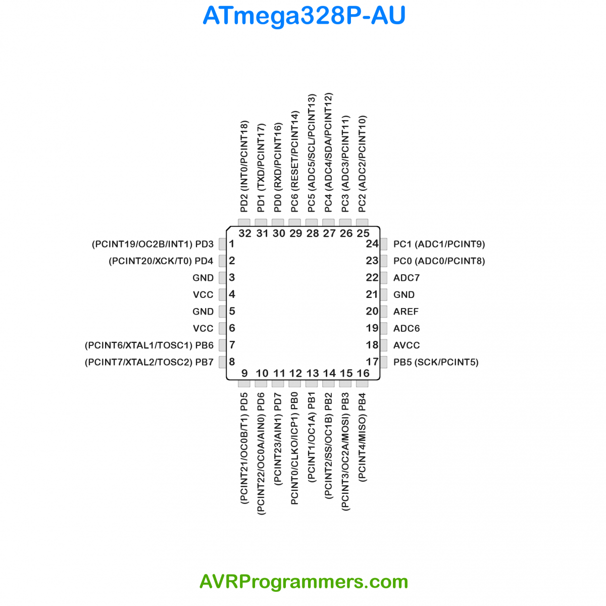
The Most ports are double and triple occupied and have the normal port function still special functions. The different pin designations and special funtions are described.
5.2.1. VCC
Digital supply voltage.
5.2.2. GND
Ground.
5.2.3. Port B (PB[7:0]) XTAL1/XTAL2/TOSC1/TOSC2
Port B is an 8-bit bi-directional I/O port with internal pull-up resistors (selected for each bit). The Port B output buffers have symmetrical drive characteristics with both high sink and source capability. As inputs, Port B pins that are externally pulled low will source current if the pull-up resistors are activated. The Port B pins are tri-stated when a reset condition becomes active, even if the clock is not running.
Depending on the clock selection fuse settings, PB6 can be used as input to the inverting Oscillator amplifier and input to the internal clock operating circuit.
Depending on the clock selection fuse settings, PB7 can be used as output from the inverting Oscillator amplifier. If the Internal Calibrated RC Oscillator is used as chip clock source, PB[7:6] is used as TOSC[2:1] input for the Asynchronous Timer/Counter2 if the AS2 bit in ASSR is set.
5.2.4. Port C (PC[5:0])
Port C is a 7-bit bi-directional I/O port with internal pull-up resistors (selected for each bit). The PC[5:0] output buffers have symmetrical drive characteristics with both high sink and source capability. As inputs, Port C pins that are externally pulled low will source current if the pull-up resistors are activated. The Port C pins are tri-stated when a reset condition becomes active, even if the clock is not running.
5.2.5. PC6/RESET
If the RSTDISBL Fuse is programmed, PC6 is used as an I/O pin. Note that the electrical characteristics of PC6 differ from those of the other pins of Port C.
If the RSTDISBL Fuse is unprogrammed, PC6 is used as a Reset input. A low level on this pin for longer than the minimum pulse length will generate a Reset, even if the clock is not running. Shorter pulses are not guaranteed to generate a Reset.
The various special features of Port C are elaborated in the Alternate Functions of Port C section.
5.2.6. Port D (PD[7:0])
Port D is an 8-bit bi-directional I/O port with internal pull-up resistors (selected for each bit). The Port D output buffers have symmetrical drive characteristics with both high sink and source capability. As inputs, Port D pins that are externally pulled low will source current if the pull-up resistors are activated. The Port D pins are tri-stated when a reset condition becomes active, even if the clock is not running.
5.2.7. AVCC
AVCC is the supply voltage pin for the A/D Converter, PC[3:0], and PE[3:2]. It should be externally connected to VCC, even if the ADC is not used. If the ADC is used, it should be connected to VCC through a low-pass filter. Note that PC[6:4] use digital supply voltage, VCC.
5.2.8. AREF
AREF is the analog reference pin for the A/D Converter. 5.2.9. ADC[7:6] (TQFP and VFQFN Package Only)
In the TQFP and VFQFN package, ADC[7:6] serve as analog inputs to the A/D converter. These pins are powered from the analog supply and serve as 10-bit ADC channels.
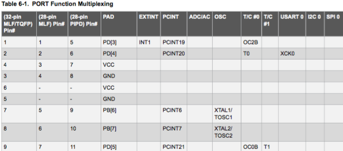
I/O Multiplexing
Each pin is by default controlled by the PORT as a general purpose I/O and alternatively it can be assigned to one of the peripheral functions.
The following table describes the peripheral signals multiplexed to the PORT I/O pins. Below is a part of the table with the pins I use:
Sonar Sensor HC SR04 Data Sheet
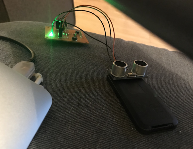
I decided to test the sonar sensor HC-SR04 because I would like to detect the window opening state using it. I know that this sensor is a bit to big for this purpose, but I did not start thinking about purchasing the sensor before, so the smaller one would not have been there on time until next rewiev.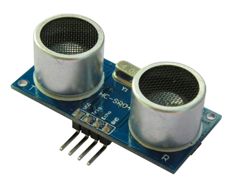
HC SR04
User Manual HC SR04
"How does the sonar sensor work?" from ( www.roboter-bausatz.de )
The sensor has four connections:
a) 5V(+)
b) GND (–)
c) echo
d) trigger
The 5V and GND connections are self-contained, providing power to the sensor.
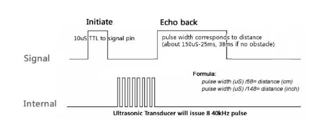
The pin "trigger" gets a short signal (5V) from the microcontroller board, causing a sound wave from the ultrasonic sensor. As soon as the sound wave hits a wall or other object, it is reflected and eventually returns to the ultrasonic sensor. As soon as the sensor detects this returned sound wave, the sensor sends a 5V signal to the microcontroller board on the "echo" pin. This only measures the time between the emission and the return of the sound wave and converts this time into a distance.
HC-SR04 Ultrasonic Module (funduino.com)
With the HC-SR04 ultrasonic module can measure distances between approx. 2 centimeters and 5 meters (with an accuracy of approx. 3mm). A microcontroller platform, e.g. Arduino IDE, is recommended to evaluate the data measured by the sensor. After triggering with a falling edge (TTL level), the module measures automatically the distance with a measurement time of 20 ms / interval and converts the measurement result into a PWM signal. This signal which can be read out at the output. This allows up to 50 measurements per second.
Here are some images of the HC SR04 from the user manual made by Cytron Technologies Sdn. Bhd. (All Rights Reserved)
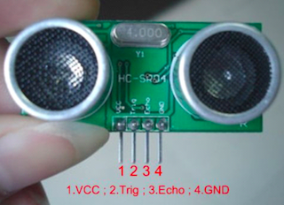
The module has a total of 4 ports, which are assigned as follows:
VCC: Power supply 5V
Trig: trigger input, TTL level
Echo: Output measurement result, TTL level
GND: ground connection
Applications
The HC-SR04 ultrasonic module can be used for the following tasks:
Obstacle detection
Distance measurement
Level indicator
Calculation of the distance:
The echo pin sends a HIGH signal after the measurement. The duration of the HIGH level determines the distance according to the following formula:
distance = ((duration_high_level)*(Sonic: 340m/s))/2
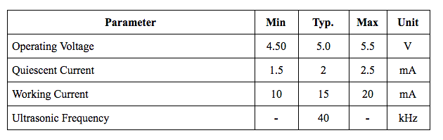
Details: Ultrasonic sensor for non-contact distance measurement
Power supply: 5V DC
Closed-circuit current consumption: less than 2mA
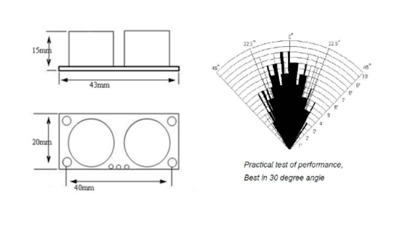
Beam angle: less than 15 °
Measuring distance: 2cm-500cm
Resolution: 0.3cm
Measurement is triggered when trigger is higher than 10μs high
Folowing images show the Function, the performance and the parameter of HC-SR04 sonar sensor.
Settings for Atmega328P using Arduino IDE: Programming the board using C
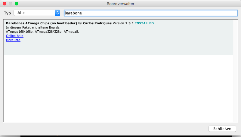
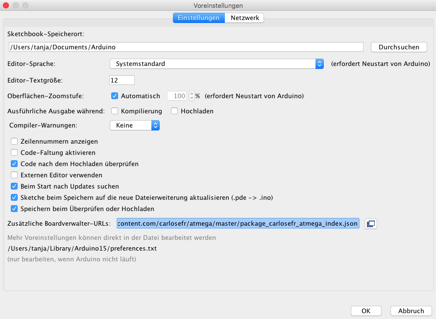
How to use Arduino IDE and self made ATmega328p board? Information about this I got from the Fab Academy site of my collegue Aleksandra. She shared the Information how to add the ATmega328p board to Arduino IDE and the Links to the site where we can find the needed library. I made some screens about how I added the library to Arduino IDE, which I show in the following.Those links I needed to include into the menue "Settings/Additional Board URLs".
Carlosefr: Tool Settings with Package Atmega328p
json-File
Programming the Data Read Arduino IDE
This is how the Arduino IDE code is built on:First I have to define the variables if I will need some and the pins which I am going to use for data reading of the sensor. After that there will be a part of the code called "void setup" which will be performed only once at the beginning. The part called "void loop" will repeat while the board is powered or while I press the "reset" button.
            int variableName = 0;


            void setup()
            {
                                // put your setup code here, to run once:

            }

            void loop()
            {
                                // put your main code here, to run repeatedly:

            }
Program code Below is the one that I've just taken over from Funduino as a simple code for reading the sensor via Arduino IDE.
            int trigger=7;                  // Definition of the pin which will read the trigger data
            int echo=6;                     // Definition of the pin which will read the echo data
            long duration=0;                // Definition of the variables I will need for calculation
            long distance=0;

            void setup()
            {
            Serial.begin (9600);            // Setting the daud rate (serial monitor) of the serial connection between ATmega board and                                 // my computer
            pinMode(trigger, OUTPUT);       // Definition of the pin 7, which became the name "trigger" to be an "output" pin
            pinMode(echo, INPUT);           // Definition of the pin 6, which became the name "echo" to be an "output" pin
            }

            void loop()
            {
            digitalWrite(trigger, LOW);     //  Set the trigger pin to low voltage (0 V)
            delay(5);
            digitalWrite(trigger, HIGH);    //   Set the trigger pin to high voltage (in my case 5 V)
            delay(10);
            digitalWrite(trigger, LOW);     //  Set the trigger pin again to low voltage (0 V) - means switch the trigger on for a short time
            duration = pulseIn(echo, HIGH);
            distance = (duration/2) * 0.03432;

            if (distance >= 500 || distance &<;= 0) // Look if the distance is to big or to short. If so print 'No measurement' into the print monitor
            {
            Serial.println("Kein Messwert");       // Print this string between the quotation marks and than go into the next line
            }
            else
            {
            Serial.print(distance);
            Serial.println(" cm");
            }
            delay(1000);                           // Make a pause for 1 second
Below you can find the code wehre I changed only the pin name and added the comments about each code line.
            int trigger=PD6;                  // This Pin bekomms the name Trigger will cause a sound wave as sooon as programm starts
            int echo=PD5;                     // If the Trigger Sound wave is reflected from the wall ...
                                              // and returns to the sensor, the sensor will send a 5V signal to this pin (echo).
            long duration=0;                  // Startvalue for this variable is 0
            long distance=0;                  // Startvalue for this variable is 0
            void setup()
            {
            Serial.begin (9600);              // This is the Baudrate 9600 Bit/second which I will use for the readings
            pinMode(trigger, OUTPUT);         //Pin named "trigger" will be used as output
            pinMode(echo, INPUT);             //Pin named "echo" will be used as output
            }
            void loop()                       // This part of the programm will repeat during the running time of the programm
            {
            digitalWrite(trigger, LOW);       // Pin PD6 (trigger) gets a 0V signal from the microcontroller board (ATmega328p)
            delay(5);
            digitalWrite(trigger, HIGH);      //PD6 (trigger) gets a 5V signal from the microcontroller board
            delay(10);
            digitalWrite(trigger, LOW);       //PD6 gets a 0V signal from the microcontroller board

            duration = pulseIn(echo, HIGH);   // This is definition of the variable "duration" which will count the duration of the state "high" of the Pin "echo"
            distance = (duration/2) * 0.03432; //Measured distance will be calculated using the half of the duration of the echo times the sound velocity in the air
            if (distance >= 500 || distance <= 0) // If the result of the measurement will be smaller than 0 cm or larger then 5 meter, there should be pritnted following massage: "no rading" as error massage
            {
            Serial.println("no reading");
            }
            else
            Serial.print(duration);              // Here will be printed the measurement of the variable "duration" and "distance"
            Serial.print("\t");
            Serial.print(distance);-
            Serial.println("cm"); ‚
            }
            delay(1000);

            }
I visualized the data in Arduino IDE using embeded serial plotter. These can be seen in the following image. Unfortunately I could not output the data in the serial monitor and in the serial plotter at the same time. Therefore, the measured values do not match the graph.
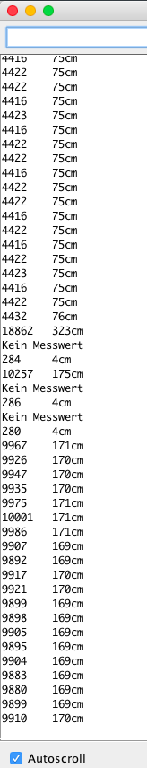
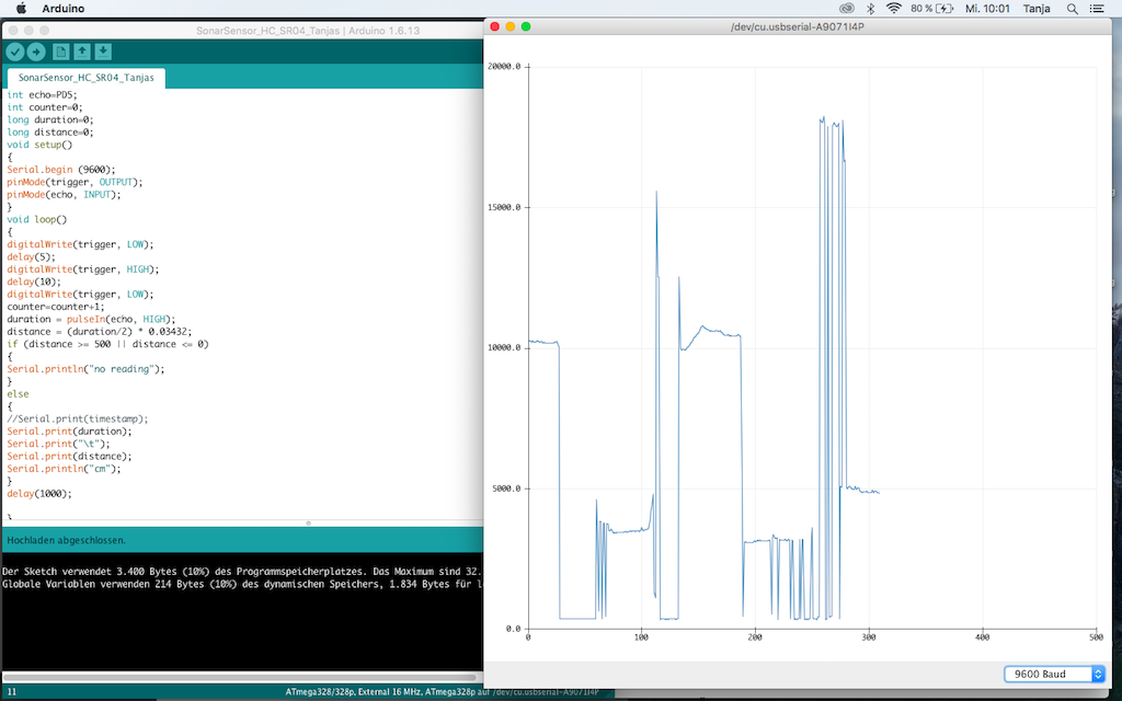
If moving from one direction to the other the sended trigger signal coud not be recieved by echo. Therefore the distance could not be calculated as intended. In that case the program output was also "No measurement".
Trouble shoting
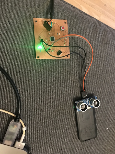
When I started trying to use other pins for power and ground (pin 3 and 4) than originally the sensor overheated !!! The reason for this was the change on my board layout which I had to make before milling the board to extend the GND area on the board. I switched the position of the GND and +5 V pins and have forgotten this later. I had luck because I disconnected the jumper wires fast, so my oard and the sensor For such cases it would be nice to make some labels on the board. It woud be usfull for me anyway, as I have to look on the pinout of the MCU each time I connect another pin.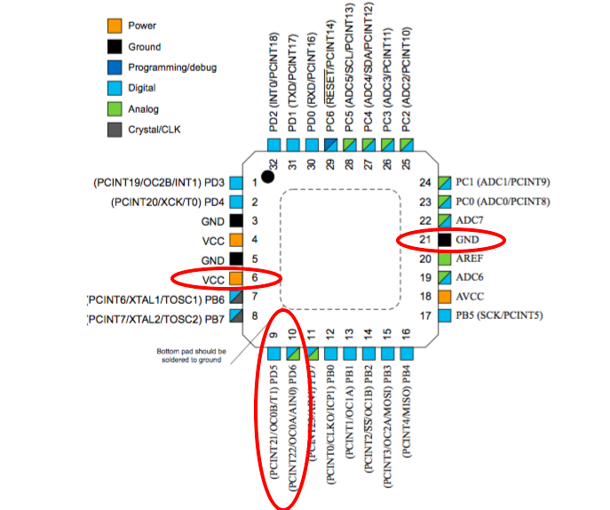
Testing Python with Fab Academy code
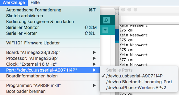
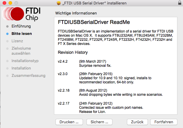
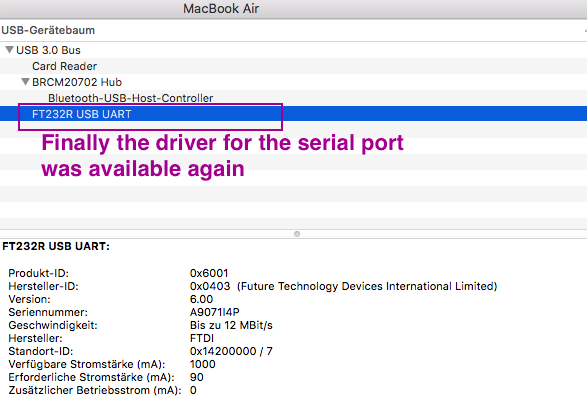
I have tested the sonar sensor using Arduino Uno board and after that I used my ATmega328p board. It seemd to be to confusing for my MacBook Air because after that I have got a problem with USB seriall port which was not there any more. Here is where our instructor Tobias Poppe helped me and installed a new USB seriall port om my MacBook Air. I decribe this instalation also at the beginning of the weekassignment number 12. It occured also later as I used Arduino Uno and my board alternating.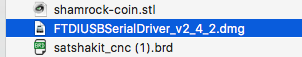
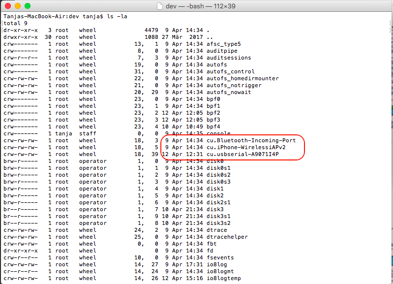
Florian Paproth, our instructor gave mir a tip about the labeling the USB-serial port as I later had a problem using Python serial connection because Python did not recognised the USB port labeld by Arduino. I taught that it was a special sign but it was simply a "I" sign. In the following list I sould see the real name of the port and could do the rihgt setting in the Python code.
I had a problem using the Python code from Fab Academy site. There was a smal dissonance in the Python code which I found out and fixed it.
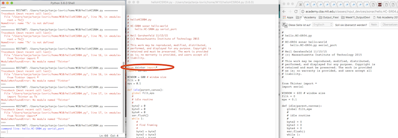
At some point of the code I could not go further. I made the code showing the graph, but it was not moving simultaneuosly to the moving of the sensor. I would like to find out why because I like Python programming.
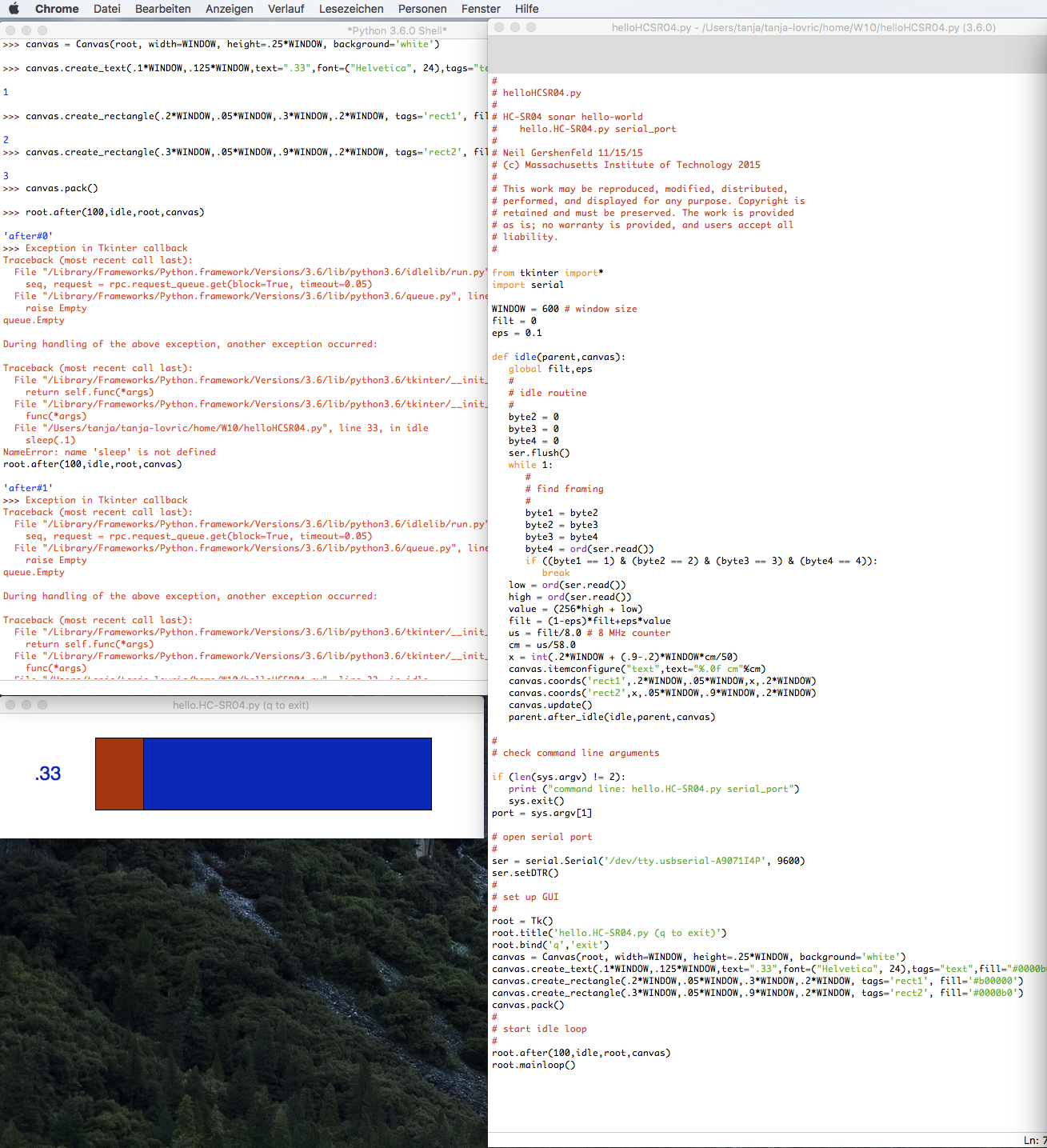
Later I tested just the measurement data output using Python and PySerial as to see in following movie. Interessting about the audio recording was that the sonar sound of the sensor coud be recorded by my smartphone.
Group Assignement: Sonar Sensor HC-SR04 data on Oscilloscope
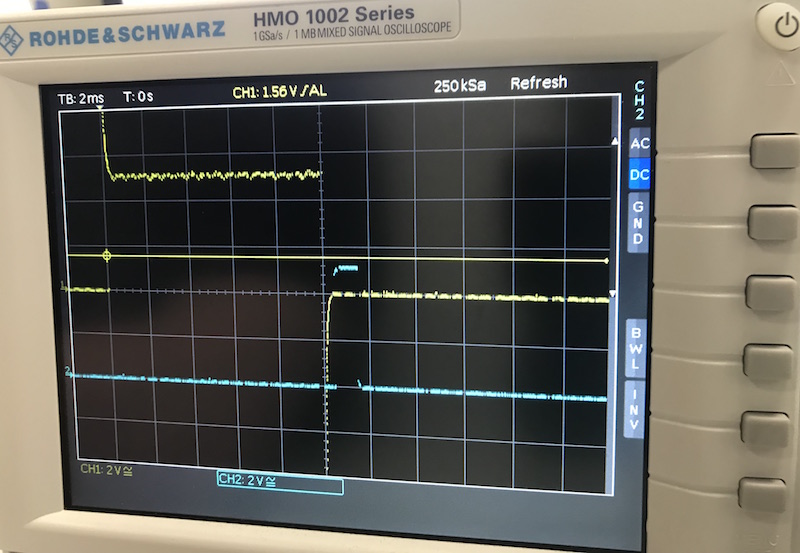
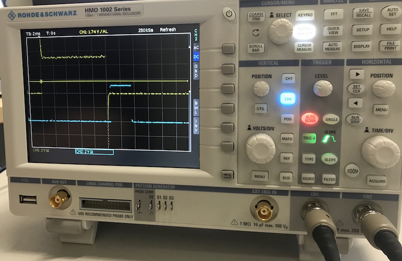
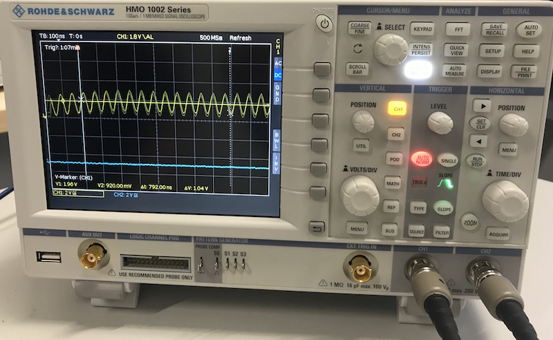
Since we want to display the data of our board and the sensor on an oscilloscope, below are a few pictures showing the data of the HC-SR04. I recorded the sensor values at different distances.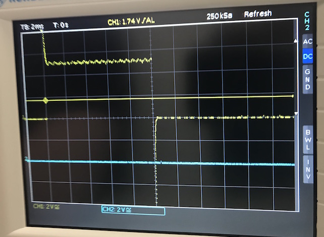
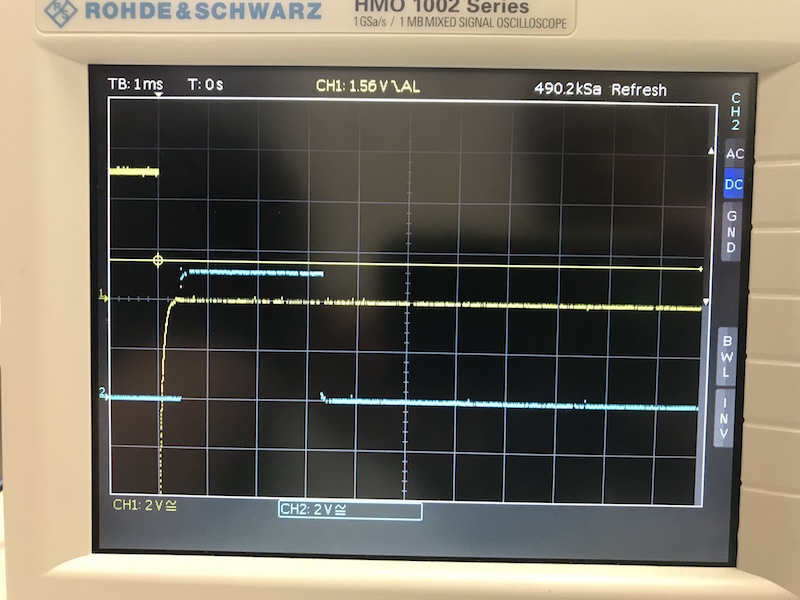
The following three images show different distances measured by the sensor.
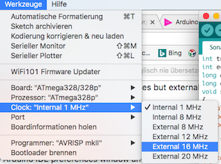
The following image and movie show a oscilloscope screen shots of the 16 MHz resonator, installed on my board.
Downloads
| Sonarsensor HC-SR04.ino | download |
| Hello HCSR04.py | download |