Week 6: Electronics Design
First of all I would like to express my sincere thanks to Aleksandra Konopek, my colleague who gave us tipp about this Eagle tutorial (german) Eagele Tutorial TU-Berlin. She supported me also by the documentation of this assignment.
Thanks to Tobias Poppe and Florian Paproth our instructors for their support in milling the PCB.
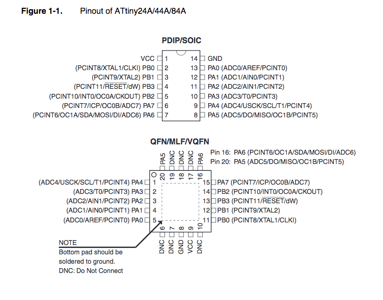
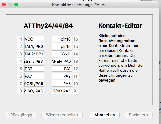
AtTiny44A Pinout
For electronics design we had to design and to mill a PCB as a "Hello World Board". We used ATtiny44A. You can see the pinout of this chip below:
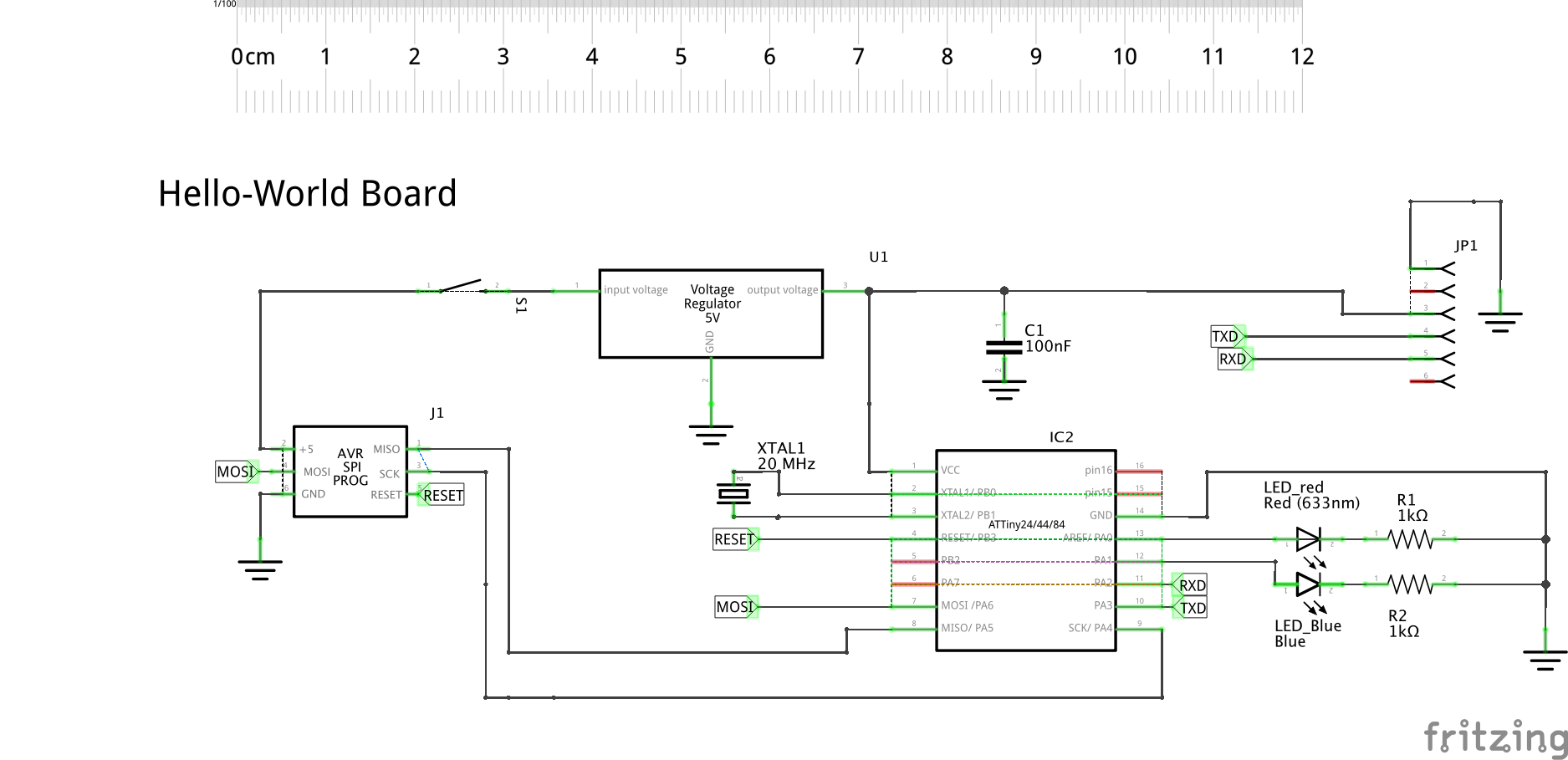
Hello Board Design Process
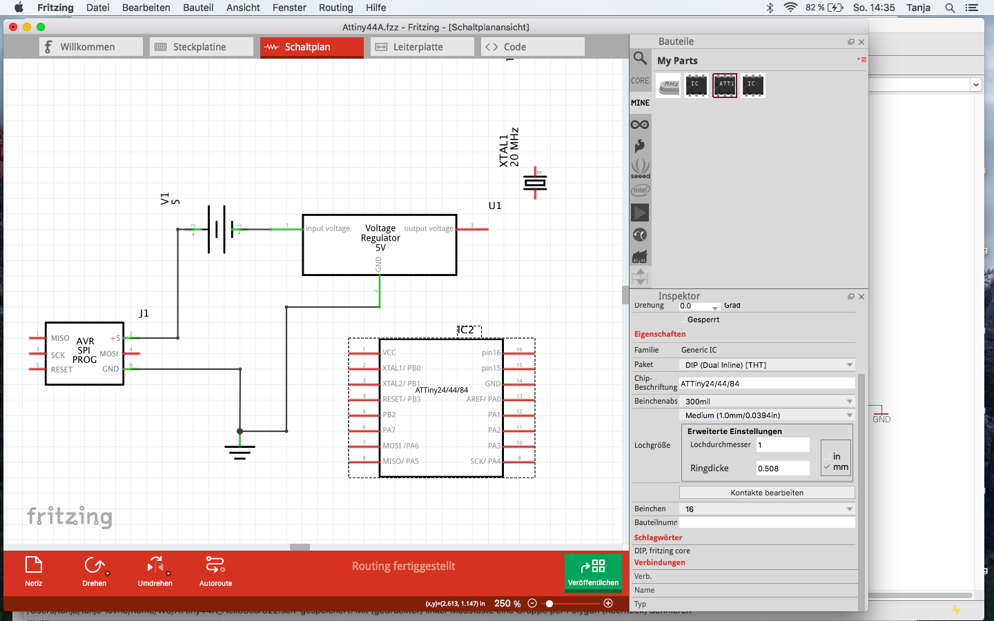
Below you can see my Hello World Board design using the software Eagle.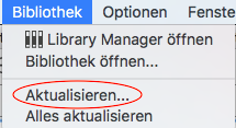
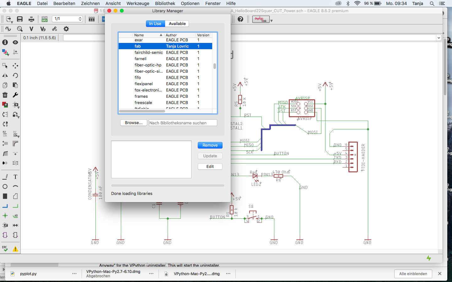
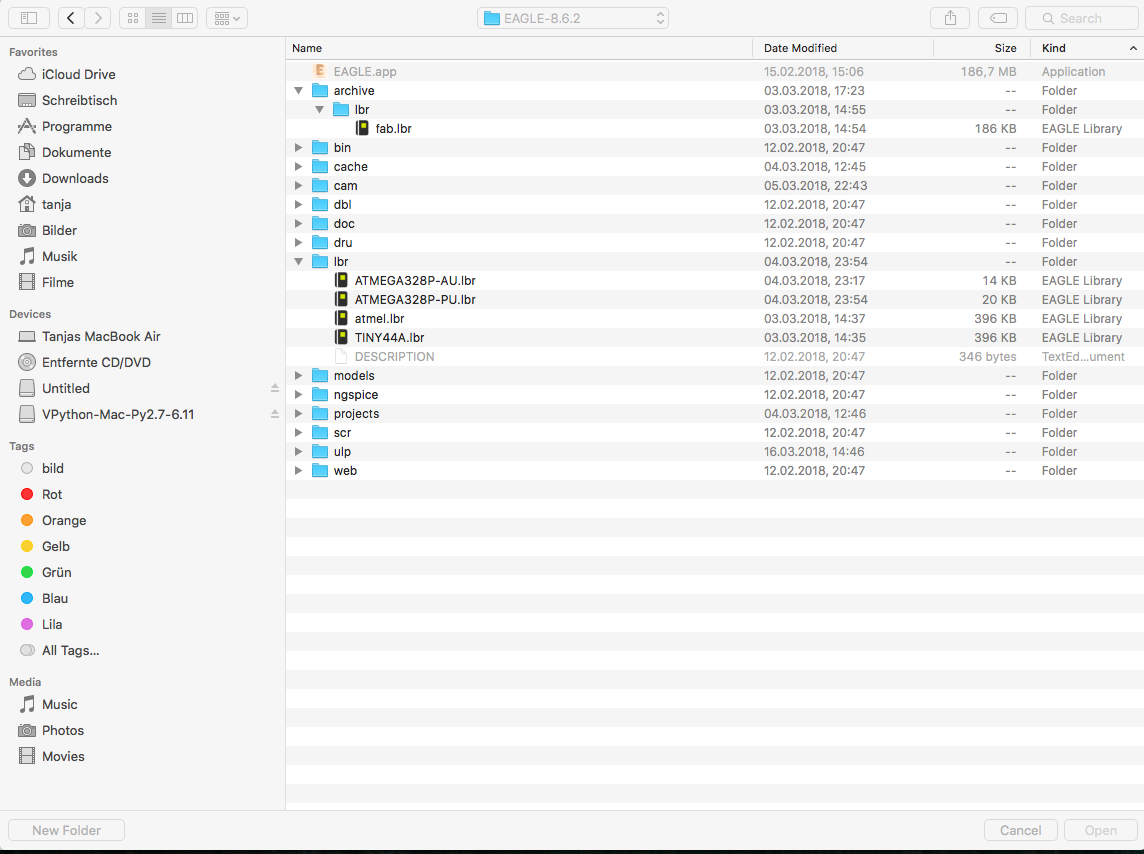
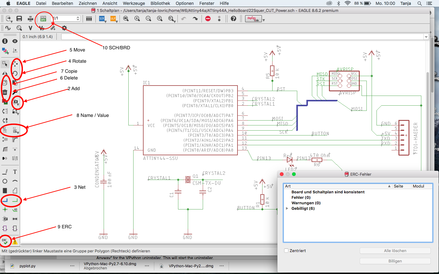
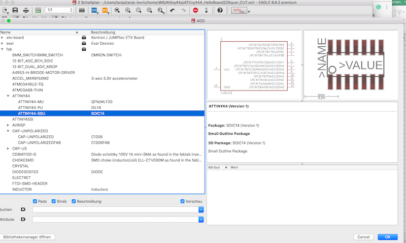
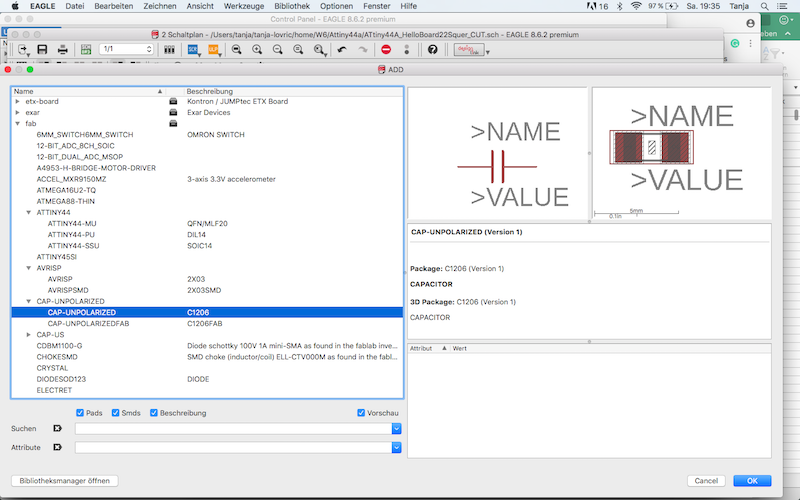
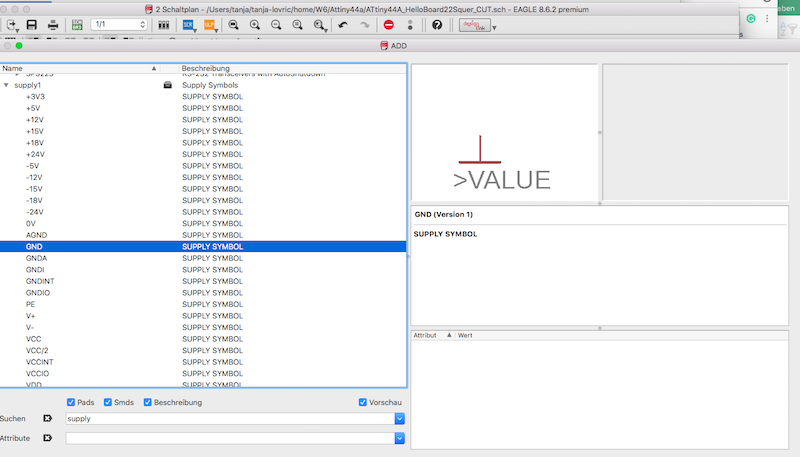
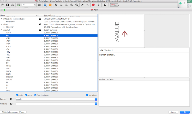
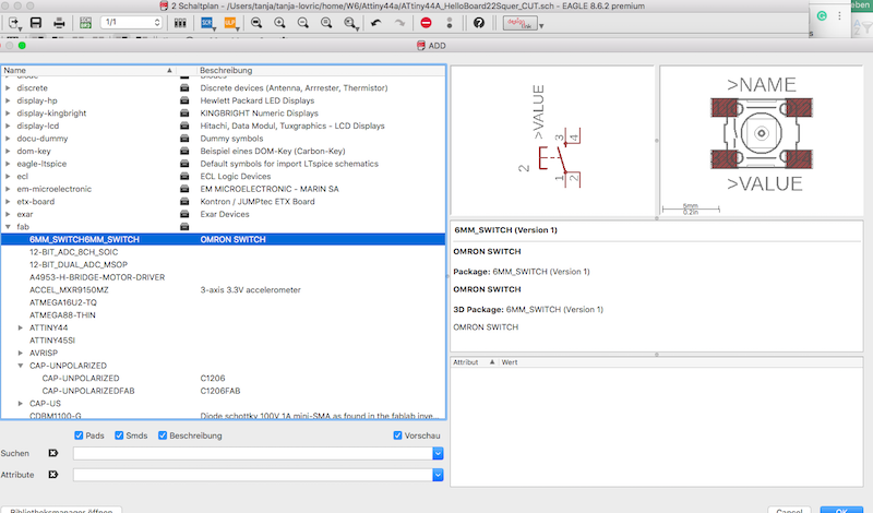
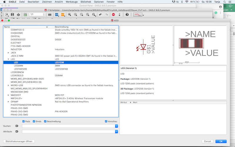
- After opening Eagle schematics I included the "fab" Fab Academy Library for footprints. For this I downloaded the "fab library" from the Fab Academys homepage and dropped "fab.lbr" in the folder "lbr".
After that I opened "Library Manager" submenue /Library pressed "Update" to load this library. Now the fab.lbr was ready to use. - First I had to get the components in the schematics I needed with the "add"-tool. Now the component is sticking to your cursor until you press the left mouse button.
- Then I had to wire using the tool "Net". For wiring you have to click the end points of the components to get them wired. To test if the component is hooked up to the element you should move it around.
- If you want to change the orientation of the component, you take "rotate" tool.
- If you want just to move the element you take the "move" tool.
- For deleting take the tool "delete".
- Copying with "copy" tool.
- If you want to change the name and the value of the wire or the component, you can use the tool "Name" and "Value".
- Bevore changing to the board design you should do the test of the wiring using tool "ERC" (electrical routing control).
- Now you can change to board layout design using the tool "SCH/BRD".
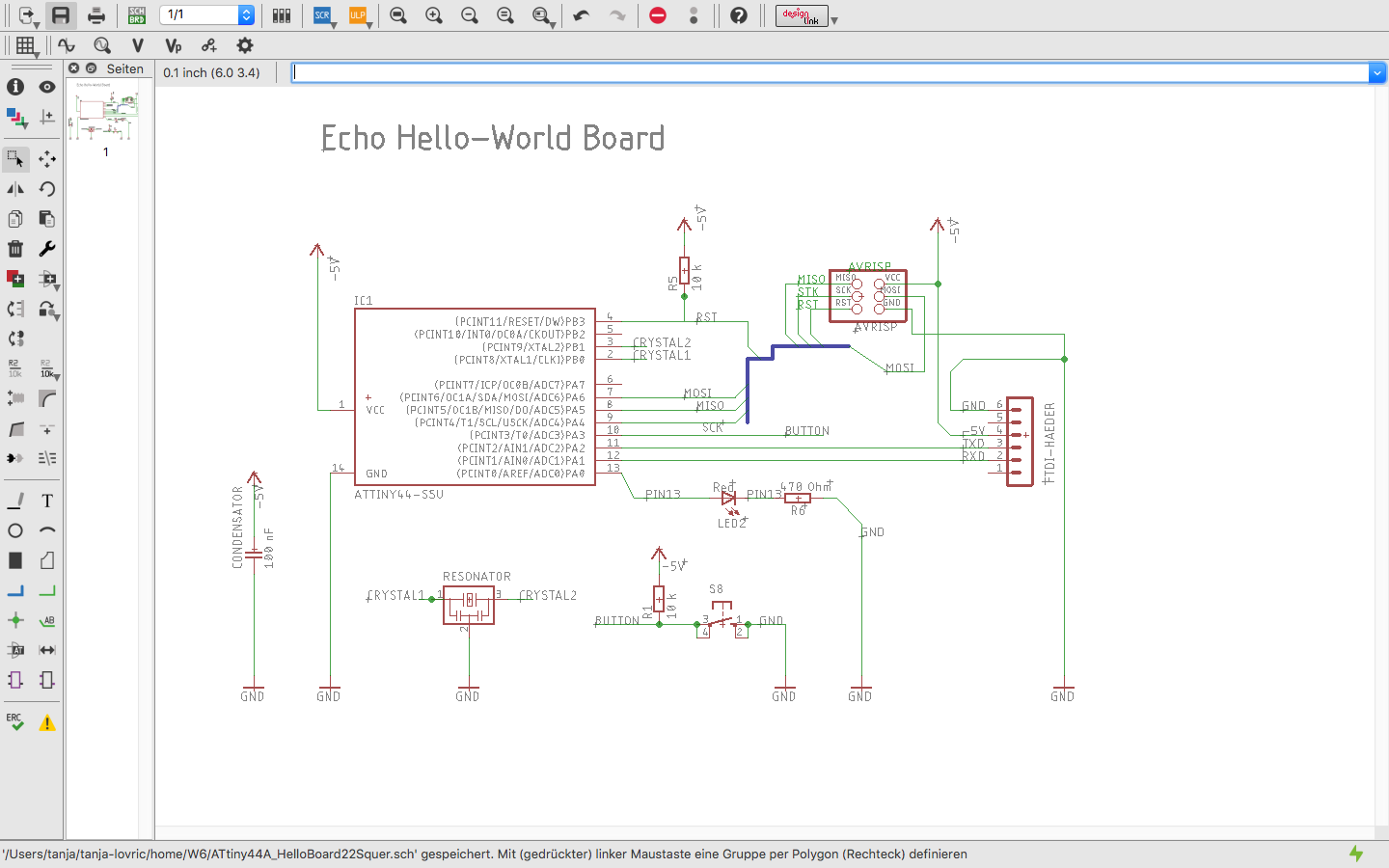
Below you can see the finished scheme.
Board Layout
- If you open the board layout view you will find all components mixed up in one corner. You have to move and arrange them into the rectangle space.
- The same as in the scheme menue you can move and rotate the elements here.
- After setting the componenets you will see a lot of straight yellow lines. They show the connections between the elments. They have to be routed using the tool "Route".
- To delete the wrong routes you can use the tool "Ripup".
- You can use "Ratsnest" to update the airwires. This helps you through routing prozess .
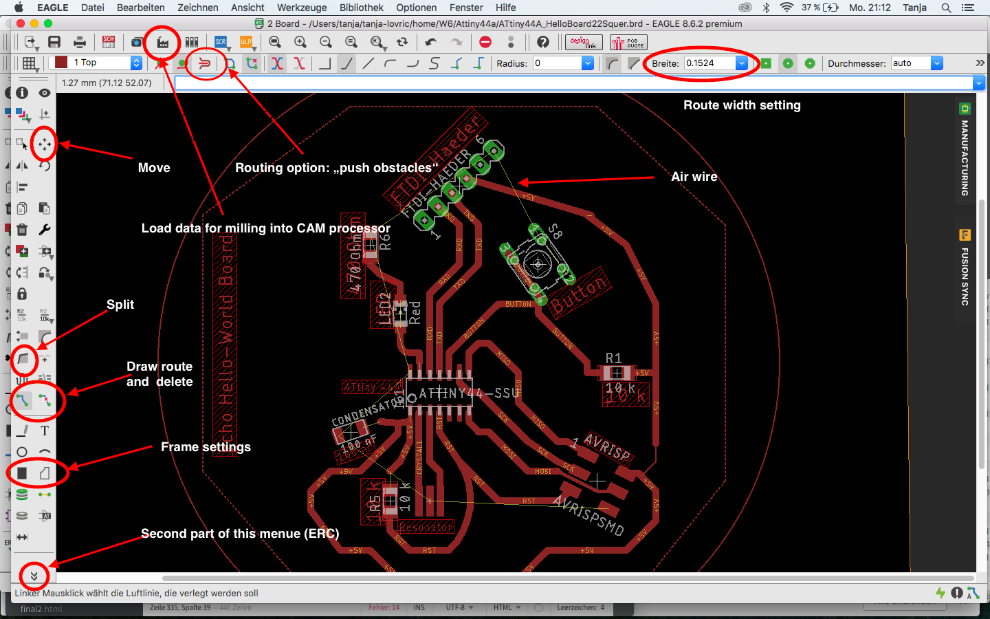
Above you can see the board layout tools which I commonly used for layout design.
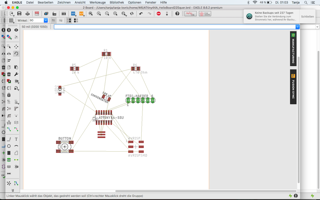
This is how the board layout of my Hello World Board looked like after switching from Eagle schematics ...
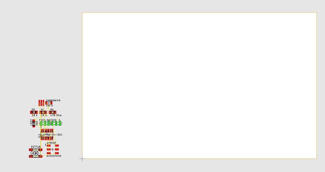
... as I pushed it to the rectangle where the elements are active ...
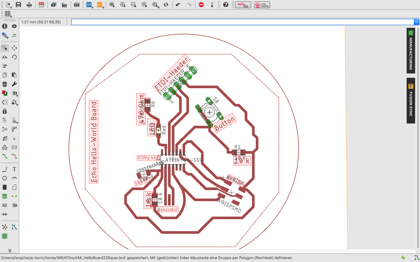
... and as it was finished.
Below you can find the Link to the list of the elements, which I used for design of my Hello World Board.
BOM Attiny 44A
Partlist ATtiny44A_HelloBoard22.sch exported from Eagle
| Part | Value | Device | Package | Description | MF | MPN | OC_FARNELL | OC_NEWARK |
| C2 | 100 uF | CAP-UNPOLARIZEDFAB | C1206FAB | |||||
| CRYISTAL | 20 MHz | CRYSTAL | 2-SMD-5X3MM | |||||
| IC1 | ATTINY44-SSU | ATTINY44-SSU | SOIC14 | |||||
| IC2 | REGULATORSOT23 | SOT23 | ||||||
| LED1 | Blue | LEDCHIPLED_1206 | CHIPLED_1206 | LED | ||||
| LED2 | Red | LEDCHIPLED_1206 | CHIPLED_1206 | LED | ||||
| R1 | 1 k | RES-US1206 | R1206 | Resistor (US Symbol) | ||||
| R2 | 1 k | RES-US1206 | R1206 | Resistor (US Symbol) | ||||
| S2 | 31-XX | B3F-31XX | OMRON SWITCH | B3F-3100 | 959704 | 36M3582 | ||
| U$1 | AVRISPSMD | AVRISPSMD | 2X03SMD | |||||
| U$5 | FTDI-SMD-HEADER | FTDI-SMD-HEADER | 1X06SMD |
Selecting the Footprints of the Components for Attiny 44A
Here you can find some information from ATtiny44A Datasheet
| Parameter Name | Value |
| Program Memory Type | Flash |
| Program Memory (KB) | 4 |
| CPU Speed (MIPS) | 20 |
| RAM Bytes | 256 |
| Data EEPROM (bytes) | 256 |
| Digital Communication Peripherals | 1-SPI, 1-I2C |
| Capture/Compare/PWM Peripherals | 1 Input Capture, 1 CCP, 4PWM |
| Timers | 1 x 8-bit, 1 x 16-bit |
| Comparators | 1 |
| Temperature Range (C) | -40 to 85 |
| Pin Count | 14 |
| Low Power | Yes |
| Program Memory Type | Flash |
| Program Memory (KB) | 4 |
| CPU Speed (MIPS) | 20 |
| RAM Bytes | 256 |
| Data EEPROM (bytes) | 256 |
| Digital Communication Peripherals | 1-SPI, 1-I2C |
| Capture/Compare/PWM Peripherals | 1 Input Capture, 1 CCP, 4PWM |
| Timers | 1 x 8-bit, 1 x 16-bit |
| Comparators | 1 |
| Temperature Range (C) | -40 to 85 |
| Operating Voltage Range (V) | 1.8 to 5.5 |
| Pin Count | 14 |
| Low Power | Yes |
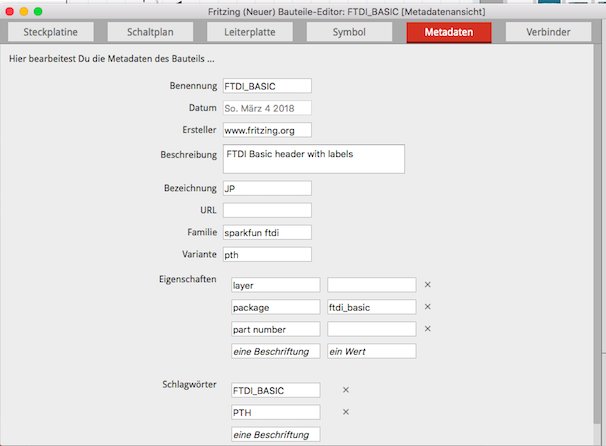
Fritzing App
Some more trials with the other tools like Fritzing.app (Fritzing.app Download). Installing Fritzing.app on Mac:Mac notes
Recent versions of OS X do not allow "unverified" software to be launched directly. In order to run Fritzing, you will need to either:
right-click the Fritzing icon and select "Open"
in the warning dialog, click "Open" or,
to get rid of the warning permanently:
go to the System Preferences open the Security and Privacy page
unlock it by clicking the lock in the lower left corner
set it to allow app downloads from anywhere.
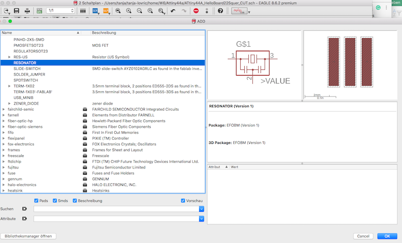
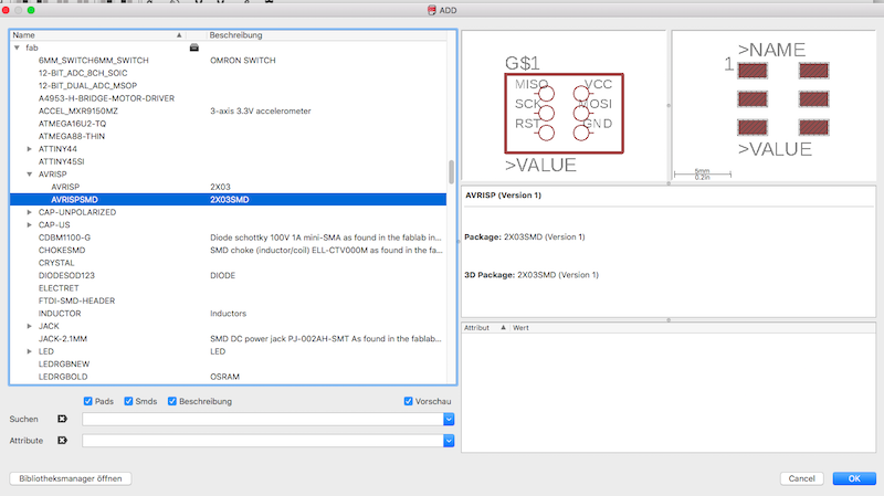
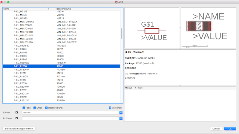
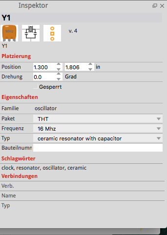
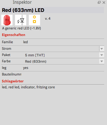
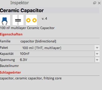
In the following you can see some menues and settings options from Fritzing.app for the elments I used for my board.
ATmega 328p-AU
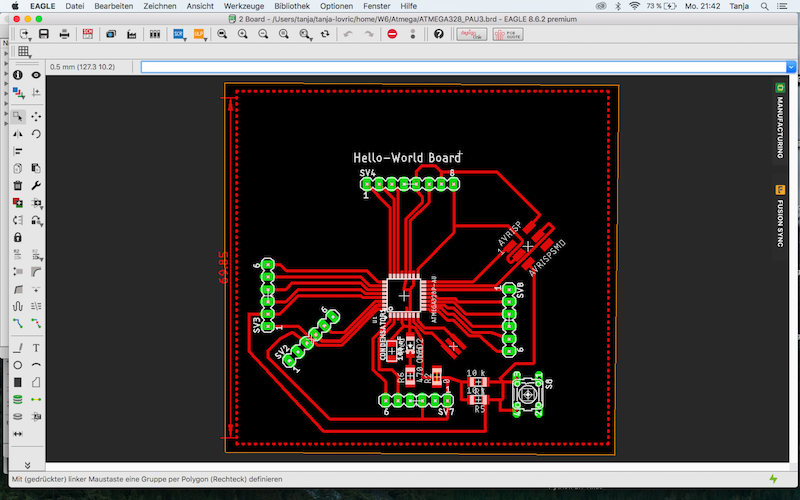
We were recommended from Tobias Poppe our instructor to produce the board with ATmega328p-AU because it would be much easier to use and it would give us more opportunities to hook up the sensors and actuators we choosed. So I did not use already finished design of ATtiny44A but made a new board schematics and board layout, which is to see in the following images.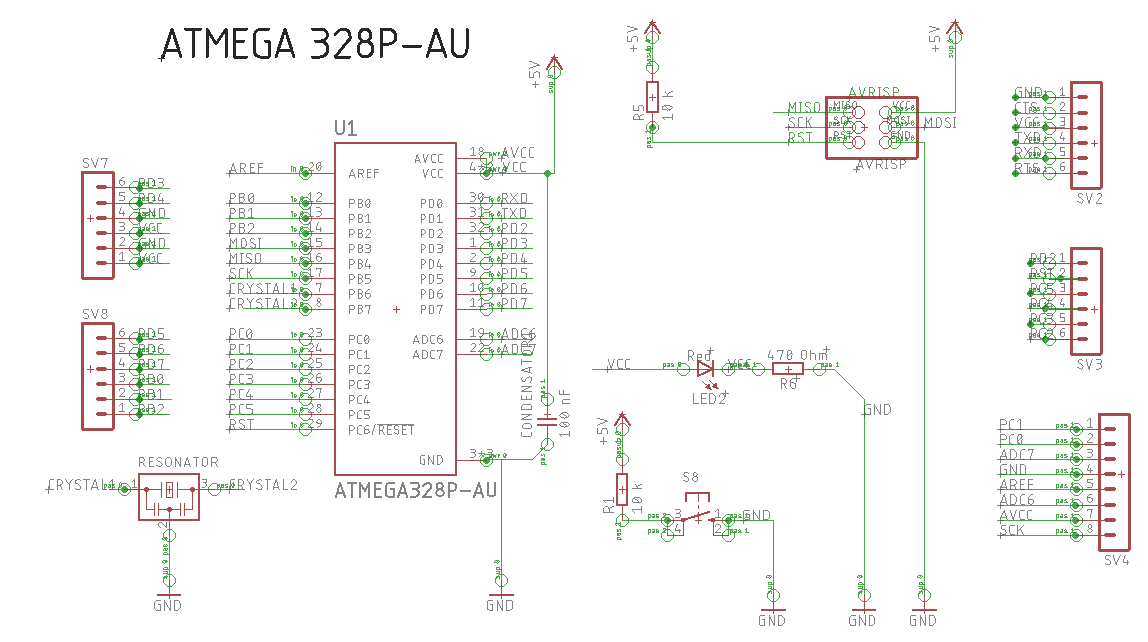
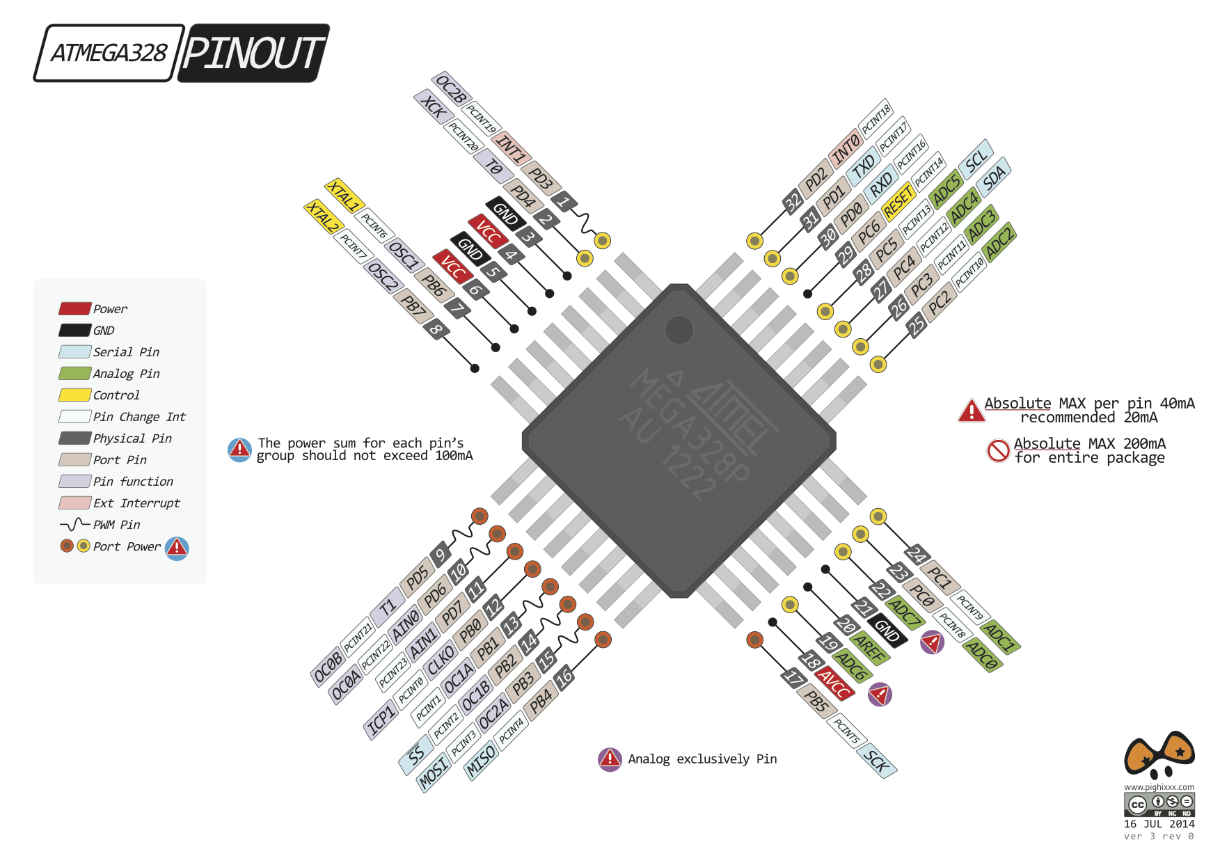
This image shows the pinout of ATmega328p-AU which I used for the orientation when labeling the pins in the schematics and also later when soldering them.
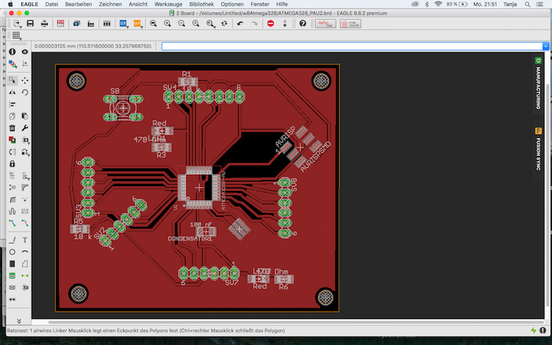
The following image shows the Board layout.
Here you can see the some areas which are black. Those are the areas on the PCB where the GND connection is missing.
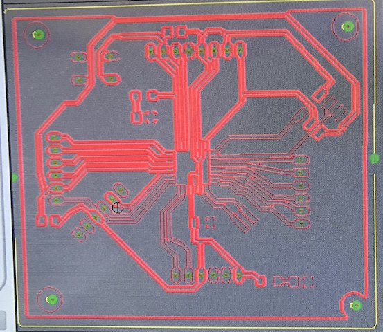
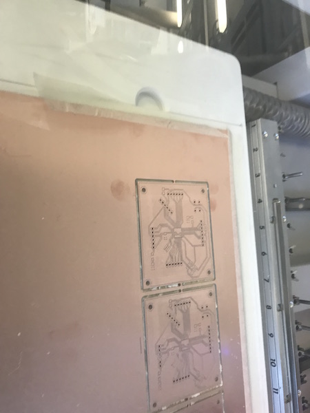
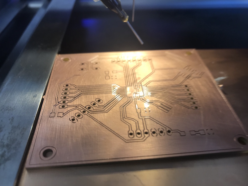
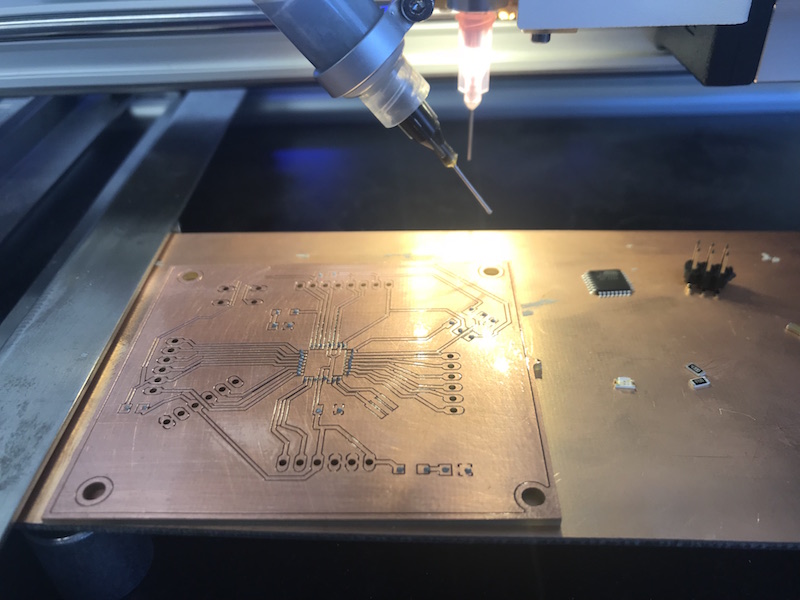
Following images show the process of milling and soldering the Hello World board on the LPKF Proto S63.
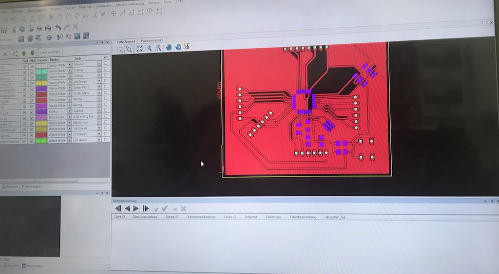
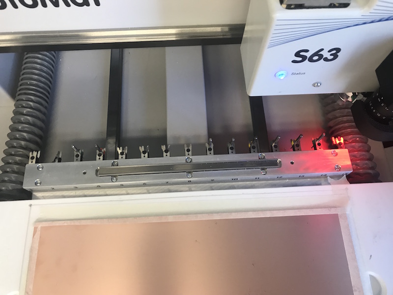
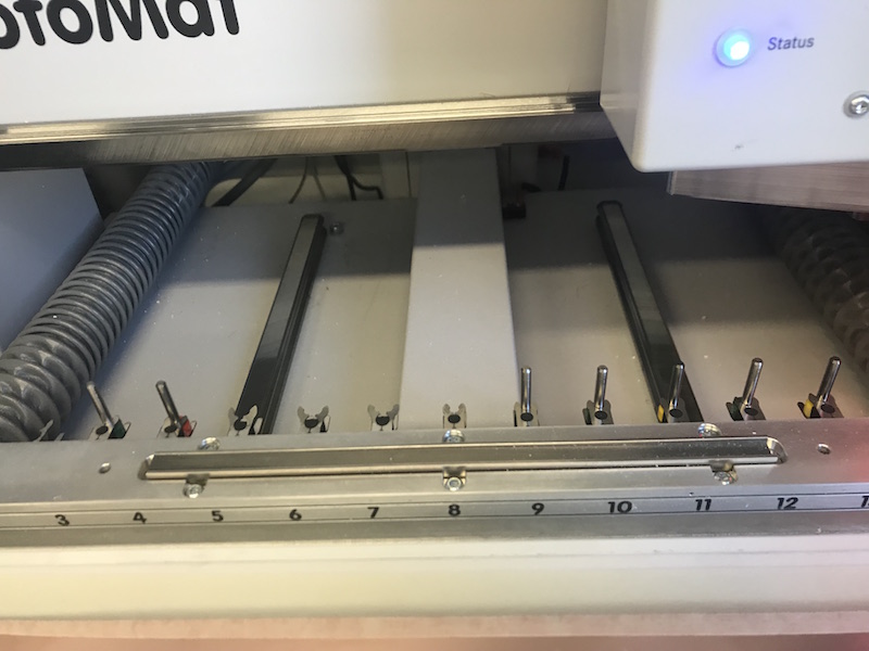
The following movie shows the the tool exchange at the beginning of the milling process:
The following images show the steps of finishing the PCB after the milling prozess:
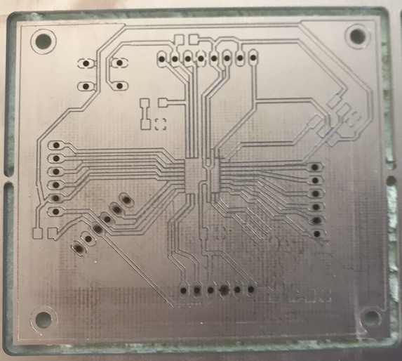
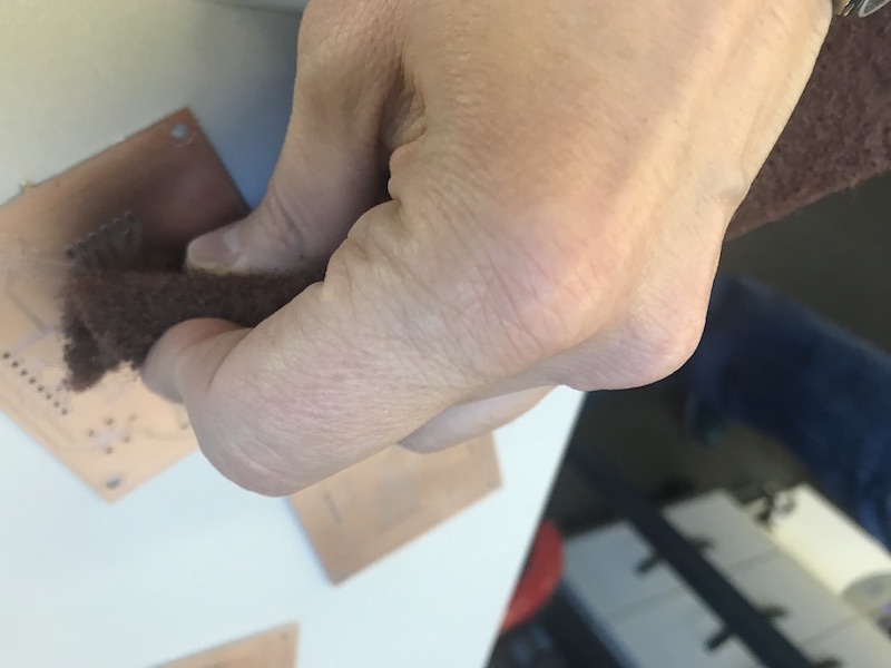
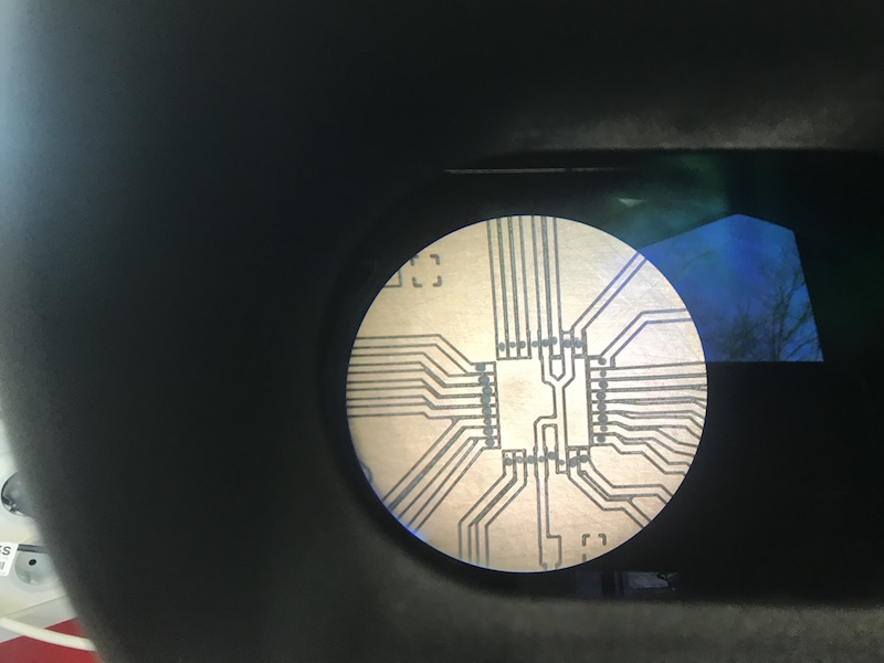
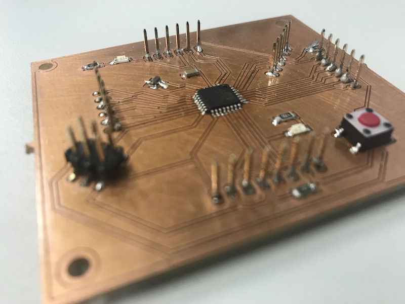
The following images show the view through the microscope at the footprint of ATmega328p-AU, soldering prozess and my finished Hello world Board:
Partlist exported from Eagle, ATMEGA328_PAU.sch
| Part | Value | Device | Package | Description | AVAILABILITY | DESCRIPTION | MF | MP | MPN | OC_FARNELL | OC_NEWARK | PACKAGE | PRICE |
| AVRISP | AVRISPSMD | AVRISPSMD | 2X03SMD | ||||||||||
| CONDENSATOR1 | 100 nF | CAP-UNPOLARIZEDFAB | C1206FAB | ||||||||||
| LED2 | Red | LEDCHIPLED_1206 | CHIPLED_1206 | LED | |||||||||
| R1 | 10 k | R-EU_R1206 | R1206 | RESISTOR, European symbol | |||||||||
| R5 | 10 k | R-EU_R1206 | R1206 | RESISTOR, European symbol | |||||||||
| R6 | 470 Ohm | R-EU_R1206 | R1206 | RESISTOR, European symbol | |||||||||
| RESONATOR | RESONATOR | EFOBM | |||||||||||
| S8 | 10-XX | B3F-10XX | OMRON SWITCH | B3F-1000 | 176432 | 36M3542 | |||||||
| SV2 | MA06-1 | MA06-1 | PIN HEADER | unknown | unknown | ||||||||
| SV3 | MA06-1 | MA06-1 | PIN HEADER | unknown | unknown | ||||||||
| SV4 | MA08-1 | MA08-1 | PIN HEADER | unknown | unknown | ||||||||
| SV7 | MA06-1 | MA06-1 | PIN HEADER | unknown | unknown | ||||||||
| SV8 | MA06-1 | MA06-1 | PIN HEADER | unknown | unknown | ||||||||
| U1 | ATMEGA328P-AU | ATMEGA328P-AU | QFP80P900X900X120-32N | ATmega Series 20 MHz 32 KB Flash 2 KB SRAM 8-Bit Microcontroller - TQFP-32 | Good | ATmega Series 20 MHz 32 KB Flash 2 KB SRAM 8-Bit Microcontroller - TQFP-32 | Atmel | ATMEGA328P-AU | TQFP-32 Atmel | 2.38 USD |
Downloads of the Eagle Schematics and Partlists
| Eagle shematics of ATmega328p-AU | Download Eagle shematics ATmega328p-AU |
| Eagle shematics of ATtiny44A (zip) | Download Eagle shematics and board layout of ATtiny44A round test |
| Partlist ATtiny44A | Download |
| ATtiny_Fritzing.fzz | Download wiring shema of ATtiny44A using Fritzing.app |