Week 9: Molding and Casting (Draft)
First off all I would like to thank my collegue from FabLab Kamp-Lintfort
Ahmed Bilal for great support again in this week and using the milling mashine in their lab. Many thanks also to Aleksandra Konopek my colegue in Bottrop for many helpfull tipps and ideas and her support in this week.
Many thank also to Florian Papproth, our instructor for Tipss in using Fusion 360 CAM Settings.
For this week assignement there were many steps to go:
Folowing materias are needed:
Group Assignement: Studying of the Safety Data Sheets and Simple Cast Tests
We used the following material in Bottrop to mill the mold: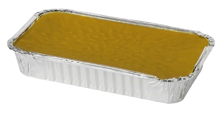
Regina casting wax
Regina casting wax safety data sheet
As the main component of Regina wax is paraffin / stearin mix, its fermentation level is very low. It is very easy to cut because of course wax has very low hardness. You should be careful when cleaning the mold, because you can form contours very quickly with too much pressure. By remelting the chips, we can use the wax mold again. As a result, wax is a very suitable material for this application and also sustainable in use.
This is the silicone I have choosen for the negativ form:
The manufacturer of the silicone rubber is
AOS-UG.com
It is a food grade approved silicone so I do not expect any hazardous ingredients in it.
I wrote to the manufacturer because of the data sheet and still wait for a response.
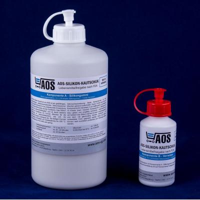
AOS Silicone rubber molding compound.
On his homepage, the manufacturer has given the information on the evidence of the safety of the silicone:
"This product has been extensively standardized by several independent laboratories
FDA CFR 177.2600
EC 1935/2004 and
EU 10/2011
testet and was approved for use with fatty and aqueous foods depending on the product variant."
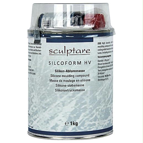
The other silicone I used is Silicoform HV Boesner. The accompanying safety data sheet is here to find.
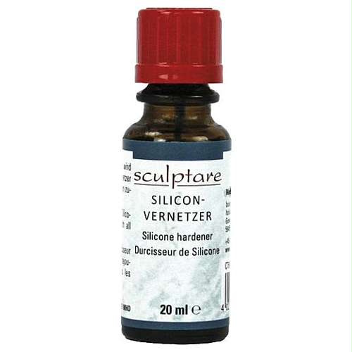
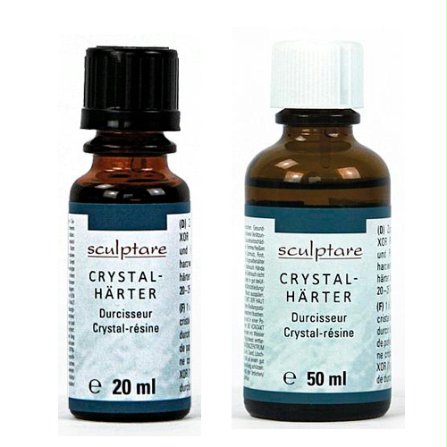
The second component required is the Hardener or curing ironer.
The SDS for the hardener can be found here .
Since the required crosslinker contains highly hazardous substances, the mixture should be stirred under high safety precautions. It should best be used exhaust ventilation and protection gloves. Skin contact with the mixture should be avoided. It still remains open the question of whether the crosslinker is necessary or whether the silicone would cure even without the hardener after a long time.
First I wanted to use the following casting resin from Boesner, as we had some of it in the FabLab:
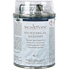


Resin, Boesner Online Shop
Product Inormation from provider:
"Brilliant, crystal clear polyester resin for the production of highly transparent resin blocks." The casting resin is used in combination with glass fiber and glass fiber chips With resin tinting paint, polyester glass casting resin can be cast in a single casting in layer thicknesses up to 15 mm (minimum thickness 4-5 mm) be dyed either opaque or transparent, including product information and application instructions.
Technical characteristics:
Density according to DIN 53217: 1.12 g / m³
Viscosity at 20 ° C according to DIN 53015: 930 mPa · s
Breaking index at 20 ° C according to DIN 53491: 1.52
Impact strength according to DIN 53453: 8 kp / m²
Heat resistance according to DIN 4458: 52 ° C
Dielectric constant according to DIN 43483: 3.00 V
Hazard Statement: Harmful Xn, Corrosive, Extremely flammable
Statements
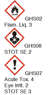
Resin: danger! Flammable liquid and vapor. Causes skin irritation. Causes serious eye irritation. Of course, it can affect fertility or harm the unborn child. The exhibition on prolonged or repeated exposure. Hazard pictogram: GHS02, GHS07, GHS08 *
Hardener: Danger! Heating can exploit fire. Harmful if swallowed or if inhaled. Causes serious irritation of the skin and serious eye damage. Hazard pictogram: GHS02, GHS05, GHS07 *"
The safety data sheet can be found here:
Resin hardener,
hardener SDS:
www.boesner.com , Boesner
I also wanted to test plaster whose SDS can be found here:

Modulan Modelliergips
SDS Modulan Modelliergips, Hornbach
Below are excerpts from the safety data sheet
Name of substance: calcium sulfate hemihydrate
Chemical name: calcium sulfate
Formula: CaSO4 * 0.5H2O
Synonyms: ground natural gypsum, sulfuric lime
Regulation (EC) No 1272/2008 The substance is not classified as dangerous
[The product is in accordance with CLP regulation
not rated]
2.2 Label elements
Labeling according to Regulation (EC) No
1272/2208: not applicable
Hazard pictograms: none
Signal word: none
Hazard warnings: none
Safety instructions: none
4.1 Description of first aid measures
General information: No adverse effects on intended use of the
Substance.
After inhalation: Fresh air supply, consult doctor in case of complaints.
After skin contact: Wash off with soap and water.
After eye contact: Eyes open for at least 15 minutes with the eyelid open
Rinse water and consult an ophthalmologist.
Ingestion: Rinse mouth and drink plenty of water.
medical
Administer treatment.
Information for the doctor: Skin-friendly neutral salt. No allergic reactions known.
Soluble dust.
Section 6: Accidental Release Measures
6.1 Personal precautions, protective equipment and in case of emergency
method to be used
Not for emergency trained personnel and
Emergency responders:
Ensure adequate ventilation.
Wear suitable personal protective equipment.
Avoid dust formation.
Product forms slippery surfaces with water.
6.2 Environmental precautions
No special environmental measures required.
Section 7: Handling and Storage
7.1 Precautions for safe handling
Protective measures: Avoid dust formation and eye contact
Fire protection measures: The product itself does not burn. No special measures
required.
Measures to prevent
of aerosol and dust formation:
If technically possible devices with local exhaust
use.
Notes on the general
Industrial hygiene:
Do not eat, drink, smoke or runny nose at work.
Wash hands before breaks and work.
Use work clothes should not be outside of
Work area to be worn.
However, because of the pollutants, I decided against it and used wax and plaster for the casting.
Simple Cast Tests
AOS Silicone Test
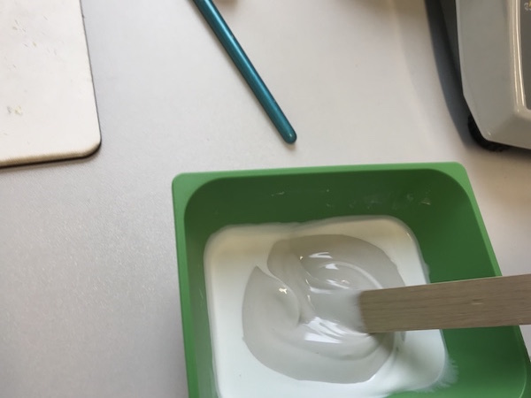
For the preparation of the mixture, both components of the silicone rubber (A) and crosslinker (B) are weighed and mixed in a mixing ratio of 10: 1. The silicone mass is poured slowly into the mold.
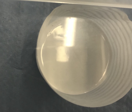
The silicone mass had already shown clear signs of curing after one hour (at about 21 ° C room temperature):
I have a simple form in a shell to test the curing of the silicone at a higher thickness and to see how big is the gas bubble formation without the use of the vacuum box.
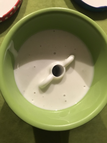
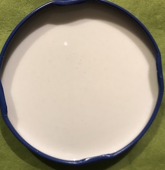
As you can see, some gas bubbles have remained on the surface.
Silcoform HV (Boesener) Silicone Test
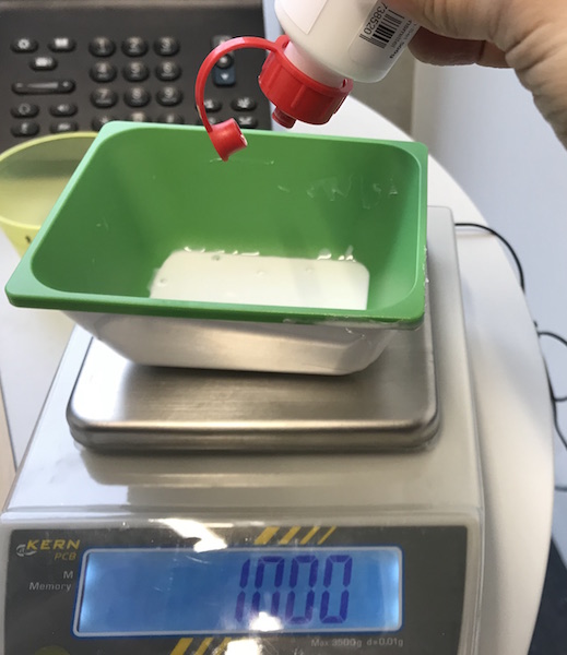
I have mixed a small sample of 10g silicone and 2% hardener before filling the actual mold. I put into the DIY vacuum box to see if it works:Some small bubbles have risen to the surface within 5 minutes of waiting time. That was the proof that the vacuum box produced a certain negative pressure. How big the pressure difference was we could not measure.
This mixture has not been cured after 24 hours. For the mixture, I used the information on the weight of a drop and added 8 drops for a 2% mixture.
Design of the Mold
Originally, I had thought of hollowing the cone of thieves and placing an LED in the solar trough for the display of indoor air quality. This would have been possible with another narrower cone, which I should have placed in the larger cone for casting. Aleksandra had recommended that I insert the LED into the mold and make only one well with an object.
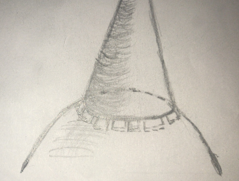
I liked the idea because it was a simpler solution than hollowing the body. The contacts of the LED I would be relatively easy to lead out and connect to the board via a resistor (see the following figure).
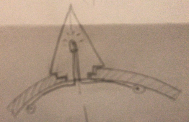
Since I will fill in the liquid silicone cast later through the bottom of the cone, the air bubbles that may be trapped in the cast will have enough space to escape. If I only had a narrow filler hole, I would also have to think of a vent because the air bubbles could not struggle through the filling hole against the pressure of the filling material.
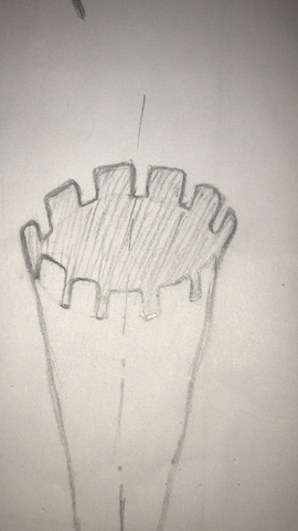
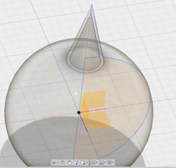
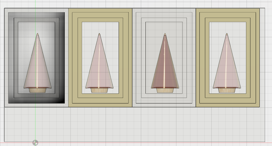
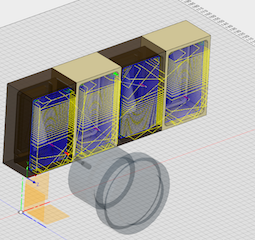
It should be noted that you need a form that consists of two parts, which should later fit exactly on each other. First, I created a 3D drawing of a sunray and devided it using "Devide Bodies"
into two symmetrical (mirror-inverted) parts. Each of these two parts, together with the other, should act as a container for the silicone after milling and form a hollow mold (negative mold).
Since the ray of sunshine is supposed to be part of the finale, it must be inserted into the solar body and hold firmly in it. For this I have created a cylindric close to the bottom of the cone. Furthermore, I have made the sheath of the cone slightly wider than the cylindrical end so that the cone can stand in the correct position.
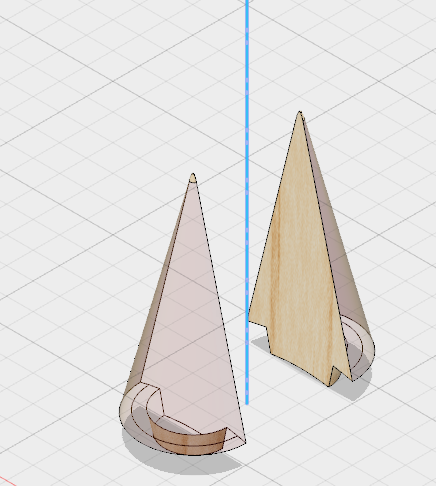
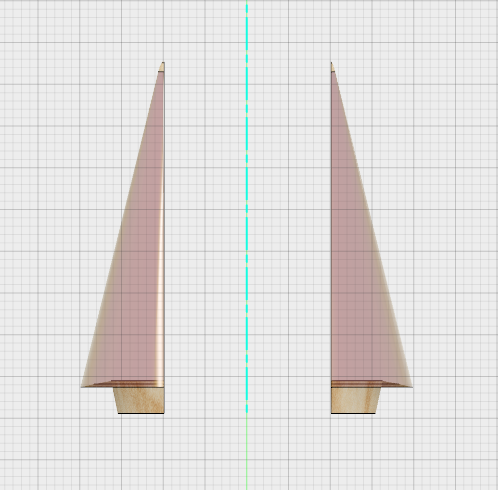
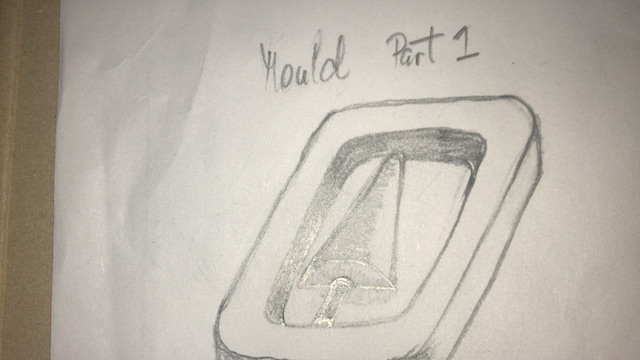
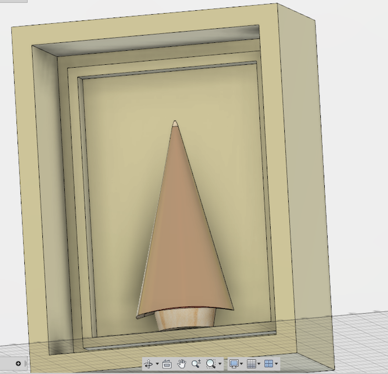
In order for the liquid silicone to stay in position, every half of the 3D shape gets a frame. In addition, I have drawn a second frame (tongue and groove), which should ensure the exact position of the two halves of the shape.
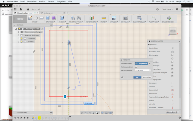
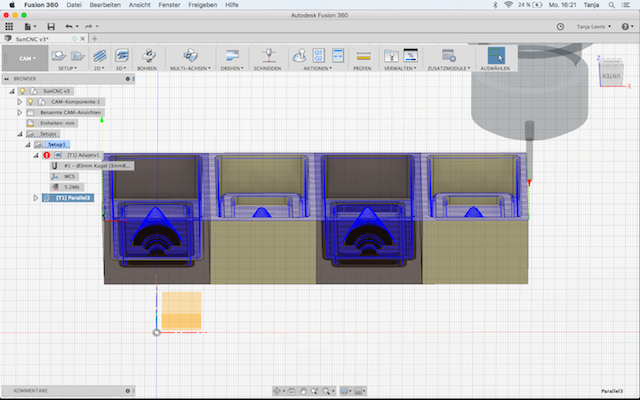
Milling the Mold
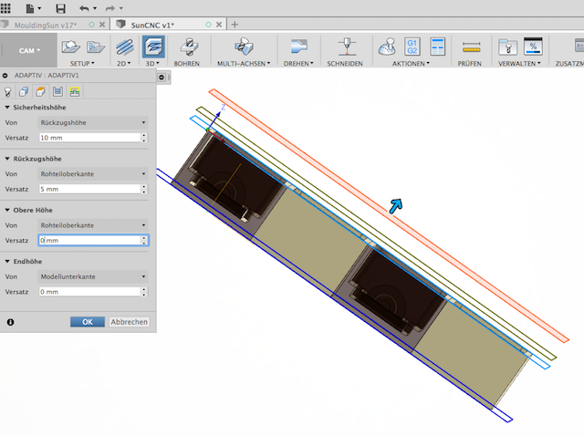
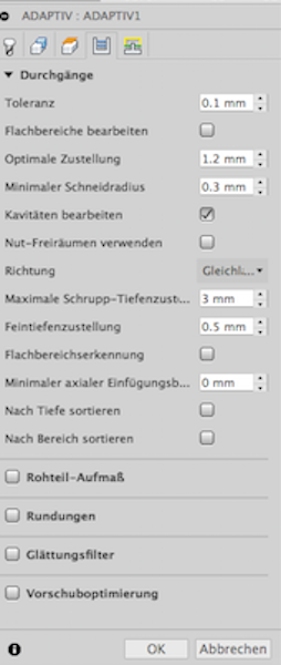
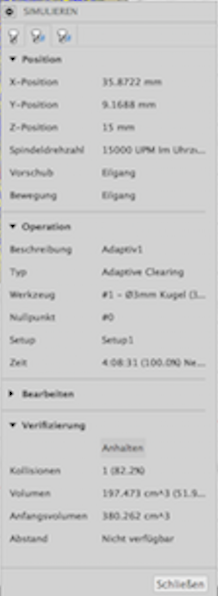
In order to be able to mill the shape, it was necessary to simulate the 3D drawing in Fusion360 in the CAM mode of the same software. I have made the following settings:
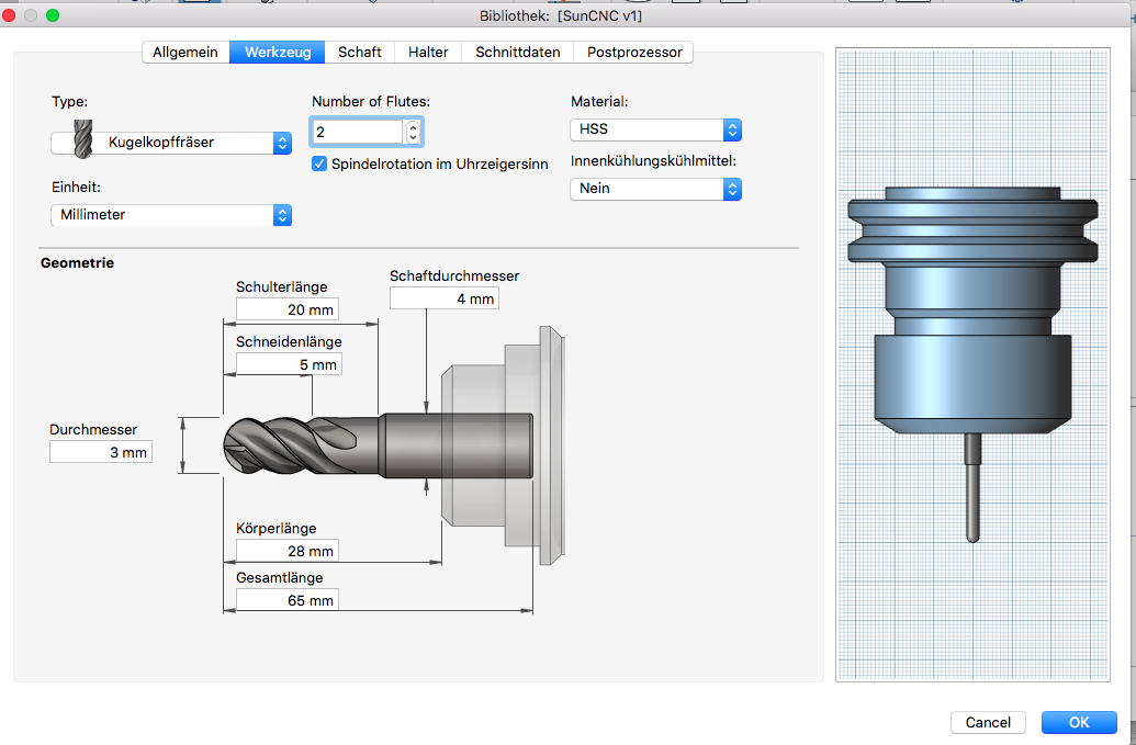
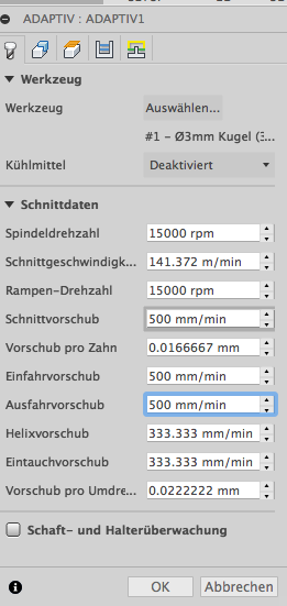
For the milling of the mold from which the negative mold is shown later, it is best to use wax. There are different types of wax, but we had opted for beeswax (paraffin / stearin mixture 80%: 20%). More details about the material and SDS can be found above in the document describing the materials used.
For the shape we have the following block paraffin/ stearin wax block 80/20: Boesner Shop
used with dimensions: Wax box size
----------------------
185 mm length
95 mm width
30 mm height
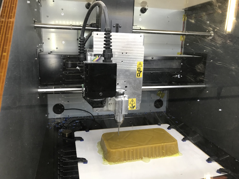
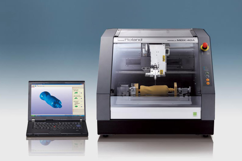
Unfortunately, I did not notice in the calculation that the surface of the shape is not flat. This will only become apparent later after the mold has been finished with some errors in the back wall. Since our milling machine in Bottrop is currently not working, I was able to use the following milling machine in the friendly FabLab at Rhein Waal University in Kamp-Linfort (thank you very much for that): Roland MDX-40A
There was not anything special regarding the handling of the material to consider except that the room should have sufficient air exchange. However, this was an indication that the material is not completely harmless even if there were no warnings in the safety data sheet as Niel Gershenfeld, told us in the lecture.
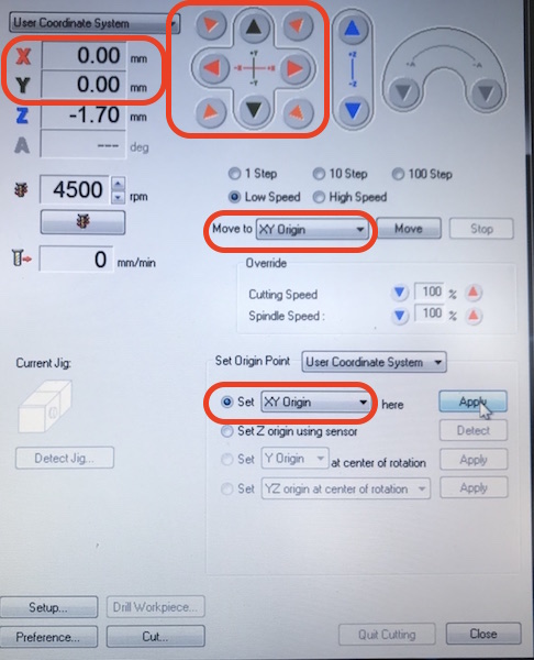
Settings of the Milling Machine.
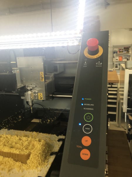
First, the xy plane must be set to a starting point (x, y) = (0,0). Here I have set the milling head in the lower left corner of the factory. For this I pressed arrows on the graphical user interface in the appropriate direction. Subsequently, I have printed the xy Origin button to tell the CNC milling machine that will be the zero point for the x-y plane. The same thing I did for the Z-direction.
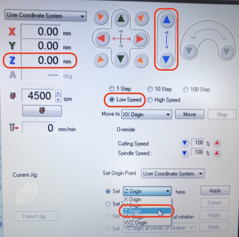
Settings of the Milling Machine.
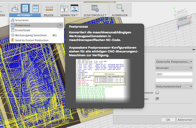
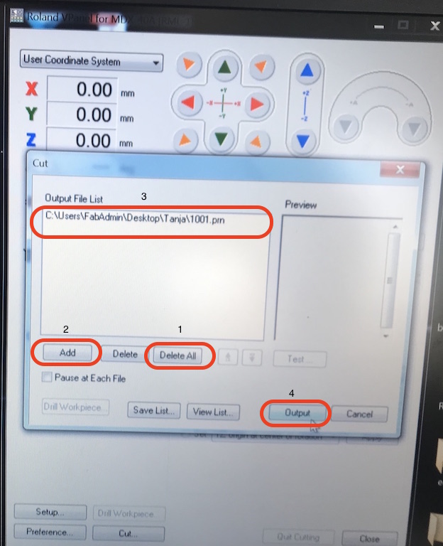
After setting the zero point, the file containing the G-code for the milling job can be loaded. Before, old files should be deleted from this window. Finally, to start the router, press the "Output" button.
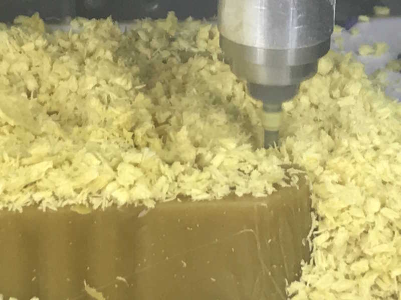
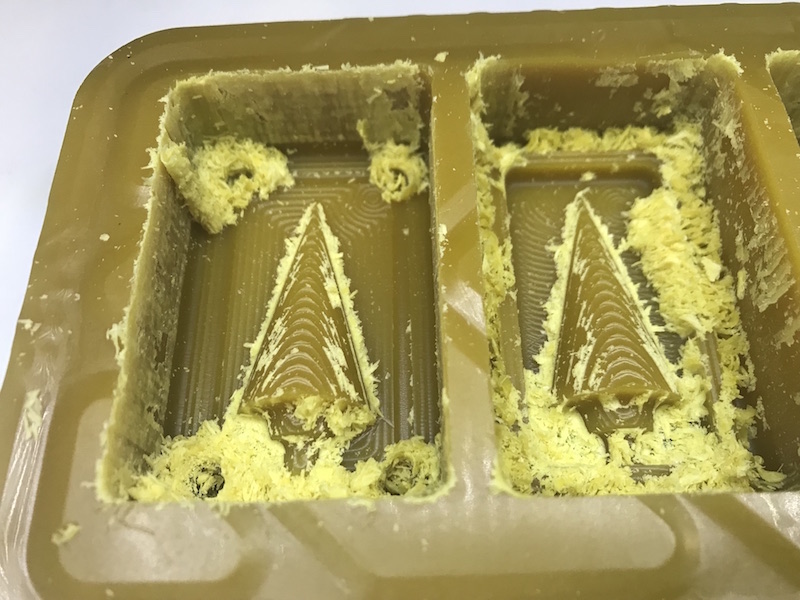
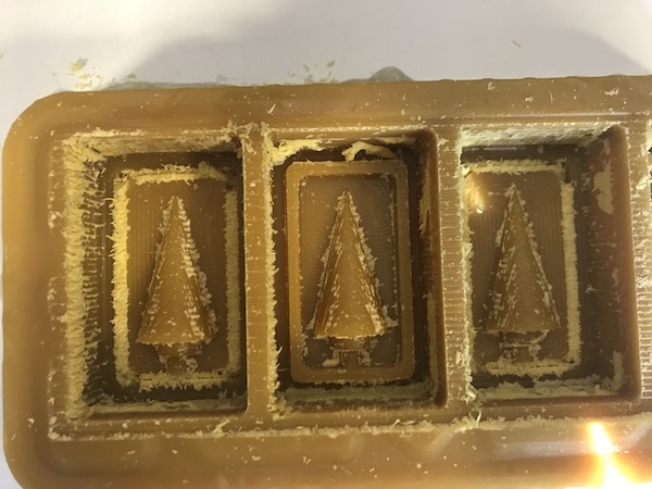
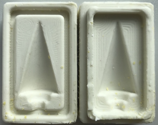
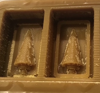
After the first round the waxbolt looked like this:
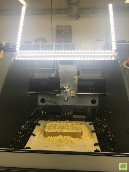
In the images it can be seen that at certain places of the form much of the chips have remained stuck. For this reason, when milling with this very heat-sensitive wax, you should vacuum the chips more often so that it does not clump due to the pressure of the milling head and the heat generated. The following figure shows that in the third box a strip is missing in the back wall. This was caused by the fact that after the milling process I wanted to free the form from the chips and tried this with compressed air. Since the chips in the narrow columns could not be removed with a brush, I tried the compressed air, which had then made it, but had also printed out the back wall in that thin spot with.
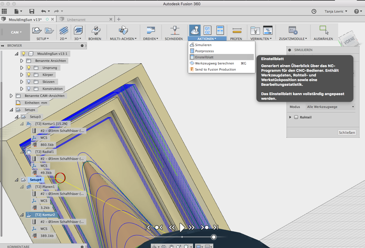
Two further milling passes were necessary. The second I did with the same Milling Tool but with the following settings:
I did the third round with another 1.2mm diameter tool:

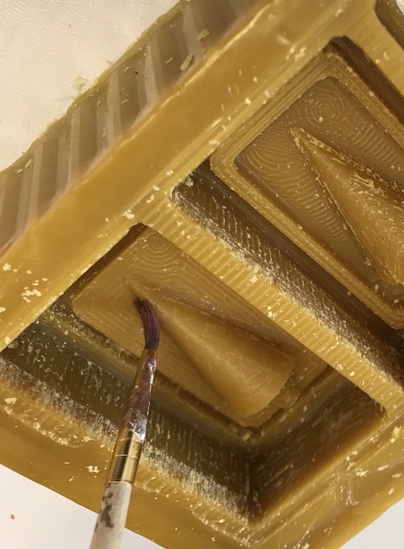
After milling, some spots in the mold were not clean, so these disturbing areas had to be removed very carefully with a brush and sandpaper.
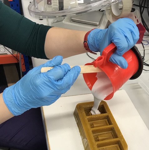
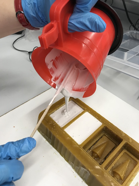
Casting the Negativ Form
When mixing for the mold, I weighed 2% of the hardener in relation to the silicone. I mixed a total of 130 g of the Silicororm HV and 2.6 g of the hardener. This mixture was then cured after 24 hours.
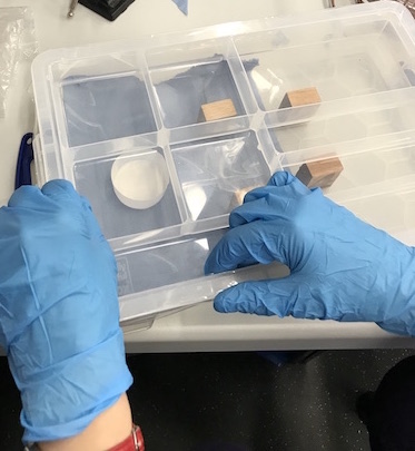
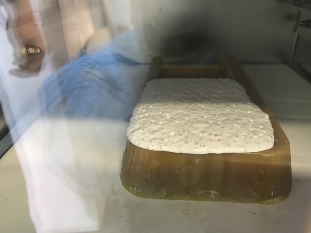
I had put a sample in one of Aleksandra's with a vacuum pump and a sealed storage box vacuum box to let the gas bubbles escape. Some gas bubbles escaped, as we did not know how much pressure difference was in this DYI vacuum cabinet, I put the actual mold later in a laboratory vacuum cabinet (see following image).
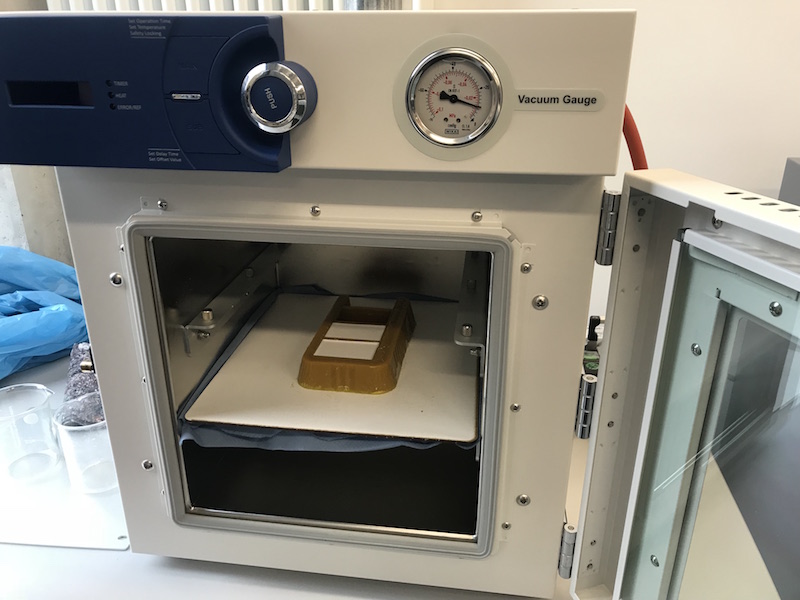
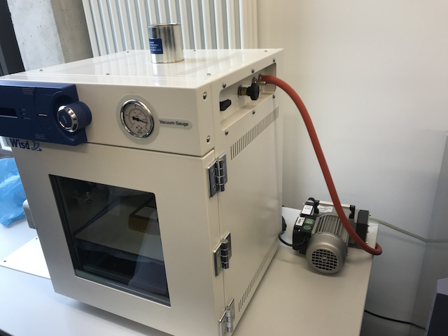
Due to the large pressure difference, many gas bubbles have risen on the surface of the casting. The volume of the silicone mixture has increased so much that the mass has overflowed over the edge of the mold. We attenuated a wooden board and paper under it. After the pressure has been restored to the atmospheric pressure, all bubbles have disappeared.
After hardening the layer in the mold on the next day, I noticed that the thin layer, which had overflowed over the edge of the mold in the vacuum cabinet, has not hardened so well as the thick layer.
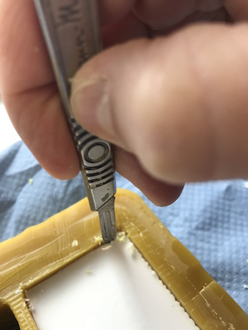
With a scalpel, I cut off the superfluous layers of silicone and carefully cut out the hardened mass from the mold along the edges. It is difficult to not cut in the form itself because the wax has very fair hardness.
After all sides of the hardened silicone mold were separated from the wax mold, with the help of Aleksandra I was able to push up the mold and remove it.
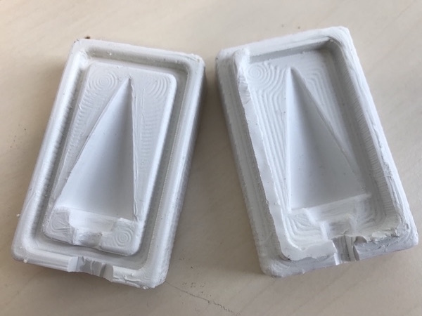
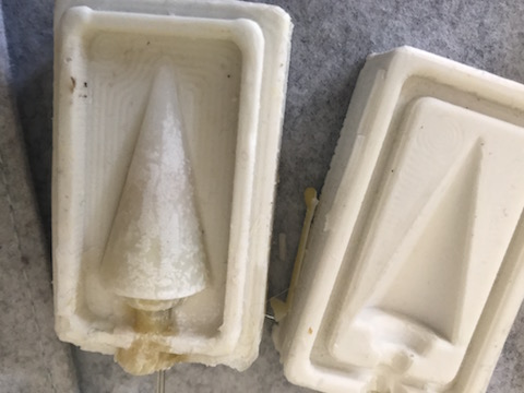
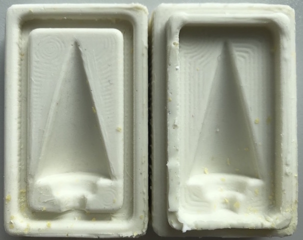
The shape had adapted very well to the milled shape of the sun's rays, the contours were very clearly displayed there were no air bubbles on the surface to see. I was very happy with the result.
A depression on one silk of the mold and the elevation profile fit very well on each other and the two moldings could be so well connected. The connection forms will prevent leakage of the casting later during casting. All I had to do was cut the access to the filling hole in the connecting groove.
Another Silicone negative form I have made:
Note:
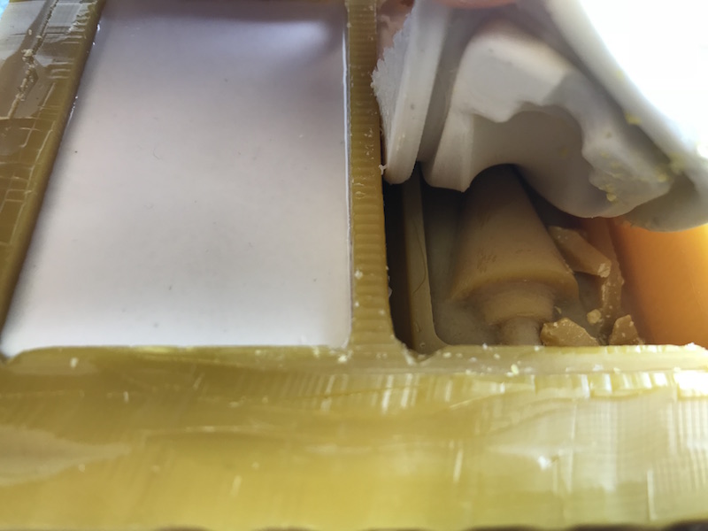
I designed my 3D object too deep in the wax block. The top edge of the cone shell was 10 mm from the top edge of the wax block (z = 0 mm). This had caused the milling time to be too long (about 4 hours) and that I had filled up a lot of the silicone compound. Another aspect was that removing it from the mold would have been much more difficult with a large mold thickness or depth than if I had made the mold flatter. As a result, when removing the second negative mold, I have damaged the milled form as to see on the folowing image. It can still be used in white because only the connecting groove has been damaged.
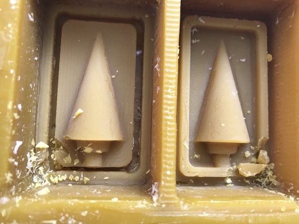
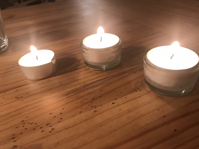
Casting the Endform out of Wax
To make the final shape, I used wax from a candle by lighting the candle and waiting for some of the candle's wax to melt.
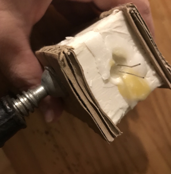
Before, I put the two negative molds together and clamped them with a screw clamp. On both sides I made pieces of wood to prevent the flexible silicone molds from bending when compressed.
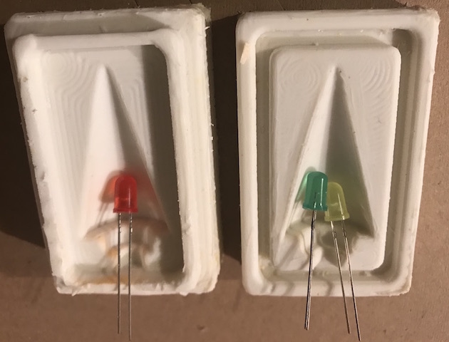
Before plugging both silicone molds, I hung LED in each green, yellow and red in the mold so that the wire protruded out of the mold so it could later be soldered to the board. The LEDs should be switched on later depending on the indoor air quality and depending on the interconnection and programming.
I poured the melted candle wax in a thin stream into the prepared mold and I could see the rising air bubbles.
Since there was also an inaccessible corner for the casting, I kept the shape a bit slanted.
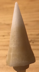
And so looked the finished cast piece after removing it from the silicone mold 4 hours later.
The surface was not quite smooth because at the junctions of the two moldings, the bond was not tight enough so that a thin bead of wax had formed along the surface of the finished piece.
This unevenness was very easy to remove with a scalpel.
And than I made LED-Test using 3V lithium cell.
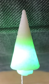
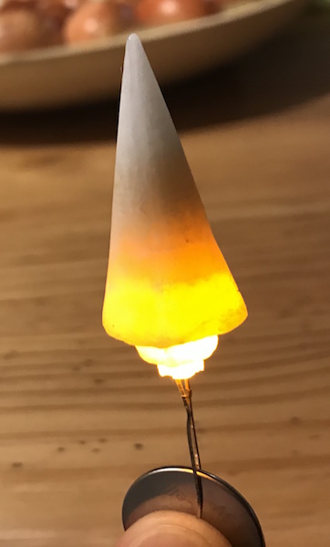
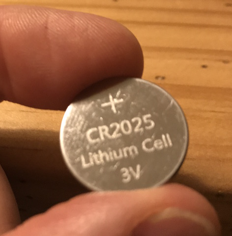
As you can see, the green LED in green looks blue-green in the photo ...
And once again I put together all three steps of the manufacturing process:
Downloads
| SunRay.f3d | download f3d-Design of the Mould; CAM; |
| GCodeSunRay | download gCodeSunRay |