Week 3 – Model a possible final project
This week I’ve been learning some different 3D design software packages and also working through some basic design problems with my current idea for a final project - a food dehydrator.
Initial sketch
I already did some sketches of a possible finished project, including this one, for which I used the Paper app on an iPad.
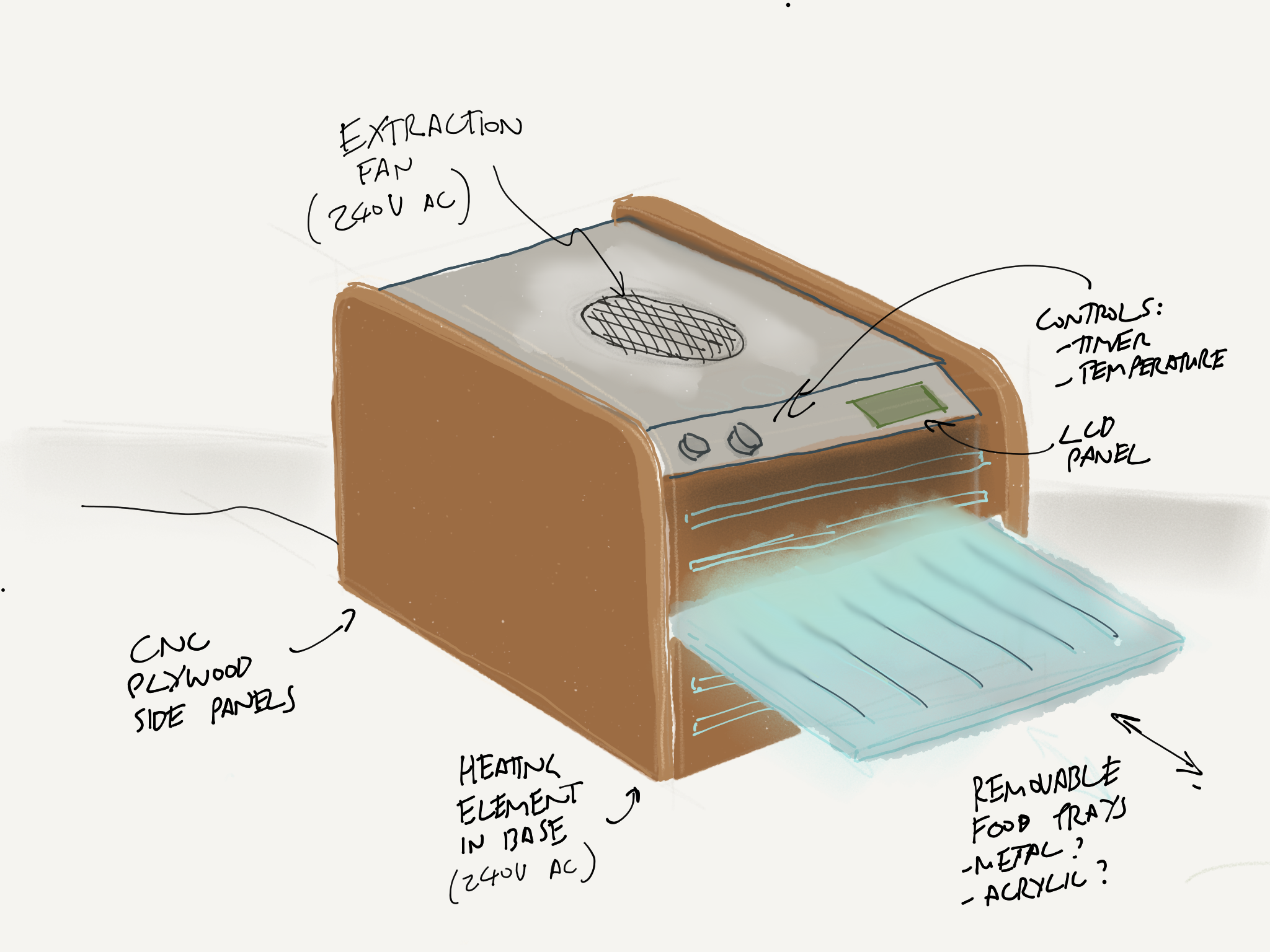
Since then I’ve been researching some of the design principles of food dehydrators and figuring out some specific problems I need to solve.
Focusing on specific problems
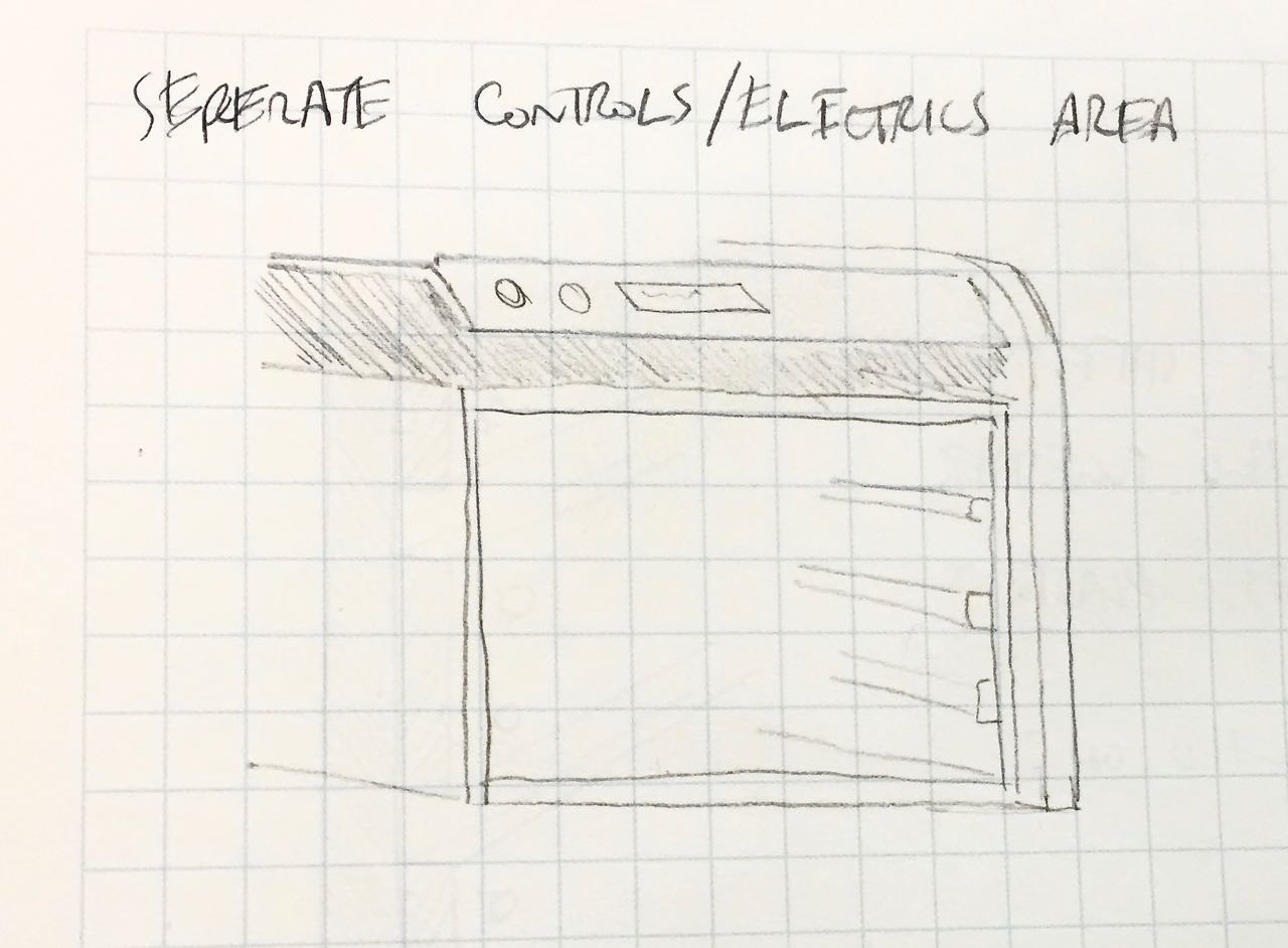
My original idea was inspired by the design of old synthesisers, where a metal box is enclosed between two end ‘cheeks’, often made from decorative wood. In my case, I ‘d envisaged using 18mm birch ply for he end cheeks, and perhaps aluminium or polycarbonate plastic for the box.
This sketch shows how they might fit together:
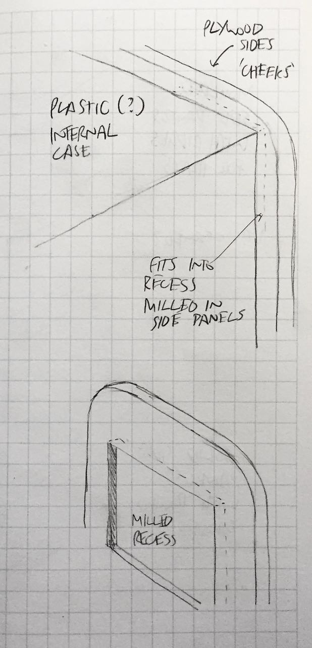
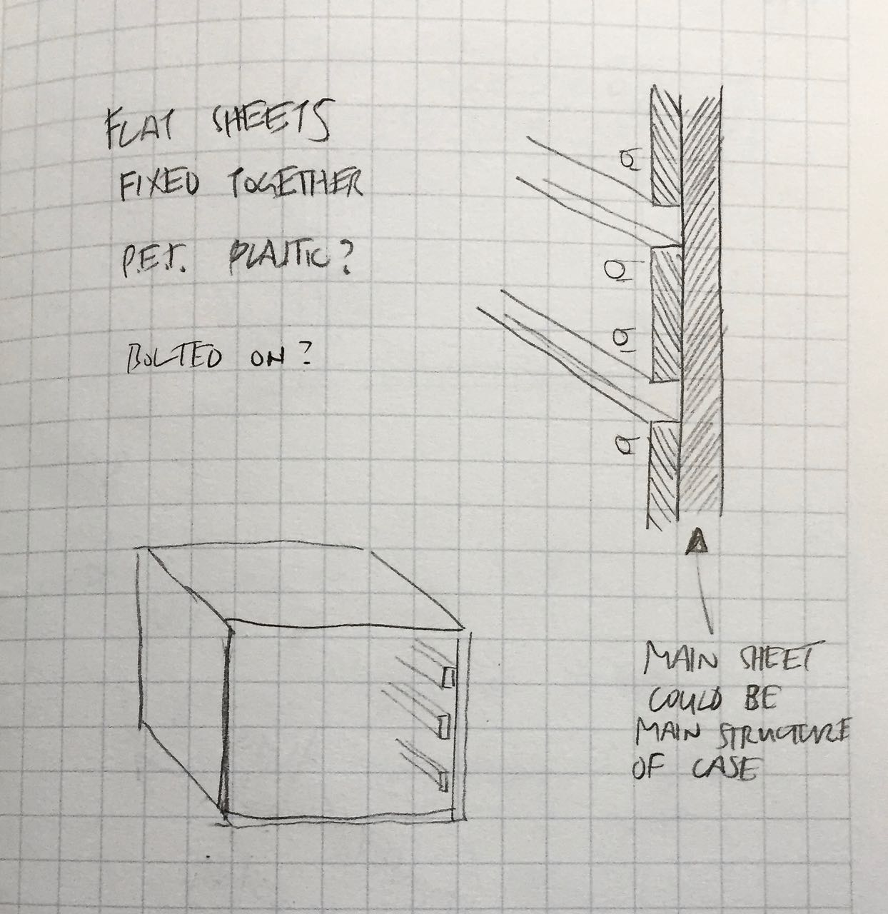
That was a nice idea, but I need to focus on the core functionality first, for example, what to make the main compartment out of. It needs ot be food-safe, easy to clean, and tolerate moderately high temperatures. Polycarbonate meets these criteria, but introduces some questions about how to fit the food trays into the compartment. I sketched a few alternatives.
Moulded vs milled grooves. I’m not sure that polycarbonate (in cost-effective thicknesses) could be milled like this. Maybe it can be moulded, but to what level of quality?
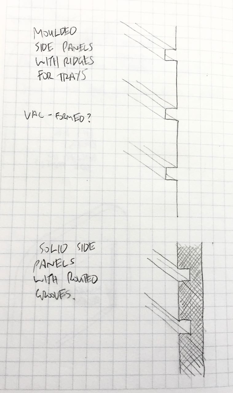
Plywood could easily be milled like this but wouldn’t be a good material for the inside of the dehydrator.
Perhaps a second layer of shims could be attached onto the side walls to act as shelf supports. Although this would make the unit difficult to clean…
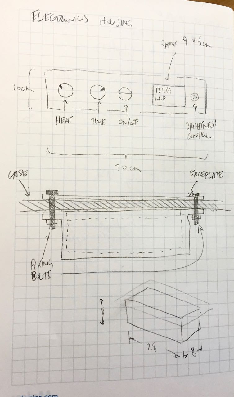
I also need to consider how the electronics components will be housed - and isolated from the heat, and possible liquids in the main compartment:
And I started to think about what controls would be needed, how much space they would take up, and what sort of housing I could design that perhaps could be 3D-printed later on in Fab Academy.
2D CAD
I actually switched to a different idea for my final project, so didn’t pursue these ideas any further.
However I used 2D CAD extensively in my final project. I had to design a chassis to hold all my circuit boards, as well as a case to enclose the whole project. These were all 2D parts (the case was folded from a flat sheet milled on the milling machine; the chassis was made from a series of flat acrylic sheets cut on the laser cutter).
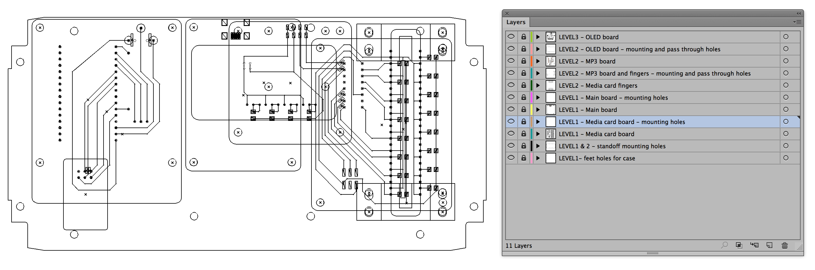
As I already use Illustrator as in my workflow for producing boards (exporting a DXF from Eagle, then adjusting layers, and optimising traces for the milling machine) I have templates for all the boards including component placement, mounting holes and board outlines.
So I used created Illustrator files with all my board templates so I could adjust these as I iterated through prototypes in the final production of that project. For more, see:
3D modelling
Trying different packages
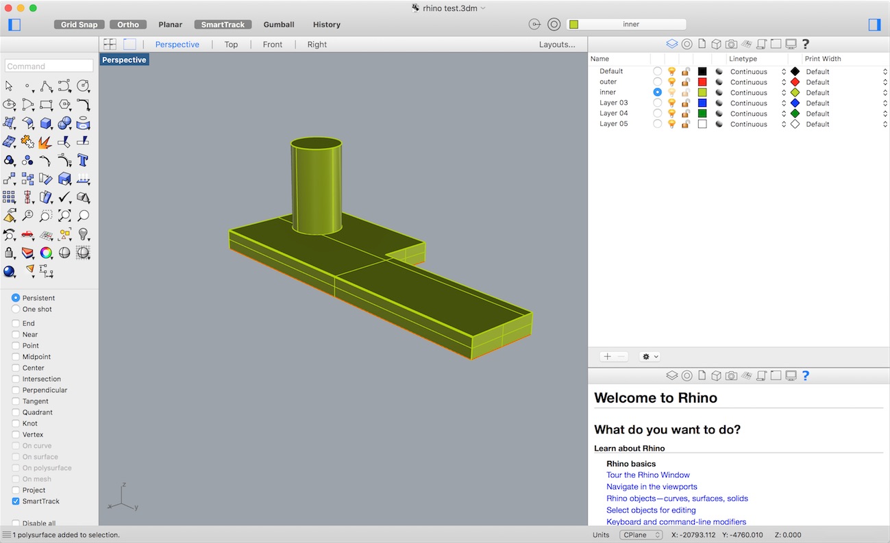
I’ve used 2D software, including Photoshop and Illustrator, for many years. I’ve also used Inkscape when preparing files for the laser cutter. And I’ve used Sketchup for many DIY projects, including our campervan build. But I haven’t used any professional 3D tools before. This week we had some quick lessons in Rhino and Fusion 360.
A test object in Rhino
A test object in Fusion 360
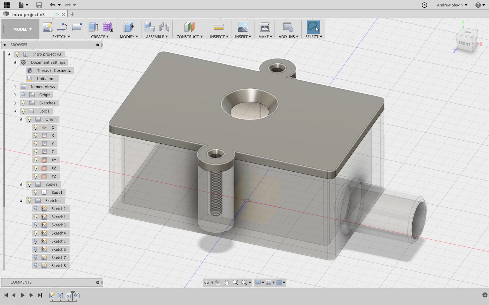
I really enjoyed playing with Fusion 360, so I’m currently using that to model some parts of the project:
- a simple housing for the electronics
- an overall case design, so far focusing on a method to support food trays
An idea for the overall external case shape
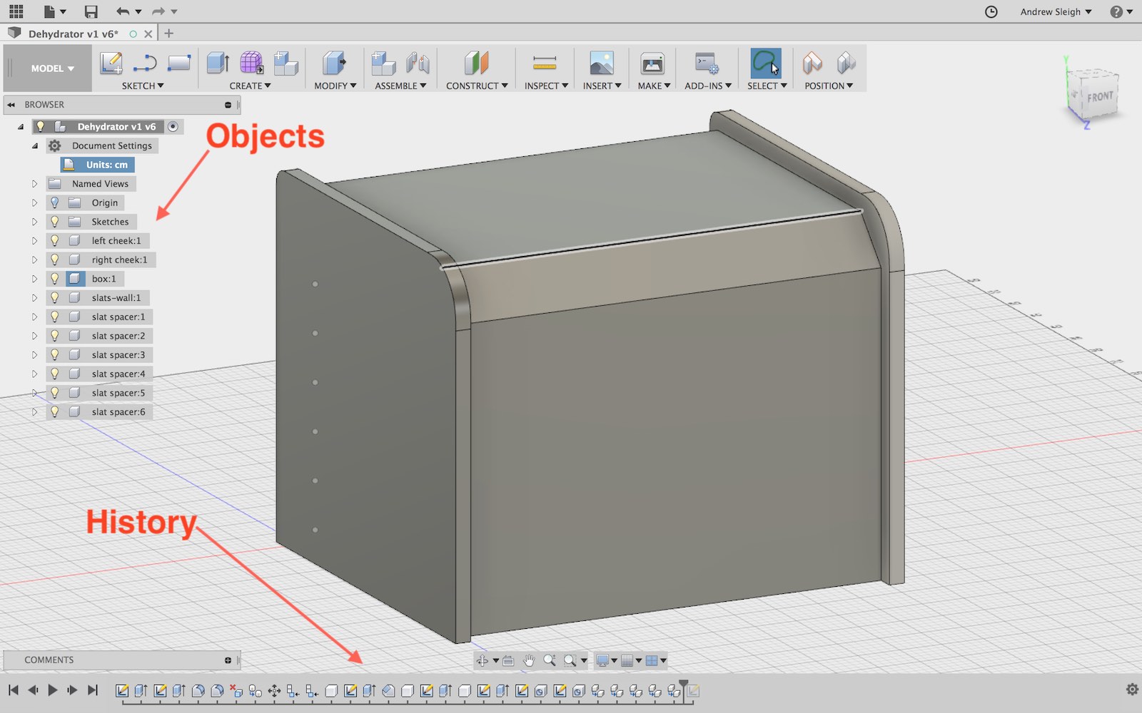
Already there are some aspects of Fusion 360 that feel very powerful. I love the logical breakdown of the model into individual parts: bodies, components, sketches, origins, etc. For example, in the design I’m working on, I have multiple slats, all of the same size, with standard bolt holes. So I can make one, copy it, make changes to the original and those changes propagate out to all the copies:
Similarly, the timeline lets you go back to an earlier stage in the build of the model, change a parameter, and then have the change ripple through all subsequent steps on the model build, including extrusions, fillets and making holes or cuts.
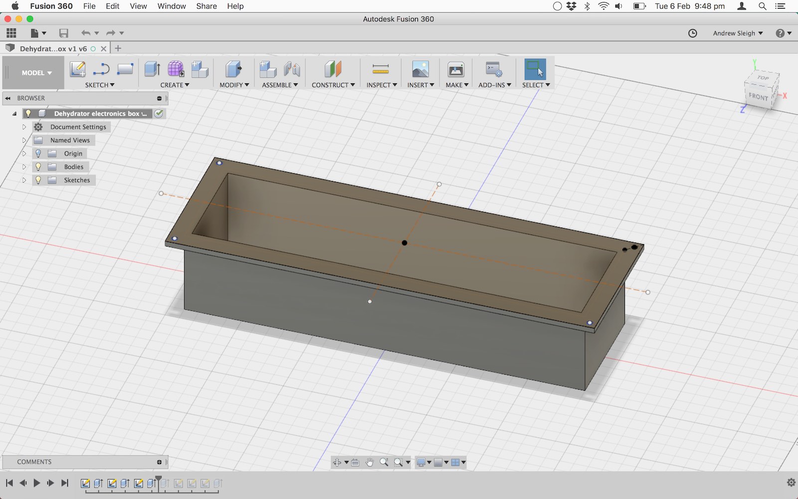
As well as the main enclosure, I’m trying to make a simple 3D-printable casing for the electronics, to keep them separate from the main compartment, which is heated, and contains messy food and humid air. Pretty basic so far…
Files
Eagle files for my board