Week 7 - Redraw the echo hello world board, with extra components
Now we’re learning the tools that generate the designs to mill our own boards. In effect, the step before last week.
This page is long, I tried several boards before I got one that worked. Skip to:
Redraw the board
I’m using Eagle. It’s got a pretty awful UI, like a Windows app ;-). Can you guess what you click on to add things to your empty schematic?
Anyway, I figured out the mystery meat navigation slowly.
I downloaded some libraries of components, mostly from Sparkfun, I also downloaded some specific libraries for the ATTiny processors.
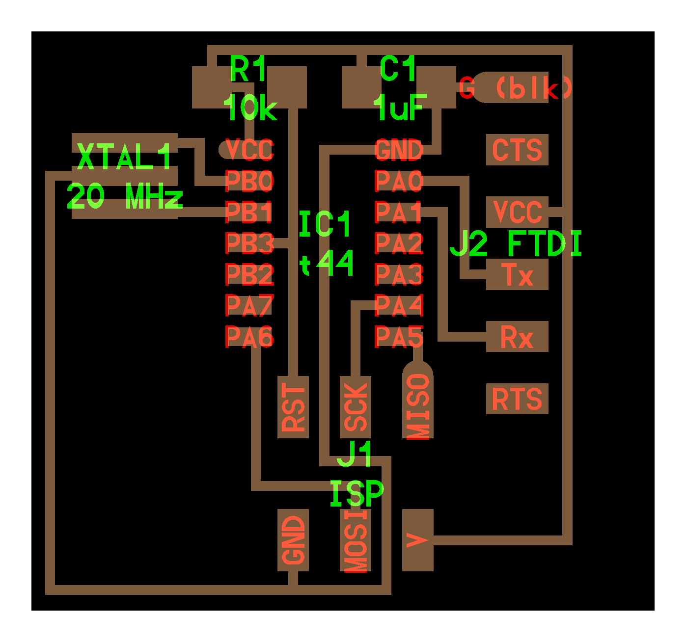
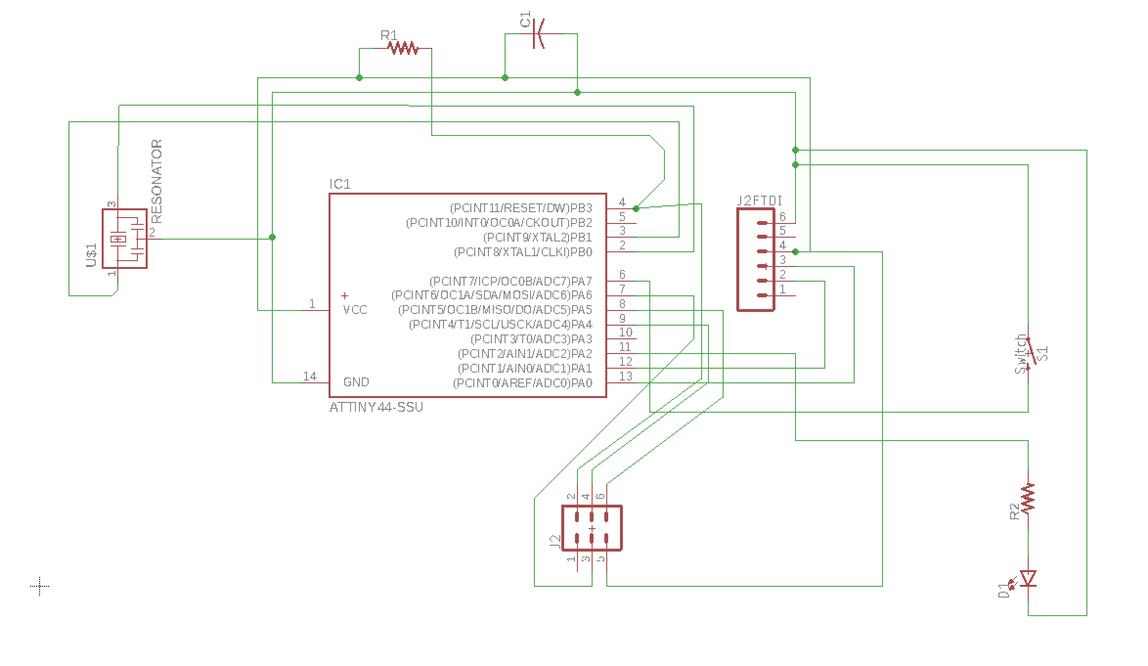
Then I populated my schematic with parts, based on the reference diagram:
Parts come in different package sizes. I found this chart to help try to figure out which size we’re using:
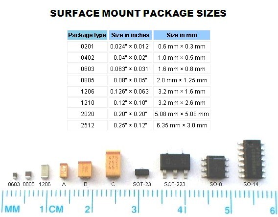
(I’m going with 1206 for now)
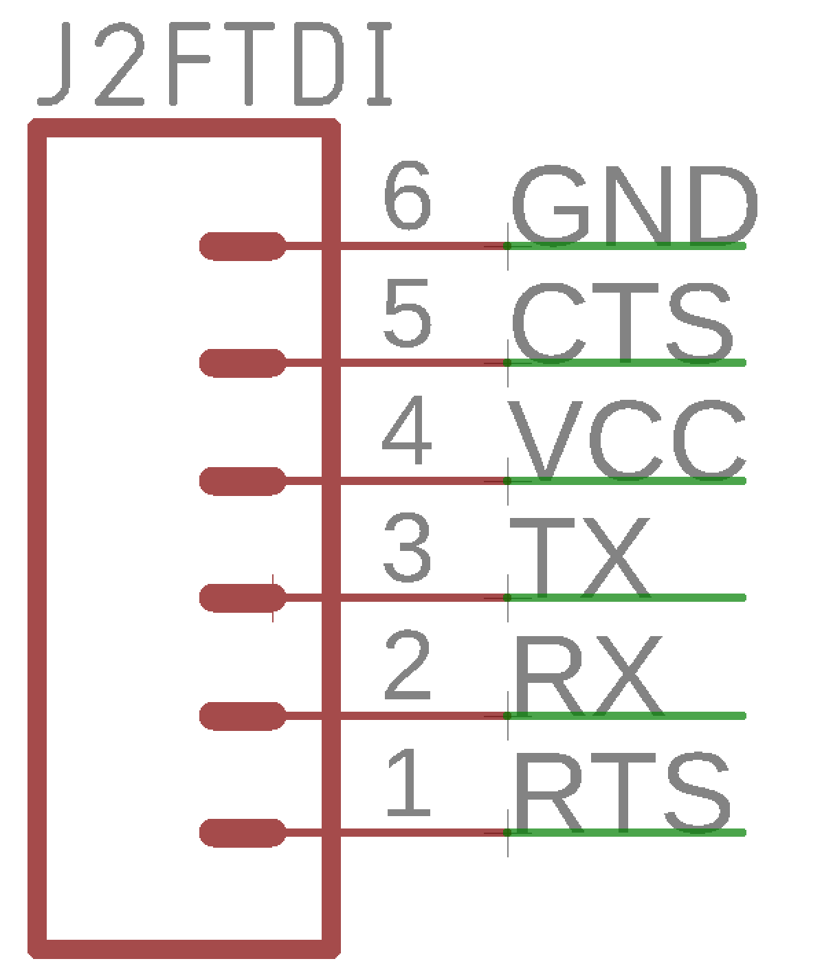
I notice that the pins on my J2 FTDI are labelled slightly differently (RTS vs DTR). Hopefully this won’t make a difference.
And I see that the ISP headers (in the Sparkfun libraries) also come in a variety of packages, and I’m not sure which one is appropriate. I just picked the first in the list.
On the board diagram the crystal has 3 connections, but in the Sparkfun library, they all have 2. Maybe this is intended to be a resonator(?) so that’s what I’m using for now. Again, not sure of the package size, so I’m starting with a RESONATOR-SMD-4.5X2.0 (Version 1) package. SO here’s my first attempt:
I switched to board view, arranged the components to be roughly placed as on the reference board, then found a button labelled Autorouter. Sounds promising! So I pressed it, and ended up with a board like this:
Different colours represent different layers of the board, so it looks like some of my traces are being routed on the bottom (blue lines) and some on the top (red lines). So I need to fix this. Also, it’s a mess.
I hit ripup and then Go to start again. I tidied up the components a little, then used the draw tool on the (20) Dimension layer to set up the outline of the board.
This time, I’ll use the route tool. I switched it to Single Layer Mode.
I didn’t really look at the other design rules, like trace width or drill size. I just tried to route all the races without overlaps. Here’s my first attempt:
Now I need to go back and check the design rules for our mill and boards, and also which components and packages we actually have in the lab.
Starting again
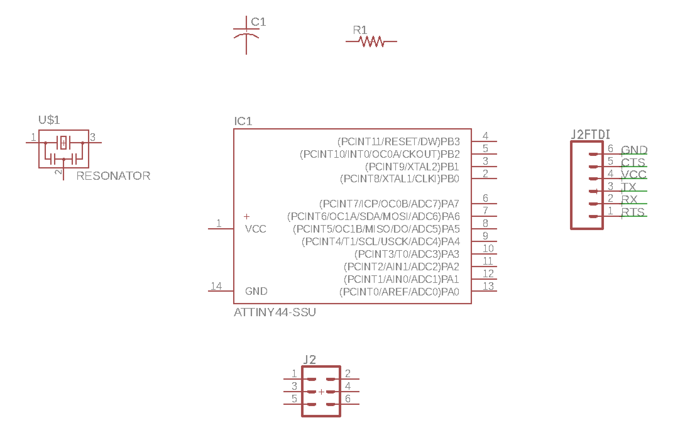
We made a reference sheet for all the parts needed to tie together what we have in the lab, and where to find them in Eagle: Echo Hello World Board components
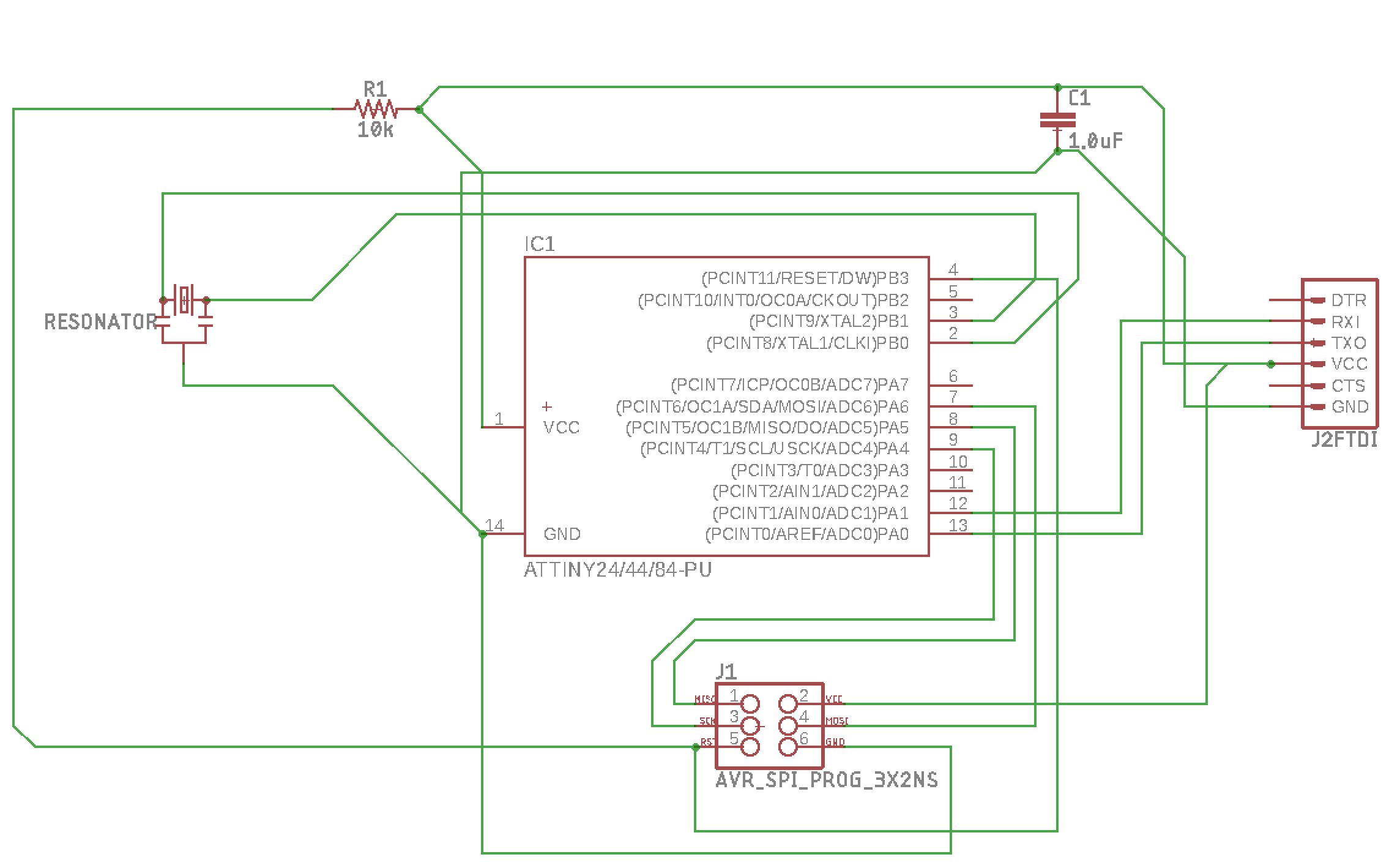
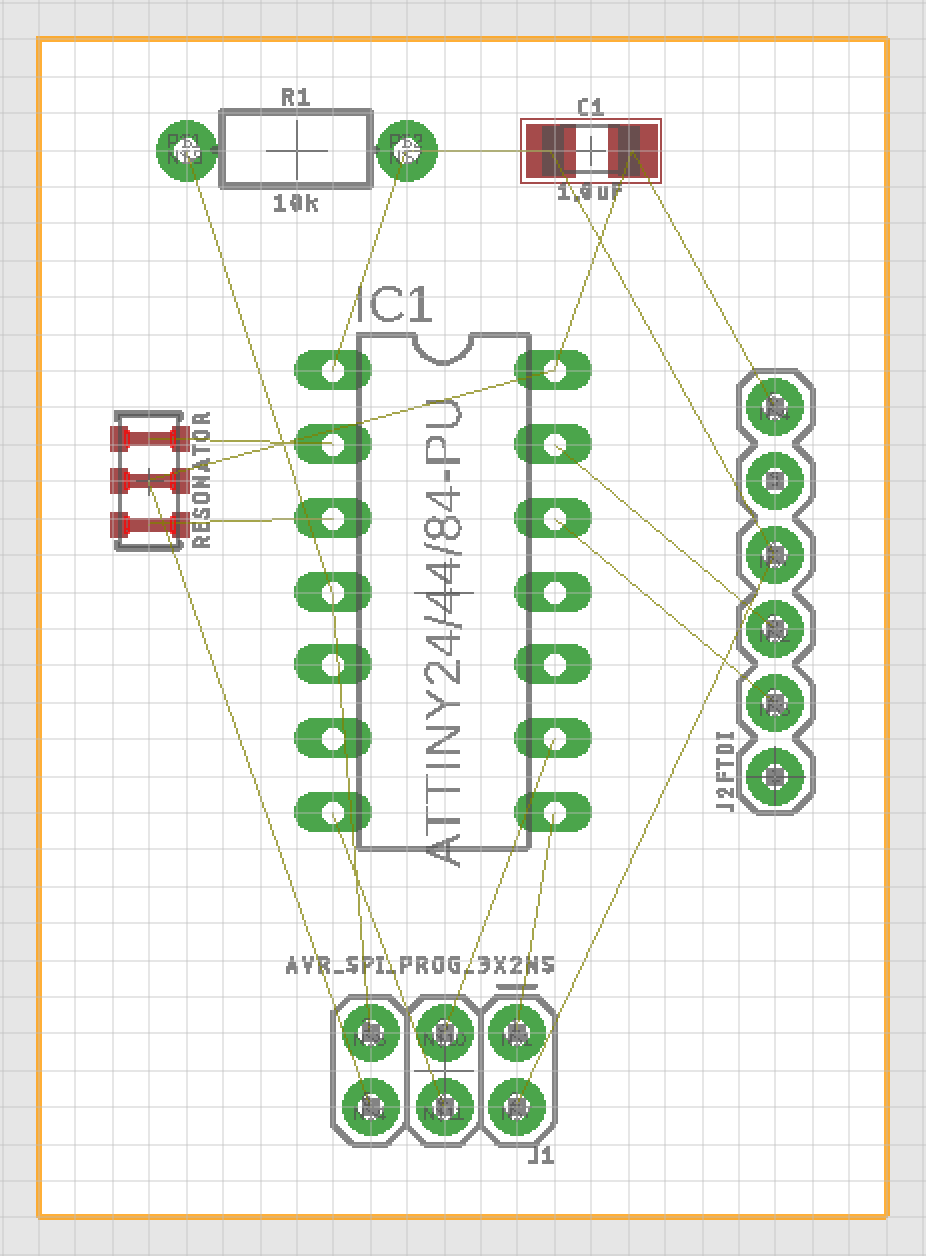
I started a new schematic with (I hope) the correct parts:
For the generic parts without labels, I added some:
All the parts on the schematic and connected up:
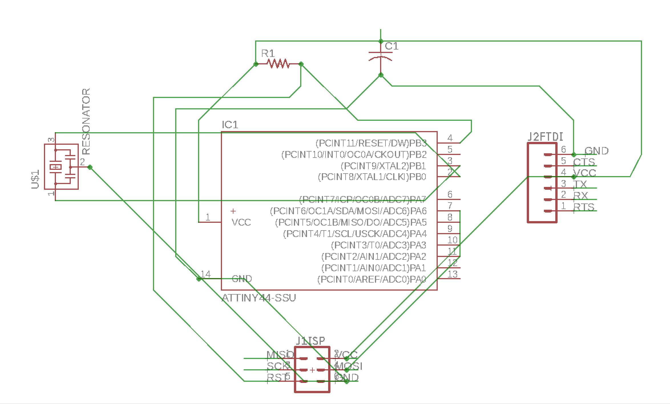
Then I added the new components, a switch and LED. There are two free pins on the ATTiny, PB2 and PA7, so I’ll connect each of these to one of these pins, and then to GND.
Design Rules
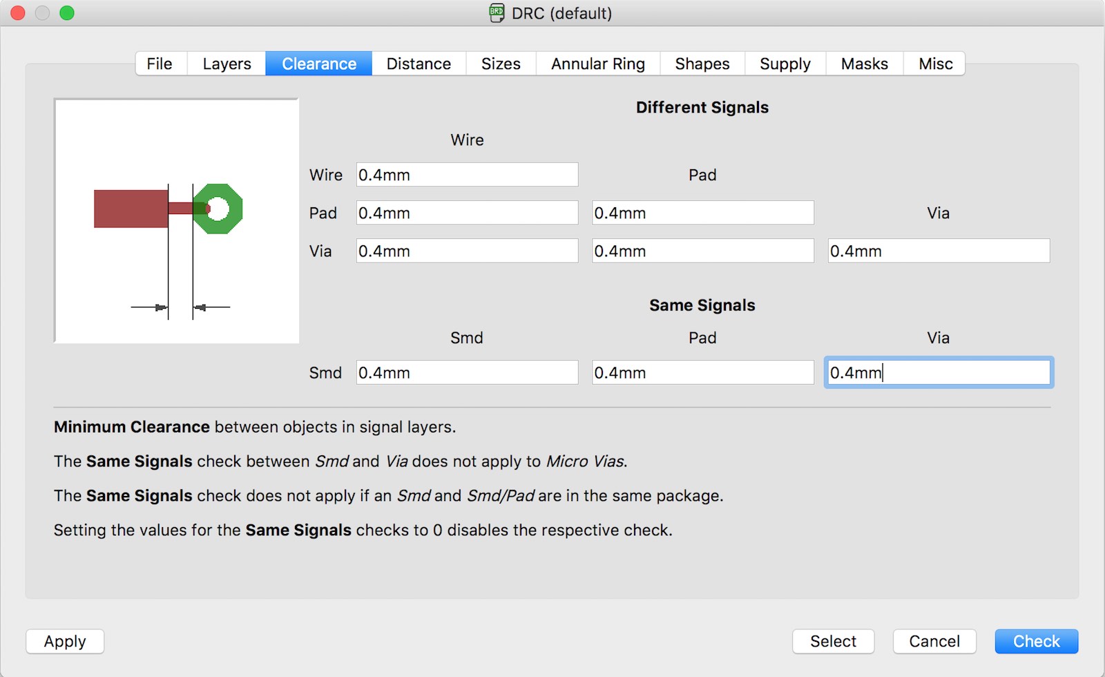
I need to check this – perhaps by following the process through to generating a PNG file for milling. For now, I’m using these rules for clearances - making them all 16mil (in metric, that’s 0.4mm):
I’m struggling to find a way to route my traces:
I seem to have made lots of unnecessary connections, so starting again with a better understanding of how everything connects, and trying to avoid duplicate connections to GND and VCC especially.
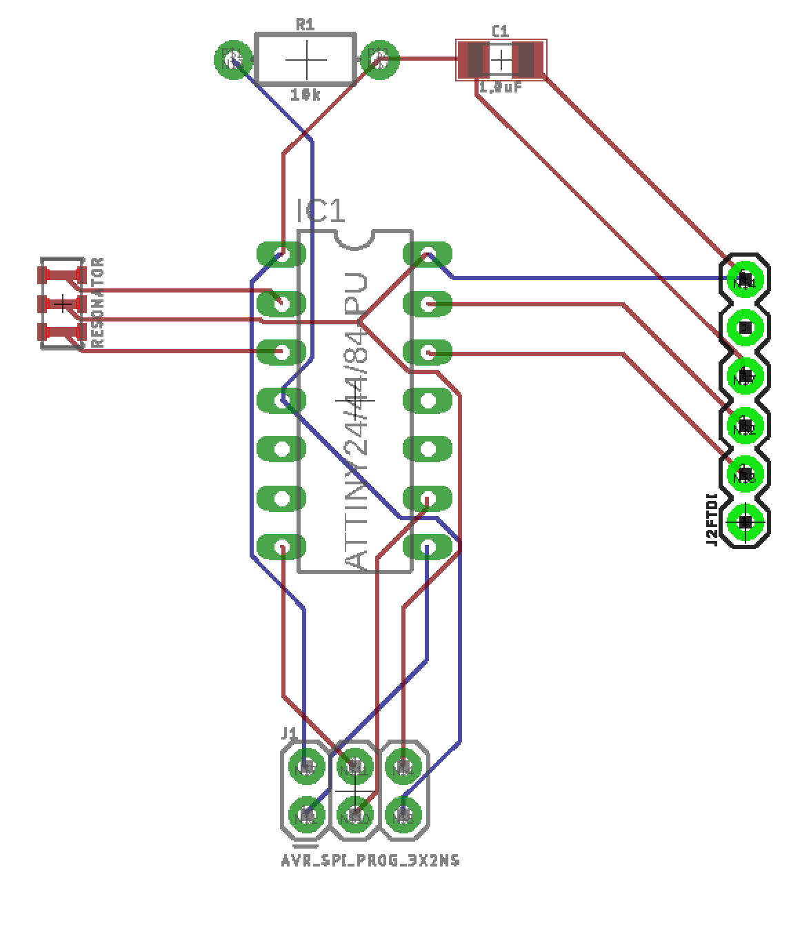
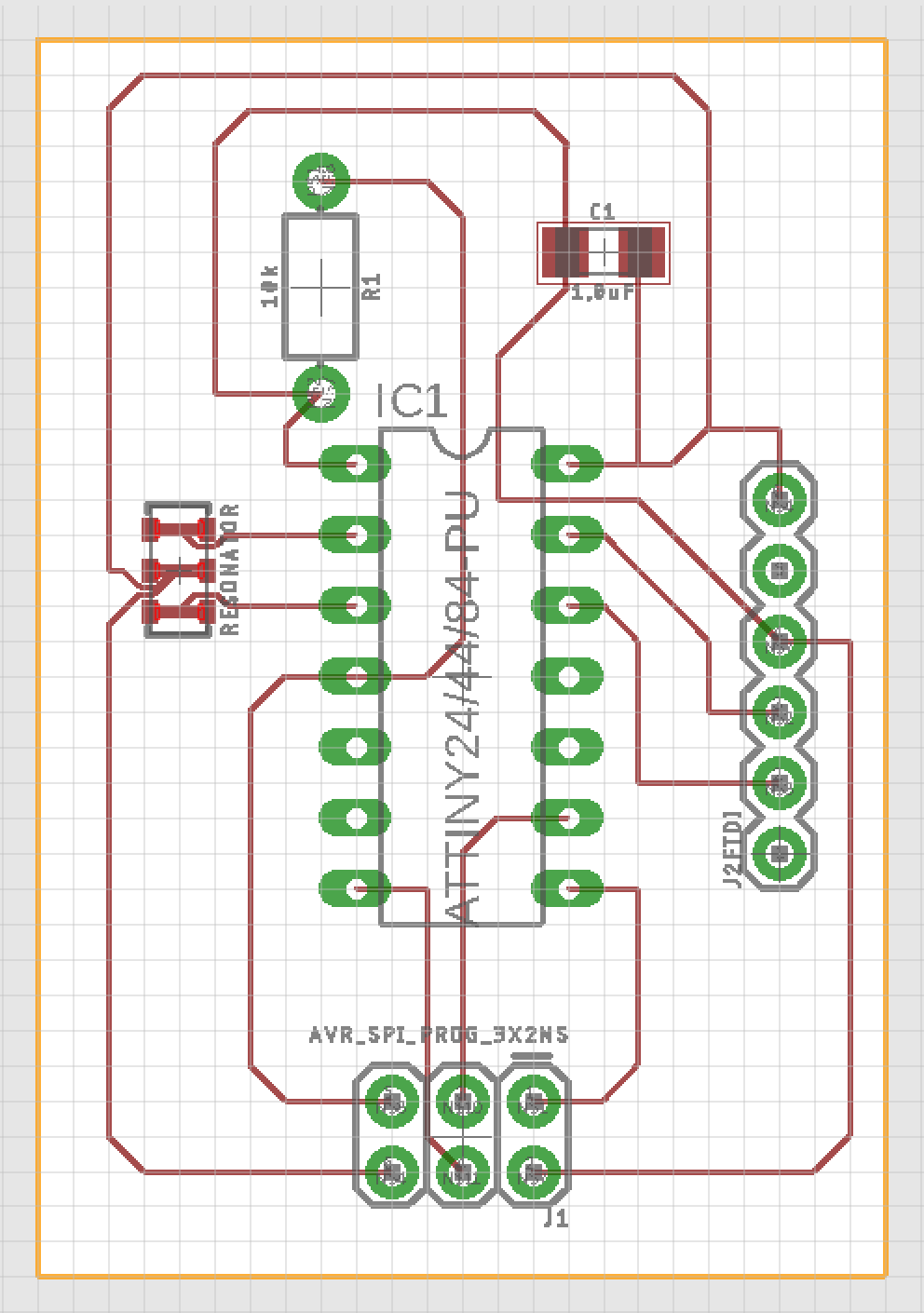
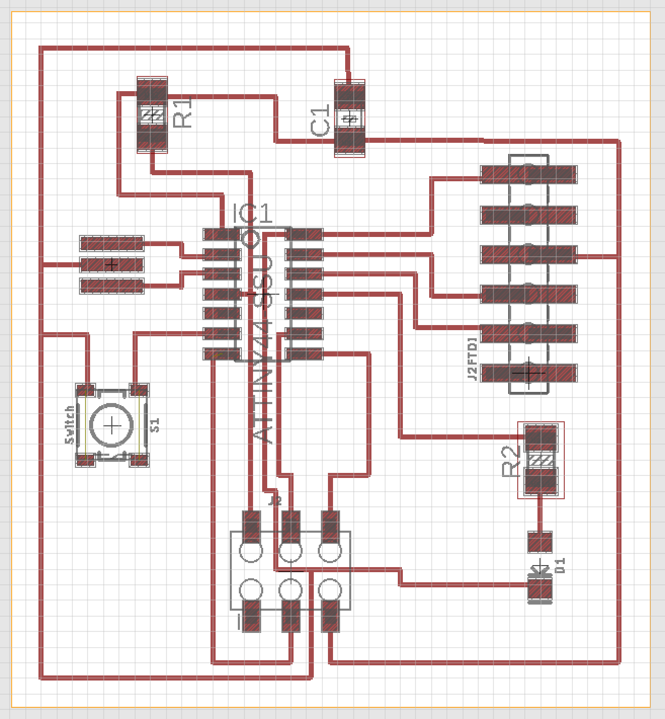
Starting again, again:
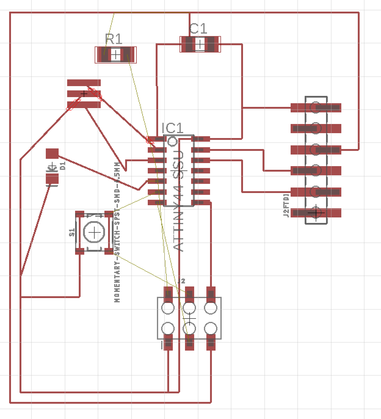
Routing all the traces on the board view, I end up with this:
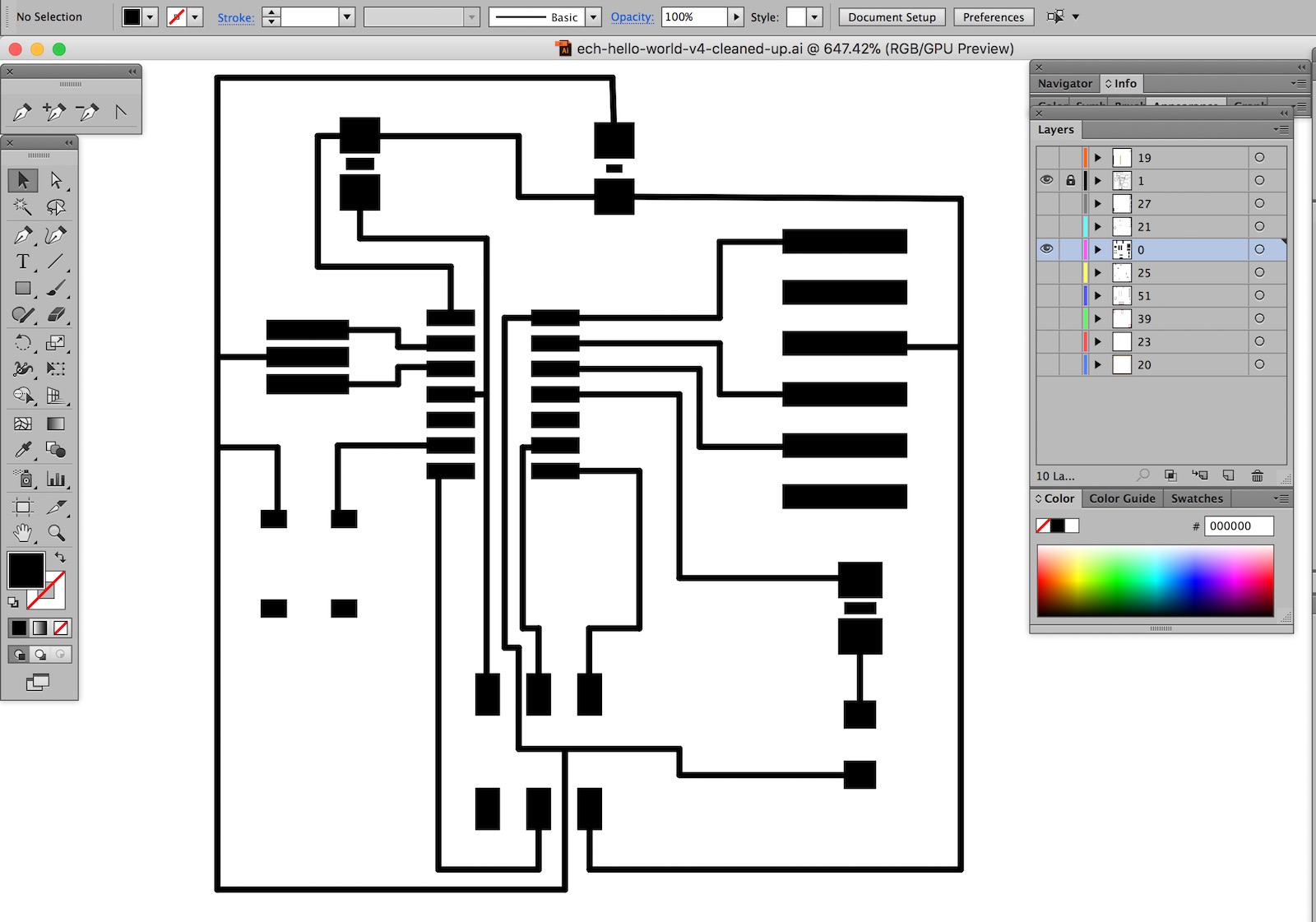
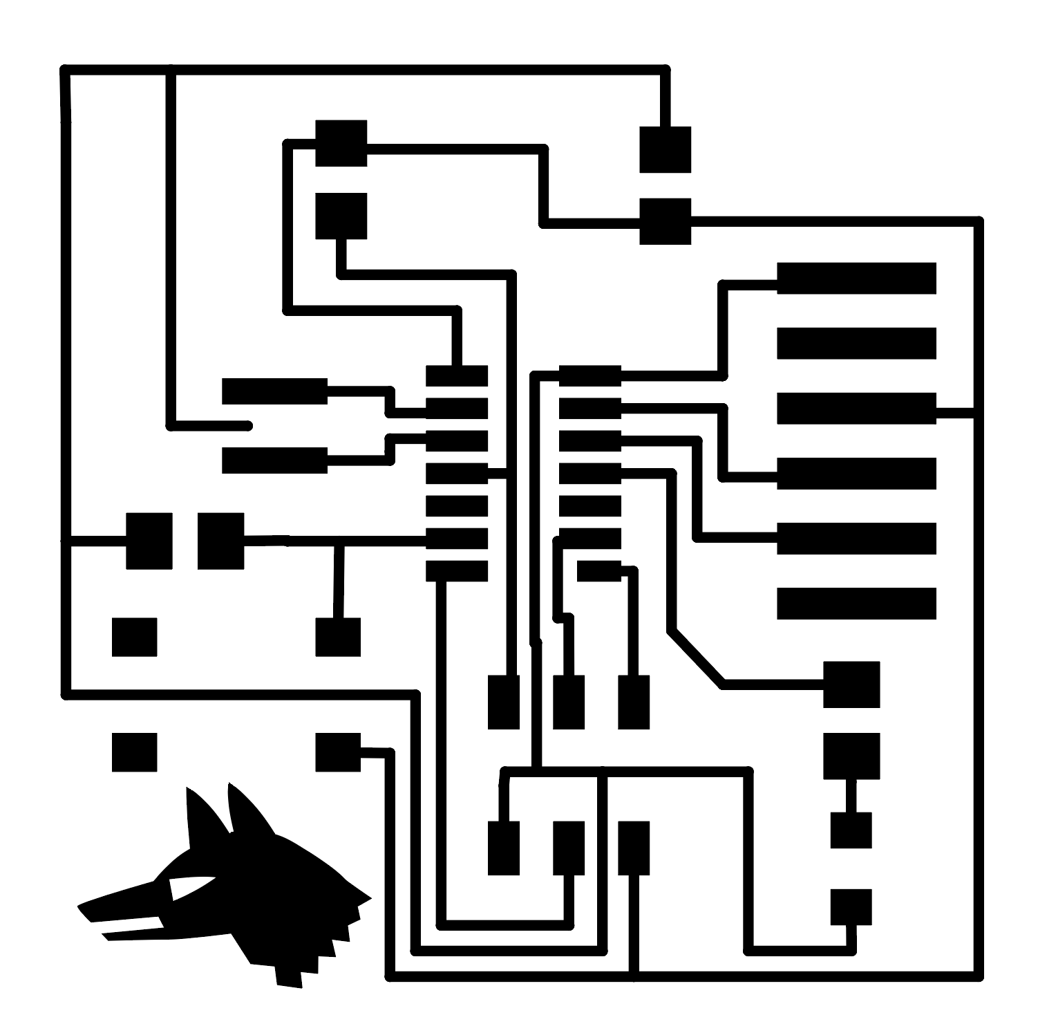
I exported this board as a DXF, then opened it in Illustrator, at original size. Then I printed out onto paper – again without changing the size – and placed some of the components on the paper to check for fit.
I cleaned up some of the traces in Illustrator, hid all the layers except the pads and traces, and resized the artboard to be the same size as the artwork (including board outline).
I exported the pad and trace layers together as one 1000dpi png.
Preparing to mill
I inverted the png in photoshop to make the traces white, on a black background
I also adjusted a few of the traces here, removing some unnecessary pads, and altering the resonator traces to allow more freedom of movement for the resonator.
Milling
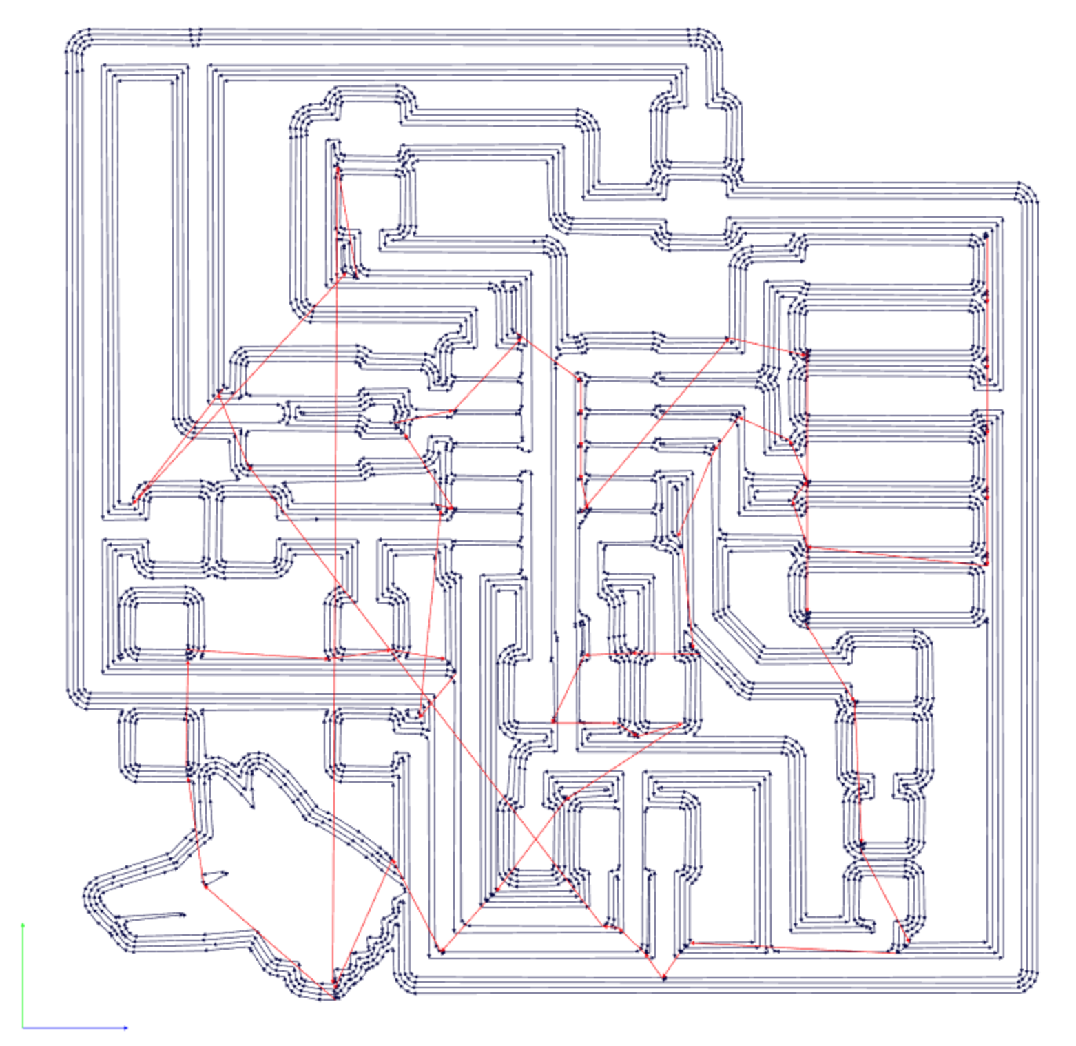
I opened the trace png in fabmodules.org and calculated tool paths with these settings (ref google doc):
Machine: Roland MDX-40
Process: PCB Traces
Tool: 2 (0.4mm)
Speed 4mm/s
x=0, y=0, z=0
xhome=0, yhome=0 zhome=0??
zjog=2
Cut depth=0.1mm
Tool diameter=0.4mm (1/64”)
Num of offsets=2
Offset overlap=50%
Path error=1.1pixels
Image threshold=0.5
Whilst milling, we noticed a problem with the z home. Using the Z0 sense tool to calculate Z0, resulted in cuts that were just a little to shallow. So after a few traces had been made, I canceled the job, set Z0 0.1mm lower than before, and sent the job again.
This problem could be due to dirt on the tool causing the machine to mis-calibrate either when changing the cutting tool, or when using the Z0 sense tool.
Then I cut the outline. As my outline was very thin, I used a workaround, telling the machine that it was a 0.3mm diameter tool, although it’s actually 1mm, so it calculated more repetitions of the path in order to actually cut through.
Tool 1 (1mm)
Tool diameter: 1mm
Cut depth: 1.7mm (assuming material thickness of 1.6mm)
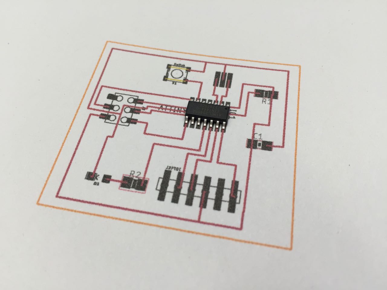
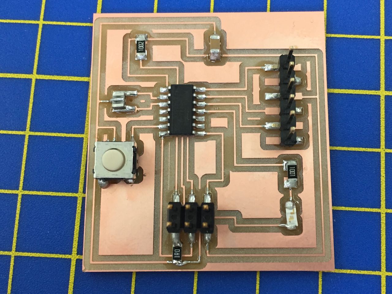
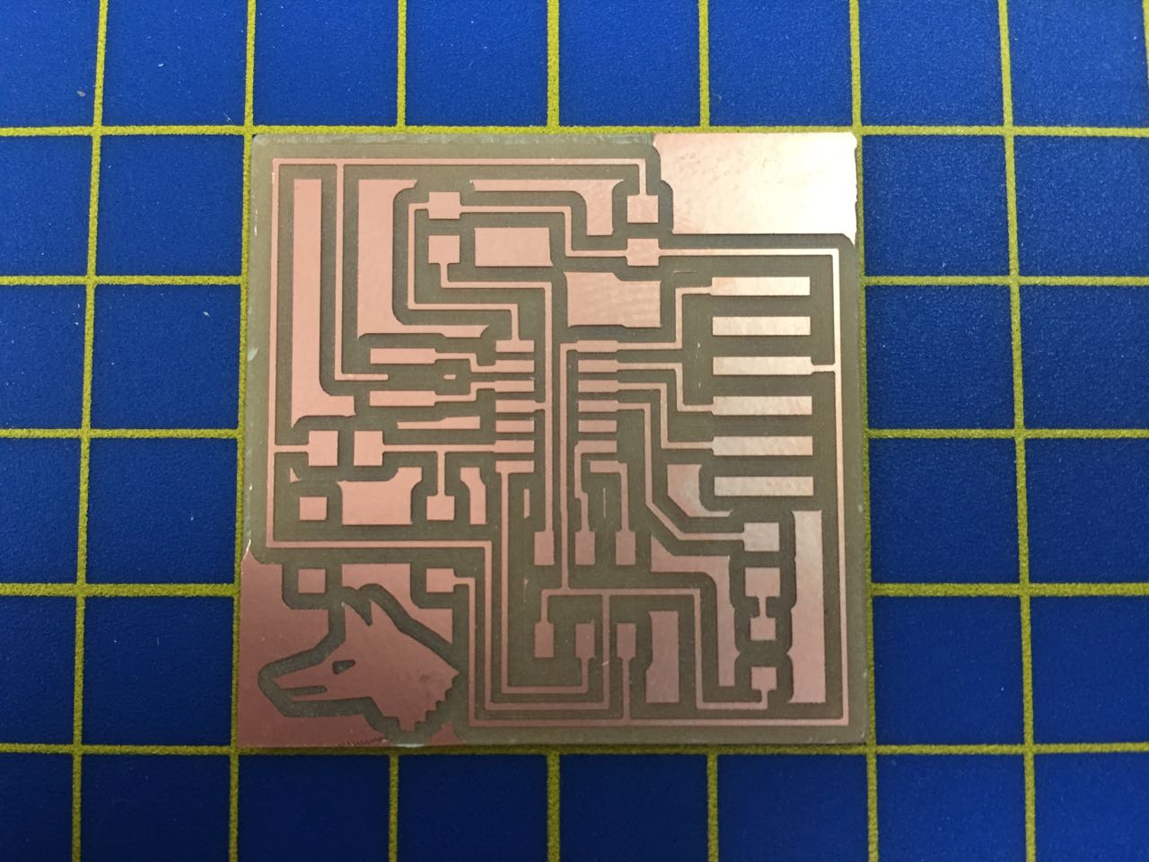
The result:
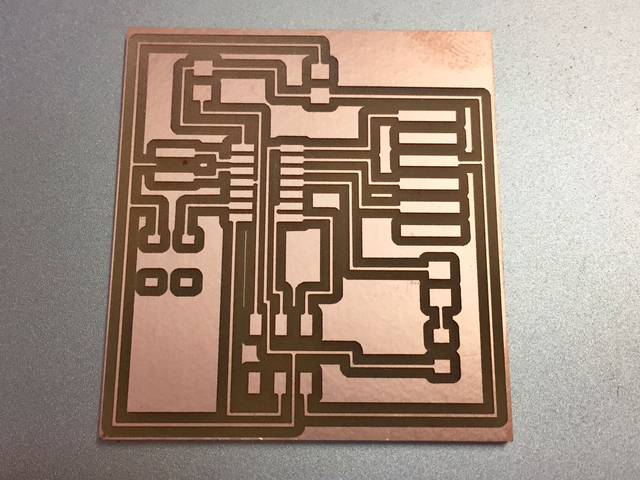
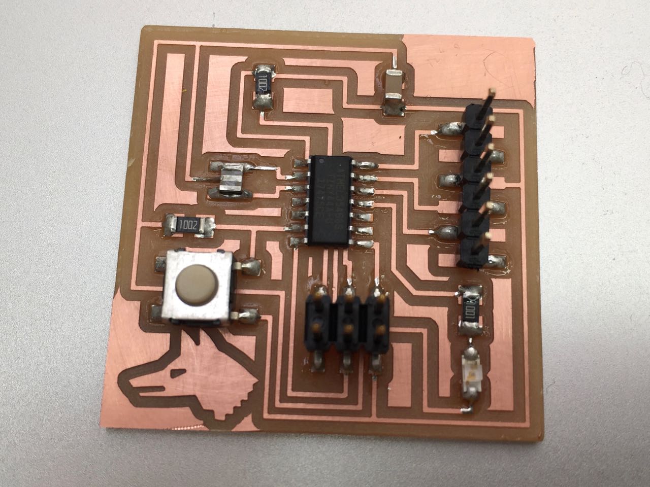
I then soldered my components. In the course of soldering, a few problems became apparent:
I was able to work around these issues – with the switch, by bending the legs of the switch underneath the body to make it fit – though this was to cause problems further down the road.
Programming the board
I used the instructions here:
Installing ATtiny support in Arduino 1.6.4
In Arduino 1.6.4, you can install the ATtiny support using the built-in boards manager.
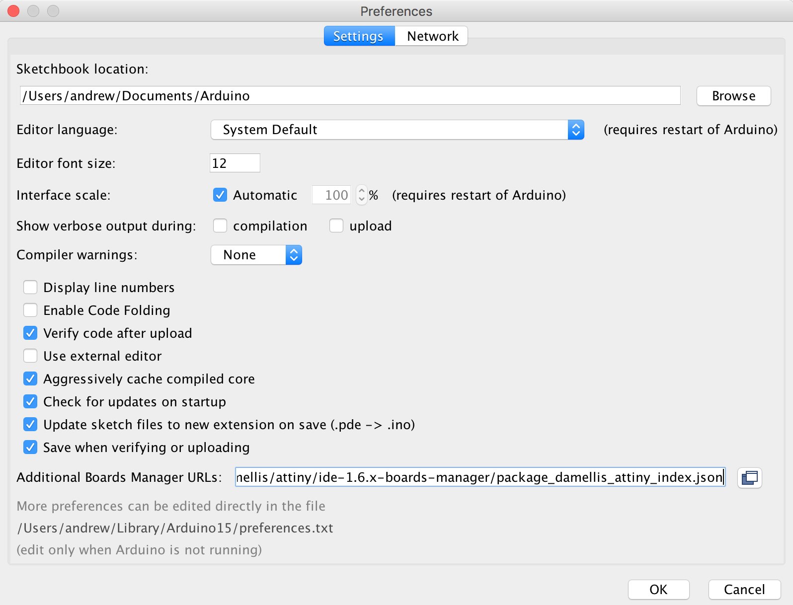
* Open the preferences dialog in the Arduino software.
* Find the “Additional Boards Manager URLs” field near the bottom of the dialog.
* Paste the following URL into the field (use a comma to separate it from any URLs you’ve already added):
https://raw.githubusercontent.com/damellis/attiny/ide-1.6.x-boards-manager/package_damellis_attiny_index.json
* Click the OK button to save your updated preferences.
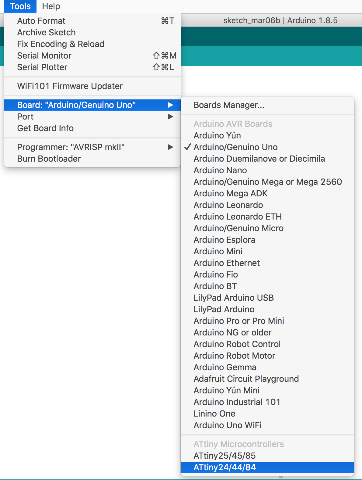
Open the boards manager in the “Tools > Board” menu.
Scroll to the bottom of the list; you should see an entry for “ATtiny”.
Click on the ATtiny entry. An install button should appear. Click the install button.

Close the boards manager. You should now see an entry for ATtiny in the "Tools > Board" menu.
I looked at the Github repository
I’m using Arduino version 1.8.5. In the Readme file, there are instructions for which branch to use:
If you are using Arduino 1.6.x IDE the just use the master branch.
If you are using Arduino 1.0.x IDE, then use the ide-1.0.x branch.
Back to the main instructions:
* If you haven’t already, download the Arduino software, version 1.0.6. Install the Arduino software, following the instructions for Windows or for Mac OS X.
* Download the ATtiny files for Arduino 1.0.x: ide-1.0.x.zip
* Unzip the attiny zip file. It should contain an “attiny-ide.1.0.x” folder that contains an “attiny” folder.
* Locate your Arduino sketchbook folder (you can find its location in the preferences dialog in the Arduino software)
* Create a new sub-folder called “hardware” in the sketchbook folder, if it doesn’t exist already.
* Copy the “attiny” folder (not the containing attiny-1.0.x folder) from the unzipped ATtiny.zip to the “hardware” folder. You should end up with folder structure like Documents > Arduino > hardware > attiny that contains the file boards.txt and another folder called variants.
* Restart the Arduino development environment.
* You should see ATtiny entries in the Tools > Board menu.
All good so far:
Now following our own instructions for programming the board.
Select ATTiny22/44/84 from Tools/Boards menu

Then select ATTiny44 from Tools/Processor menu

Then selct 20MHz clock (external) from Tools/Clock menu

Then select USBTinyISP from Tools/Programmer

Then select Tool/Burn Bootloader
This didn’t work for me, with various error messages along these lines:
Arduino: 1.8.5 (Mac OS X), Board: "ATtiny24/44/84, ATtiny44, External 20 MHz"

avrdude: error: usbtiny_transmit: Input/output error
avrdude: initialization failed, rc=-1
         Double check connections and try again, or use -F to override
         this check.


avrdude: error: usbtiny_transmit: Input/output error
Error while burning bootloader.

This report would have more information with
"Show verbose output during compilation"
option enabled in File -> Preferences.
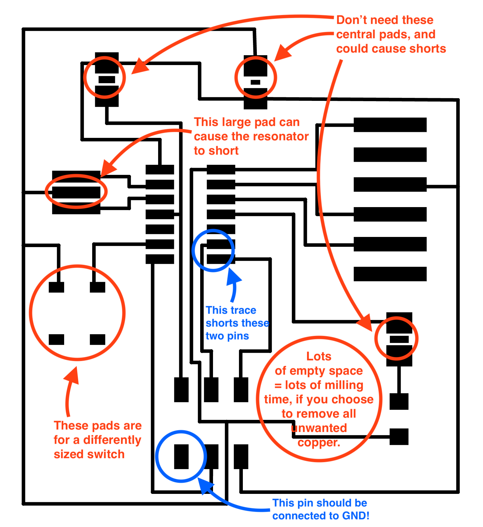
In the course of troubleshooting, I discovered several new problems:
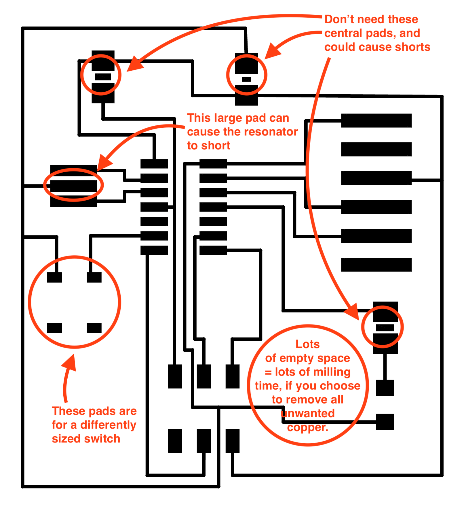
The GND pin on my ISP header was not connected to anything! Using a 0Ohm resistor to bridge a trace, I connected my unconnected pin to GND. There was a problem with my original design, causing a short between 2 pins on the ATTiny
These issues were actually visible on the original PNG artwork:
After fixing these, I was able to burn the bootloader to the board with Luiz’ programmer. I could then upload the blink and button sketches via the programmer to the board (Use Command-Shift-U to upload via the programmer.)
I edited the sketches to use the correct pins for my board. My LED is on pin 2; my switch is on pin 7.
Button sketch (adapted from Arduino example sketch)
// constants won't change. They're used here to set pin numbers:
const int buttonPin = 7;     // the number of the pushbutton pin
const int ledPin =  2;      // the number of the LED pin

// variables will change:
int buttonState = 0;         // variable for reading the pushbutton status

void setup() {
  // initialize the LED pin as an output:
  pinMode(ledPin, OUTPUT);
  // initialize the pushbutton pin as an input:
  pinMode(buttonPin, INPUT);
}

void loop() {
  // read the state of the pushbutton value:
  buttonState = digitalRead(buttonPin);

  // check if the pushbutton is pressed. If it is, the buttonState is HIGH:
  if (buttonState == HIGH) {
    // turn LED on:
    digitalWrite(ledPin, HIGH);
  } else {
    // turn LED off:
    digitalWrite(ledPin, LOW);
  }
}
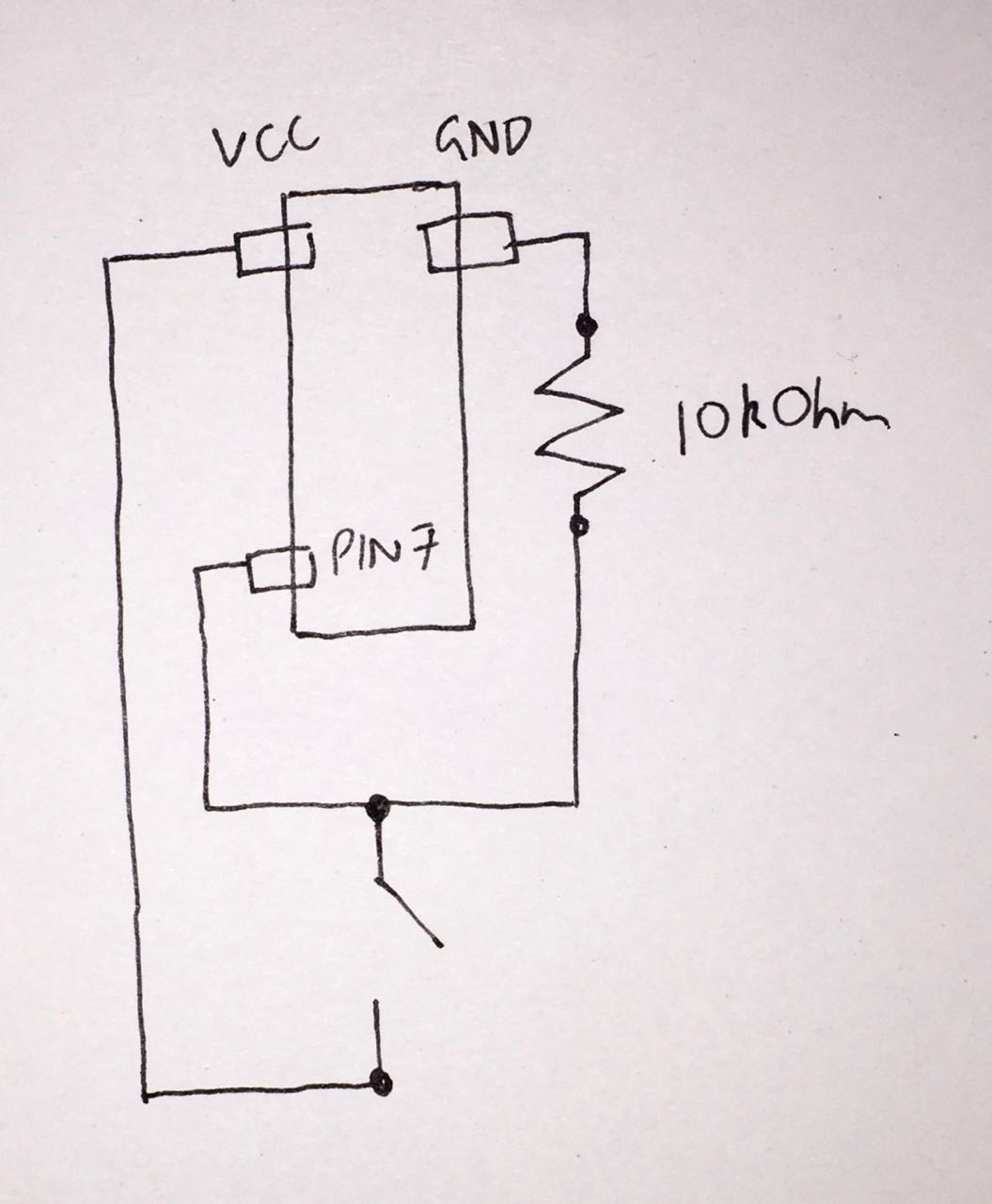
On testing, a new flaw was revealed, this time with the logic of the switch itself.
The pin on the ATTiny wired to the button is set to be a digital input. So it expects a small current at all times, at either a high or low voltage. In the current layout, when open, no current flows, so it cannot sense anything. And when closed, it completes a circuit to GND. This is not a good way to sense high or low voltage - and isn’t even what the sketch expects (it expects high voltage on the pin in order to light the LED, not low voltage).
So I need to redesign the circuit with 2 changes:
- The button is wired to the pin, but also (on the same side) wired to GND, via a high resistance resistor, e.g. 10kO.
- The other side of the botton is wired to VCC (i.e. ‘high’ voltage.)
The resistor stops the pin from shorting when the switch is closed (as VCC is then connected to GND). And it also allows a small current to flow from the input pin to GND when the switch is open, so a digital ‘low’ can be sensed.
Next steps
- Modify button circuit to include resistor, and route the switch to VCC instead of GND
- Swap out button component for right sized button
- Reroute my traces in Eagle to fix trace problems
- Clean my png file again to make more room where the board is shorting
- Create a thicker outline so my board cuts out properly
I’d also like to re-mill my programmer, which didn’t work in this case (I used Luiz’ programmer)
Revised board design
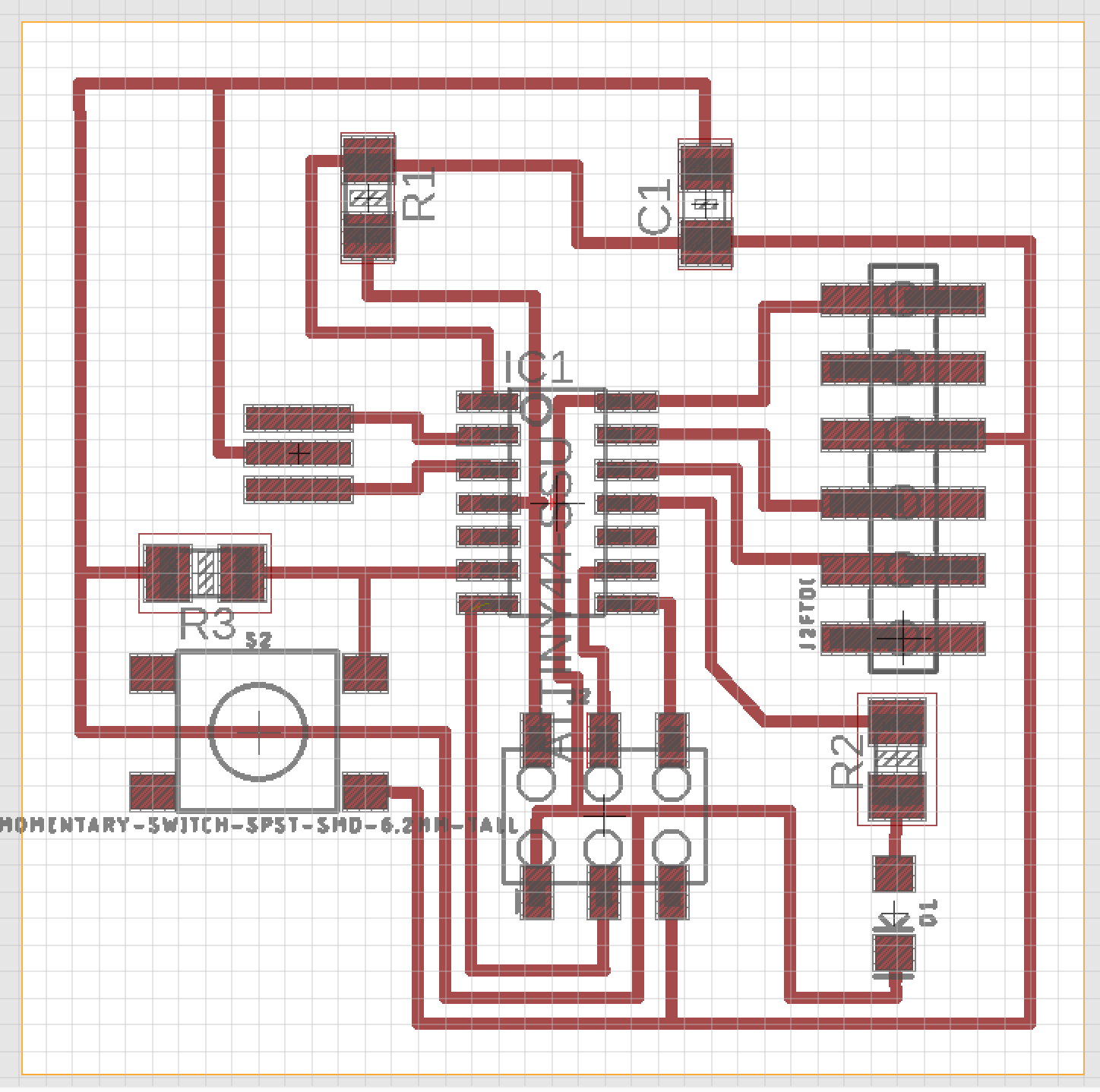
Traces exported from Eagle and cleaned up in Illustrator
Cutting paths calculated
Milled board
Soldered board
Then I burned it with the bootloader, as above, and programmed it with a standard Arduino button sketch:
/*
  Button

  Turns on and off a light emitting diode(LED) connected to digital pin 13,
  when pressing a pushbutton attached to pin 2.

  The circuit:
  - LED attached from pin 13 to ground
  - pushbutton attached to pin 2 from +5V
  - 10K resistor attached to pin 2 from ground

  - Note: on most Arduinos there is already an LED on the board
    attached to pin 13.

  created 2005
  by DojoDave <http://www.0j0.org>
  modified 30 Aug 2011
  by Tom Igoe

  This example code is in the public domain.

  http://www.arduino.cc/en/Tutorial/Button
*/

// constants won't change. They're used here to set pin numbers:
const int buttonPin = 7;     // the number of the pushbutton pin
const int ledPin =  2;      // the number of the LED pin

// variables will change:
int buttonState = 0;         // variable for reading the pushbutton status

void setup() {
  // initialize the LED pin as an output:
  pinMode(ledPin, OUTPUT);
  // initialize the pushbutton pin as an input:
  pinMode(buttonPin, INPUT);
}

void loop() {
  // read the state of the pushbutton value:
  buttonState = digitalRead(buttonPin);

  // check if the pushbutton is pressed. If it is, the buttonState is HIGH:
  if (buttonState == HIGH) {
    // turn LED on:
    digitalWrite(ledPin, HIGH);
  } else {
    // turn LED off:
    digitalWrite(ledPin, LOW);
  }
}
As before, my LED is wired to pin 2, and my button to pin 7 (and then to VCC, so when pressed it sends a digital HIGH signal).
All works!
Testing the board with the oscilloscope
I wanted to learn how to use an oscilloscope, so I thought I’d try to get my board to produce a PWM signal and then probe that. I started by mocking it up on my Arduino.
I connected an LED to pin 9 on the Arduino headers, and uploaded the standard Fade sketch to make it pulse with a PWM signal.
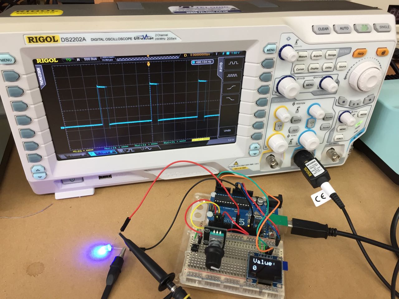
Then I tried a variant of that sketch on my Hello World board. This video shows the board getting power from a breadboard connected to an Arduino, via the FTDI header, then an LED connected to the MOSI pin on my ISP header (connected to pin 7 / PA6 on the ATTiny44).
The LED doesn’t light, and the waveform doesn’t look like the nice clean modulating square wave I got on my Arduino. I don’t yet know what the cause of the problem is: it could be the power supply from the breadboard, shorts or poor connections on my Hello World board, or something else.
Group assignment
Using the test equipment to observe the operation of a microcontroller circuit board