Week 10 - Molding and casting
Designing objects in 3D, making molds on the desktop CNC milling machine, and casting parts.
3D Object Design
I decided to make a small bowl with a fitting lid. I used Fusion 360 to model the parts.
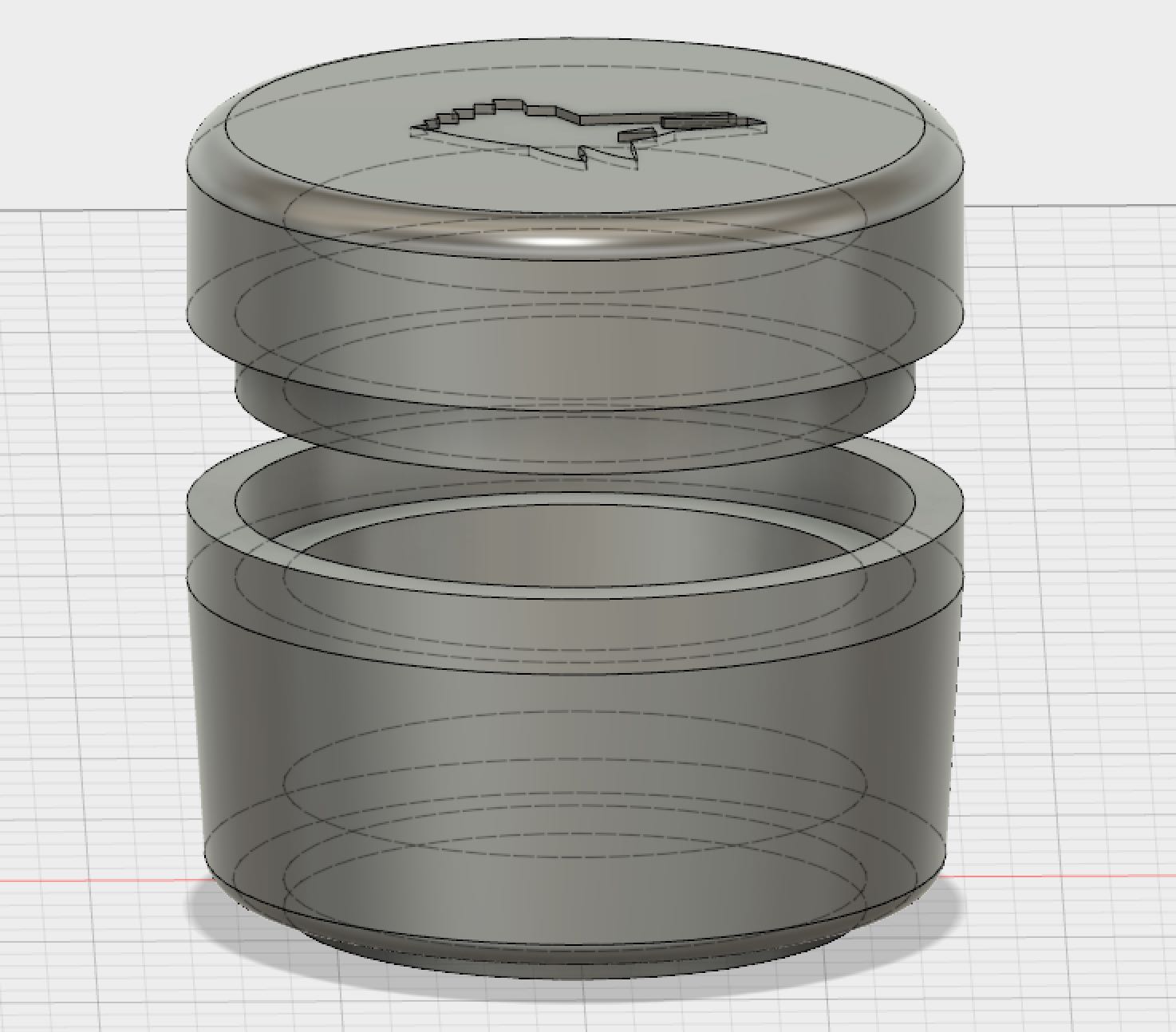
My plan was to make this out of a plaster-type material, taken from a flexible silicon 2-part mold, which in turn would be cast from a modelling wax mold cut on the milling machine.
After realising how long this would take, I decided to just make the base of the bowl, and I’ll make the lid later if I have time.
Designing the silicon mold parts
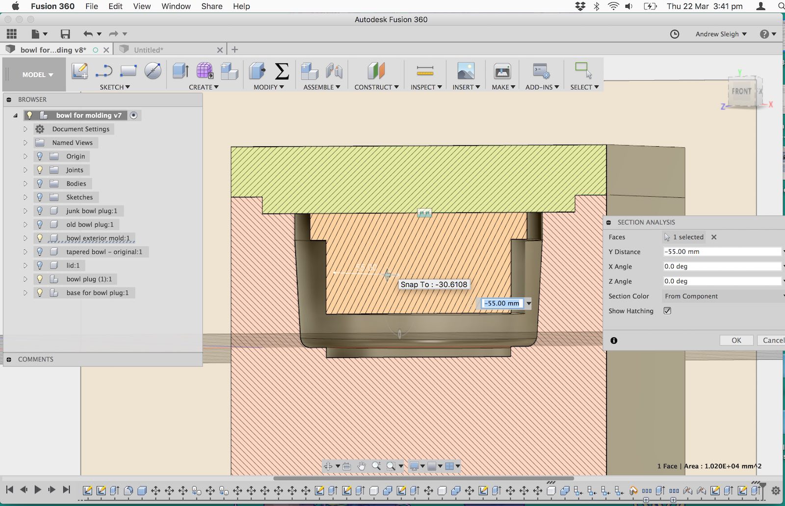
I needed a 2 part mold to cast the interior and exterior features of the part.
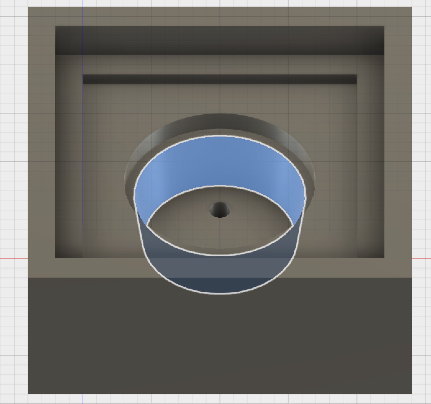
I modelled these in Fusion 360, deriving the shapes form my original part design. I designed the part for the interior mold so that it registered in a lip inside the exterior mold.
Designing the wax pre-mold parts
I then needed to design wax pre-mold parts from which I could cast these silicon molds. The interior mold part needed to have pour and vent holes added to allow the silicon to be poured in.
Mold for exterior silicon mold
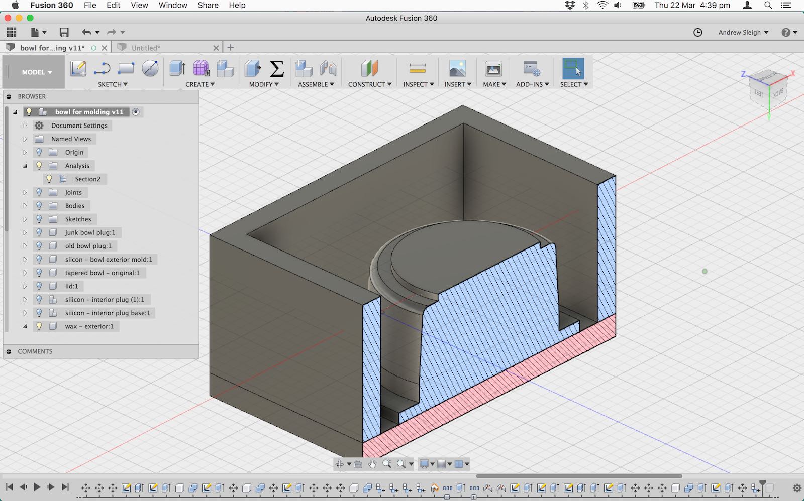
Mold for interior silicon mold
Creating milling paths for the pre-molds
I used SRP Player software to create the paths. My original cut time, using a 6mm roughing bit, and 1mm finishing bit, was 34 hours. So I had to reduce the quality settings, and instead use a square nose 6mm for all paths.
I originally tried to use the ball nose bit, which is much longer than the square nose bits that we have but this left me with rounded corners in problematic places in my mold:
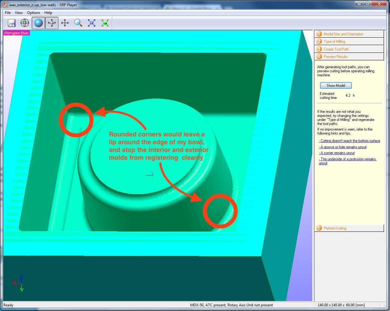
So I went back to a square nose bit, which is much shorter, and changed my design to accomodate it – I made the outside walls lower, and also tapered them, to allow more space for the tool collar.
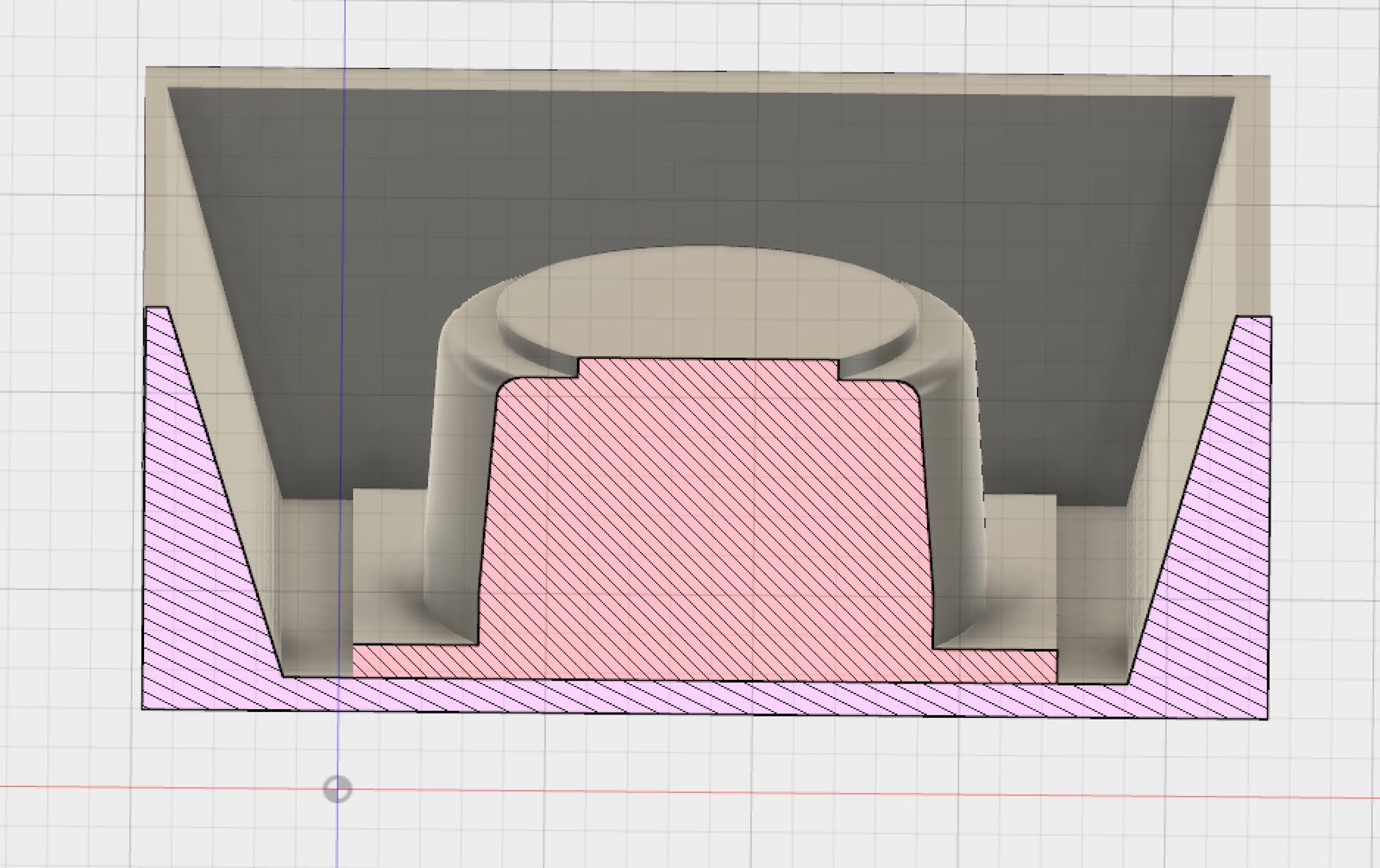
This tool will leave me with some rounded corners on the outside of my silicon mold (due ot the 6mm diameter), but I have no interior corners to worry about.
I also reduced the size of the whole model by 15% in SRP, so the height of the central bowl wouldn’t interfere with the bit. I must remember to do the same for the interior mold.
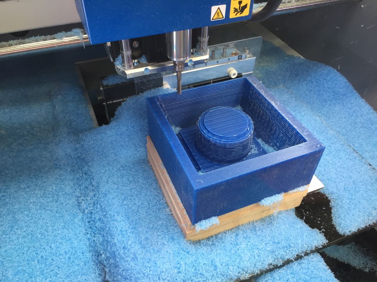
Milling the exterior wax pre-mold
Estimated cut time is 3.5 hours. My mold has a lot of empty space (= waste material) so I could look to optimise this in a future mold.
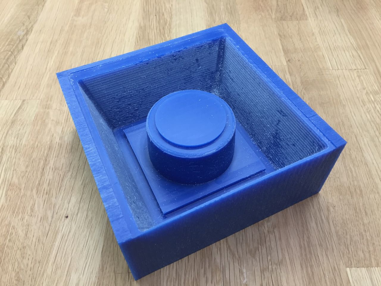
The result
Milling went according to plan, and my first pre-mold looks good.
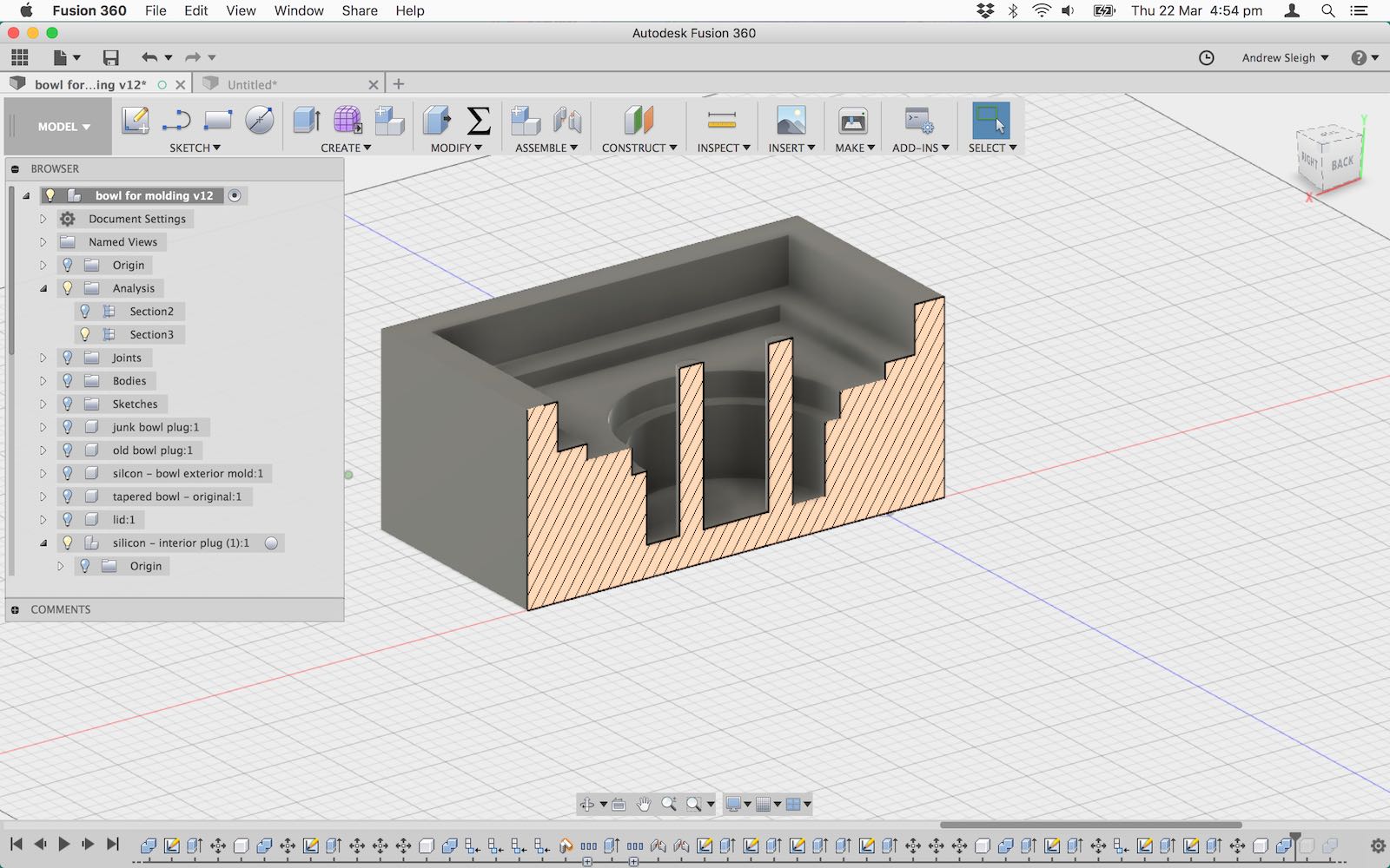
Adjusting the design for the interior pre-mold
Having learned about the constraints of the milling machine, I made some adjustments to the design for the interior pre-mold to make it easier to mill.
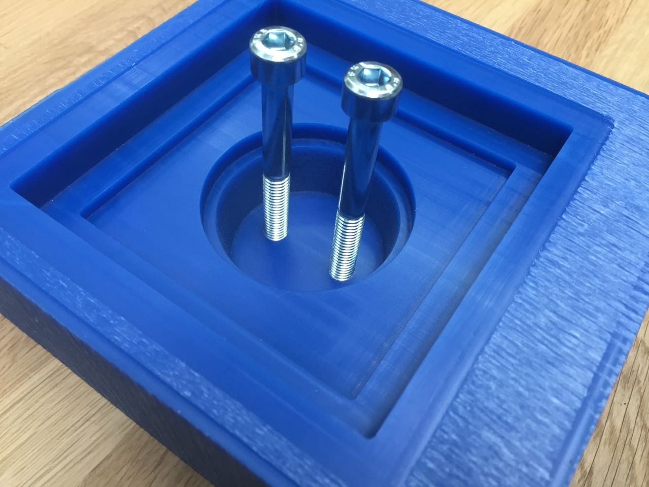
I swapped out the posts that would create holes in the silicon for hols in the pre-mold. These are easier to mill, and will not interfere with the bit. I will create posts later by simply inserting some M8 bolts into these holes. This will have the same effect of creating 8mm holes in my silicon mold for pouring and venting.
I also applied two chamfers to the internal wall, which was originally vertical. These chamfers extend to the entire height of the interior wall, effectively giving it a taper, and should allow the drill bit to reach the bottom without interference.
Milling the interior wax pre-mold
I created milling paths with the same settings as before, but this time used a 3mm square-nosed bit, for roughing and finishing.
As before, I scaled the model to 85% in the SRP Player software, to make it easier and quicker to mill.
Adding pour and vent holes.
Rather than incorporating pillars into my pre-mold, to form pour and vent holes in the silicon mold, I just made some 8mm holes in the design, and screwed in M8 bolts to form the pillars.
Making the silicon molds
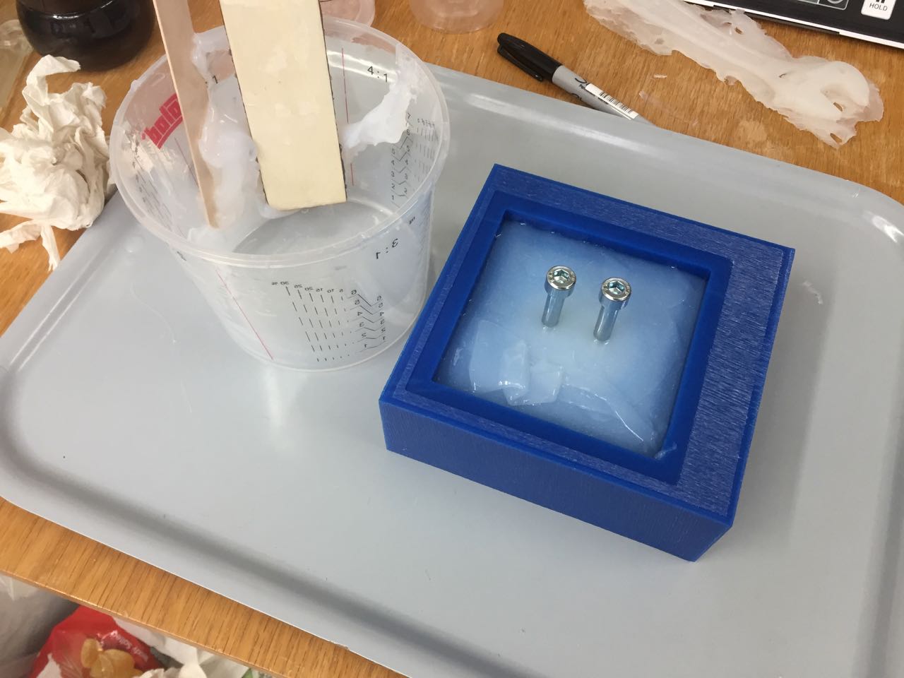
I used a 50:50 mix of Polycraft T-20 Translucent Silicon Rubber.
This has a working time of only 3 minutes, so I had to be quick in mxingand pouring my silicon.
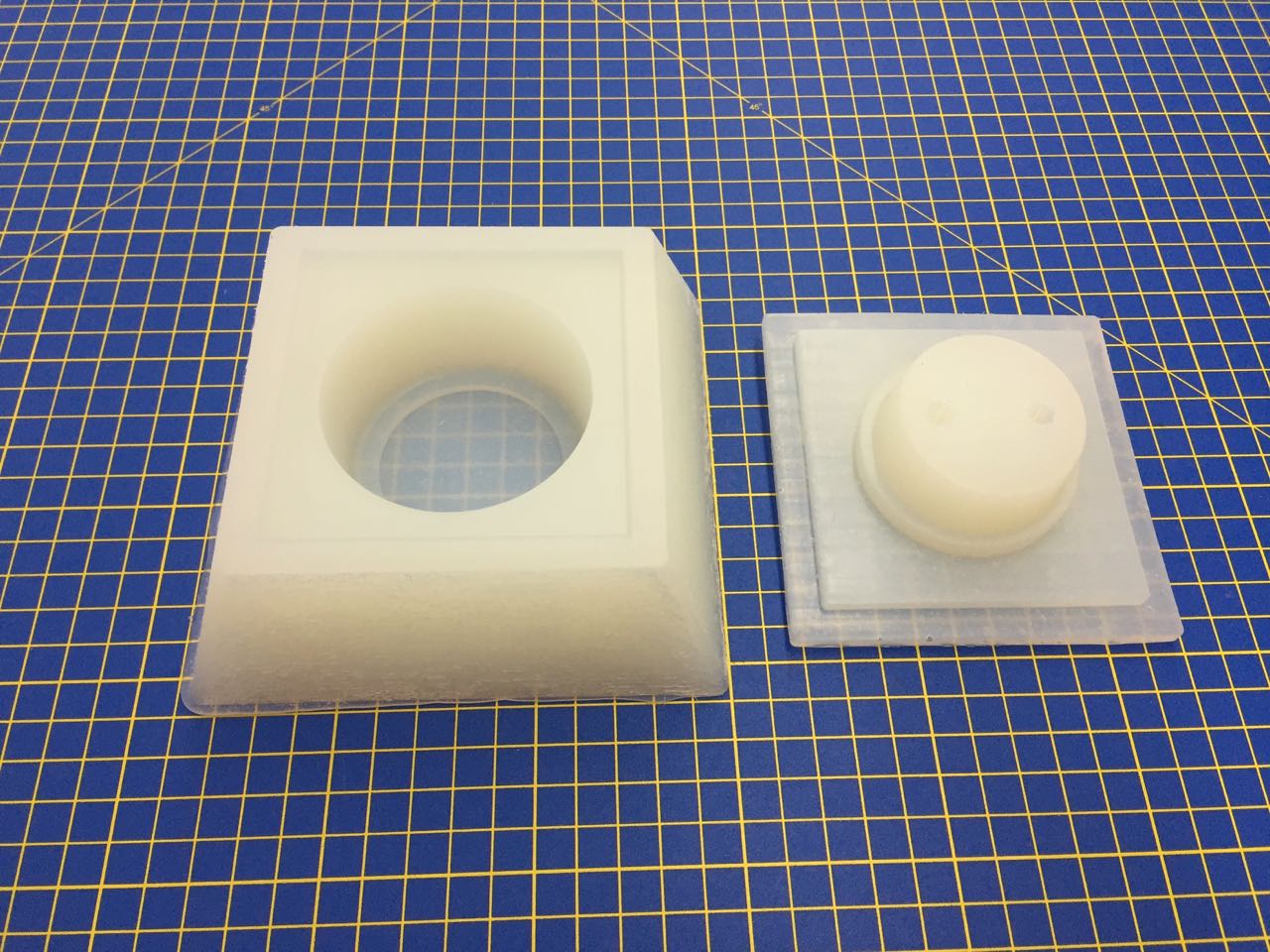
Both molds turned out well, though once assembled, I realised the pour holes were in the wrong place. I may need to drill an extra hole for venting.
Then I tried casting some test objects with powder we have in the lab. For my first test I used a 2:1 mix of pwder to water. This was too thick to pour easily.
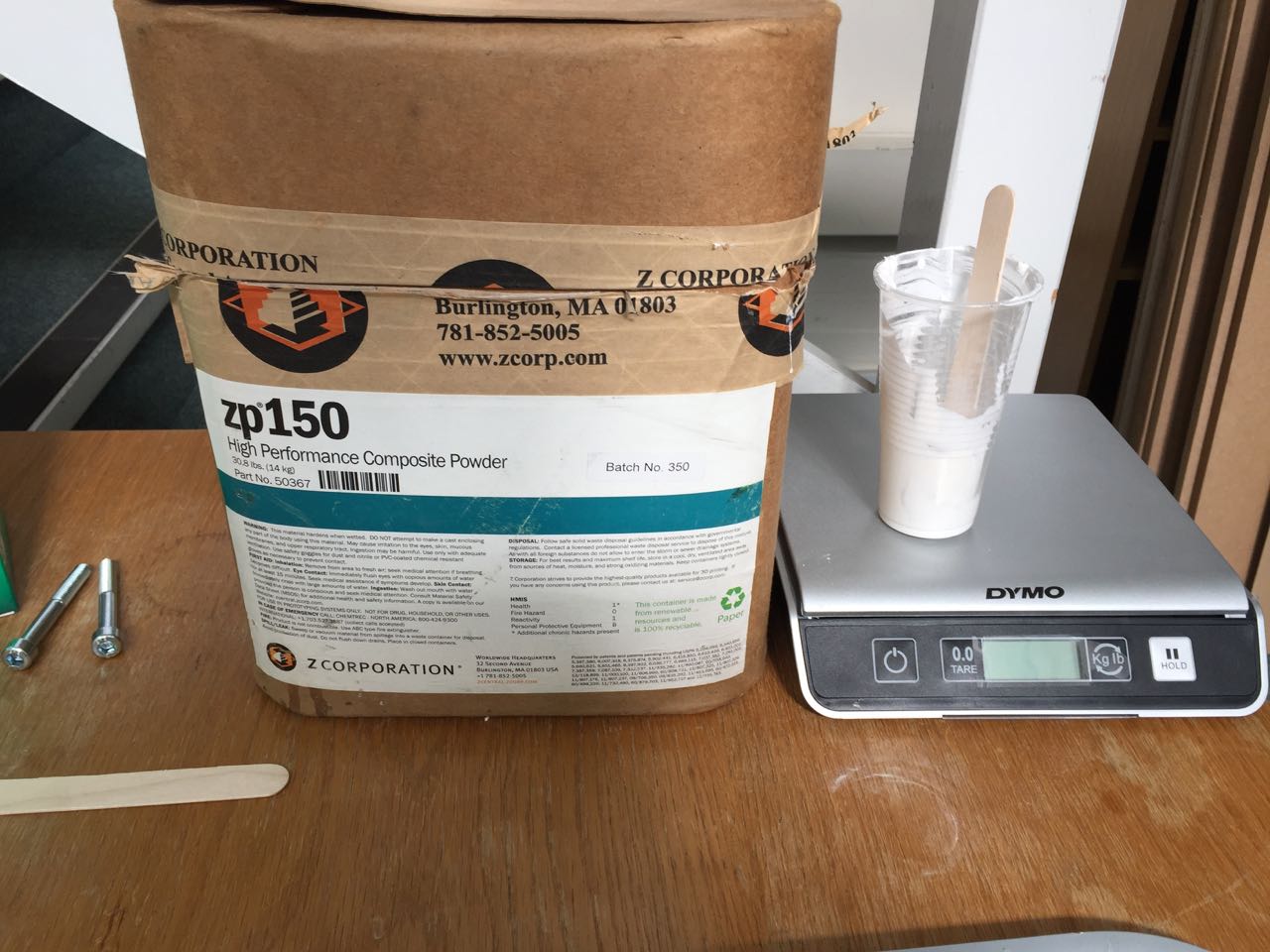
It cast OK in this one part mold, but even here, you can see some voids in the part.
Casting in plaster
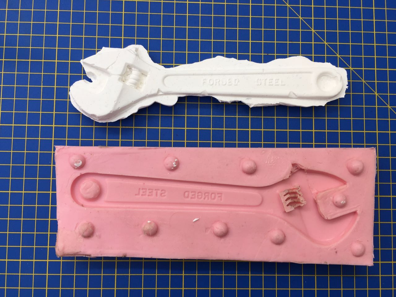
I did another test with casting plaster in the wrench mold, using a 1.3:1 mix of plaster to water
This worked pretty well, so I tried casting my own part.
I measured to volume of liquid needed to fill the cavity: 70ml. So I mixed 80ml of plaster
- 45g plaster powder
- 35g water
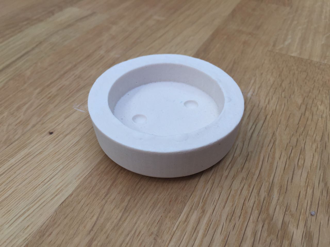
This didn’t fill the cavity, but a larger mix of 65g plaster powder and 50g water worked OK.
Casting in resin
Then our order of resins arrived, so I could move on to that. First, I tried a cast using Smooth-On Smooth-Cast 326 EU, with a little pigment added. This has a long mix time of 7-9 minutes, so is much easier to work with than the silicon I used for the molds.
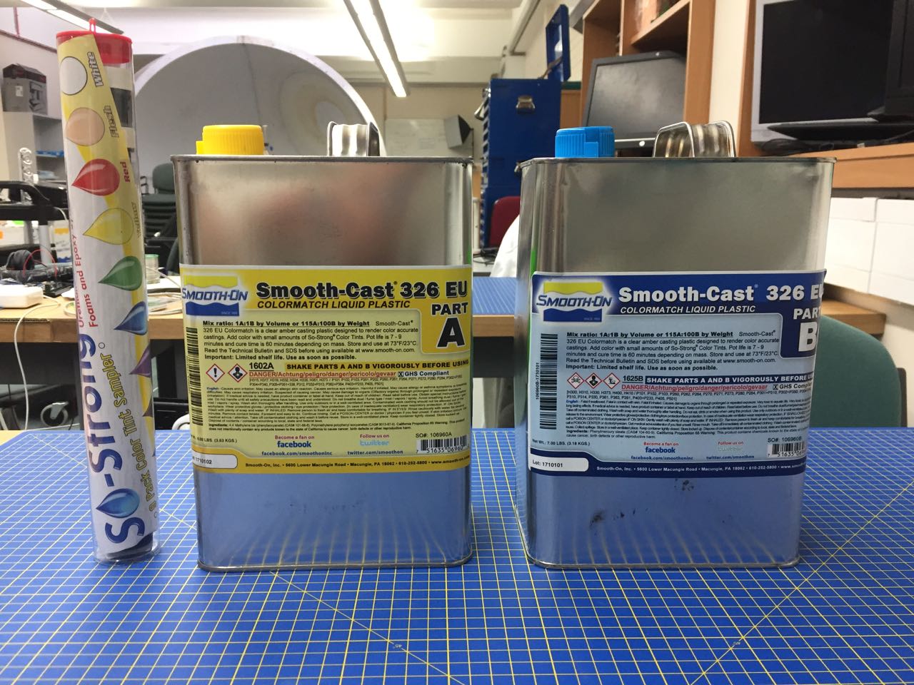
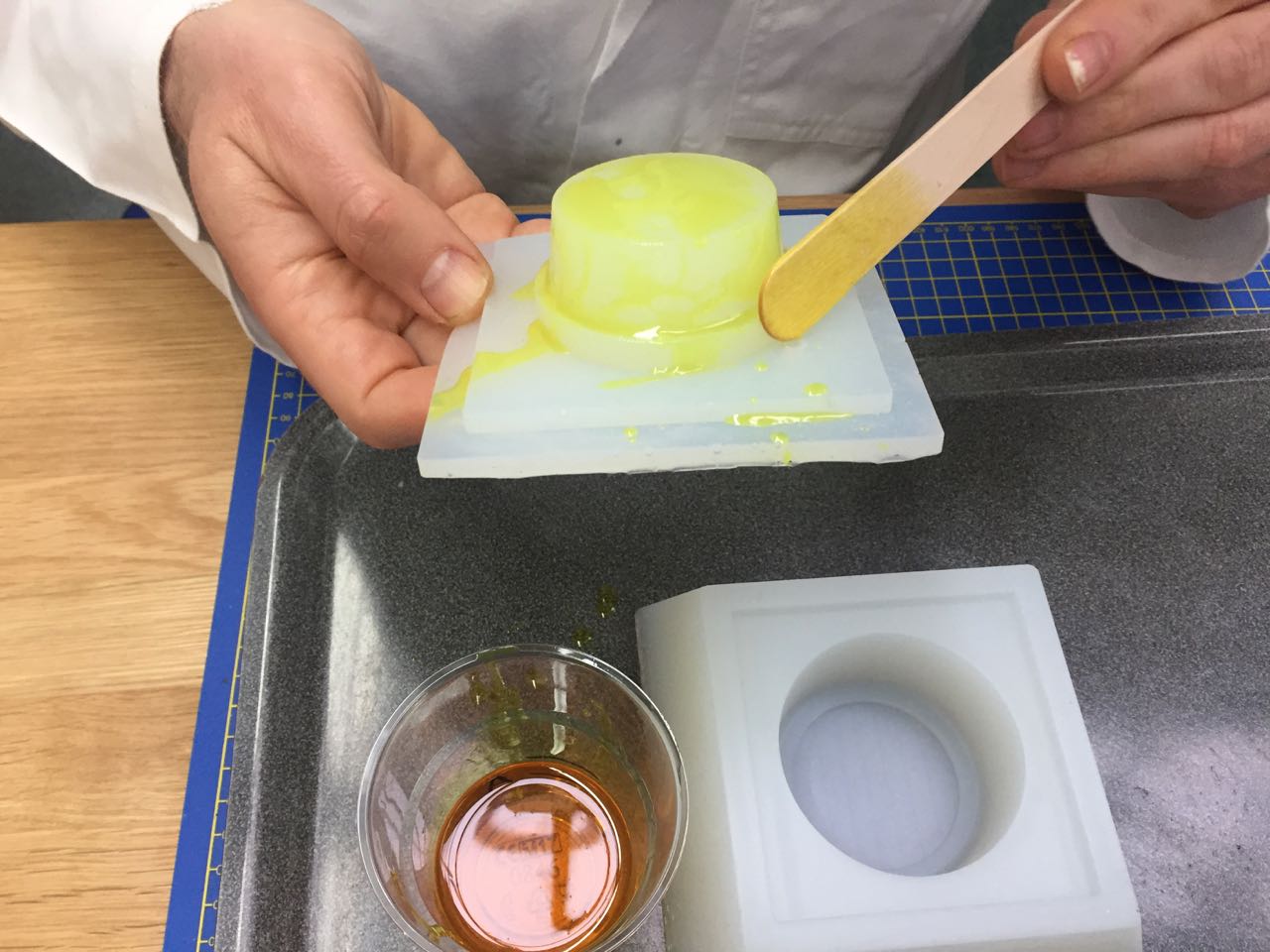
I tried painting the resin onto the mold before assembling the mold parts to get a better surface finish, and reduce the likelihood of air bubbles on the surface.
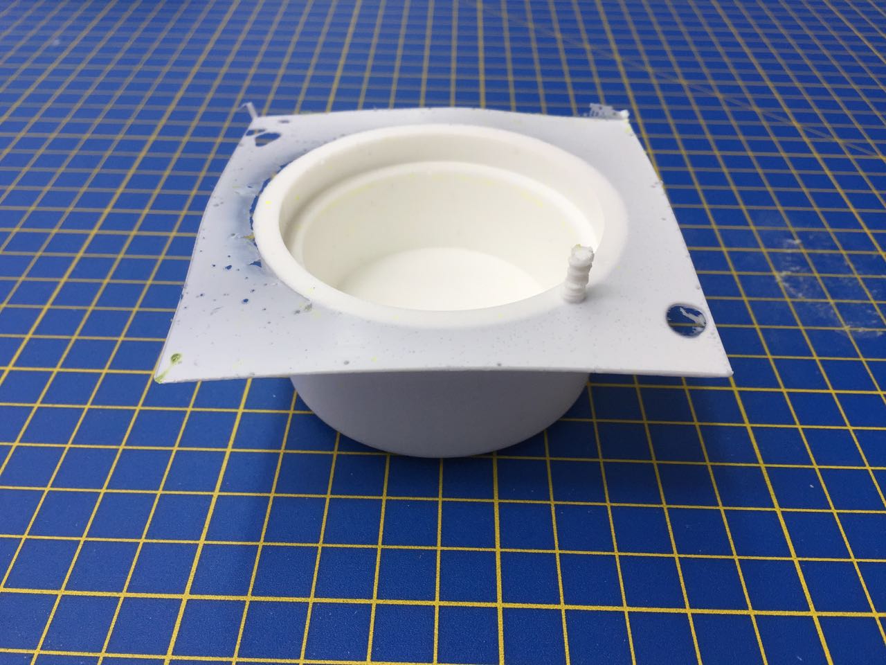
I also plugged my two redundant pour and vent holes with a fresh mix of silicon, and drilled a new hole in the top part to allow me to vent and pour if necessary – though I intended this mold to work by squeezing the two parts together, allowing any excess to escape around the sides, and be removed later.
Again, though I had mixed too little, and the mold had not filled.
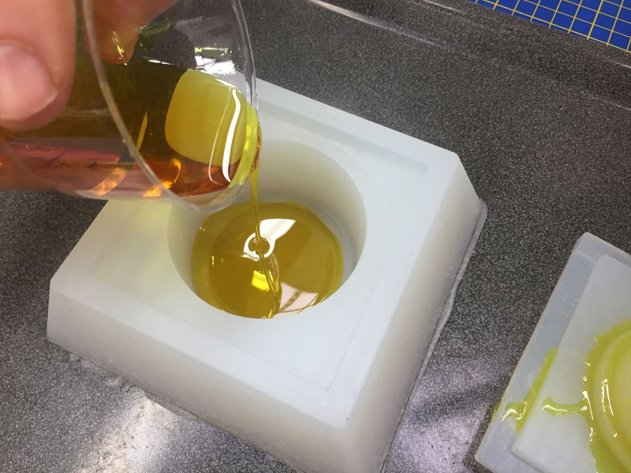
Next, I tried Smooth-On Smooth-Cast 305, another clear 2 part resin. This time I was generous with my quantities.
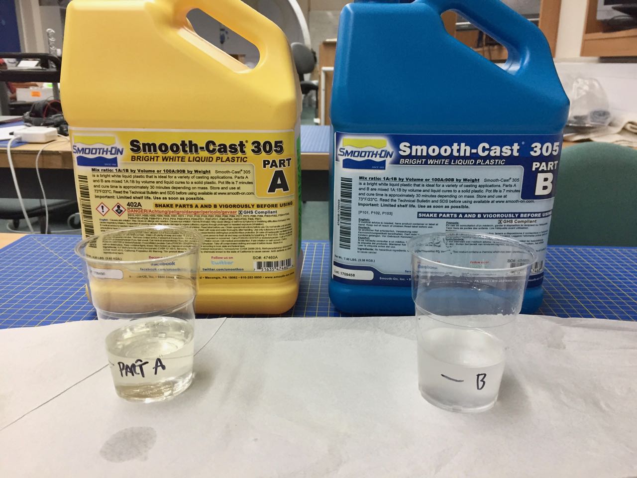
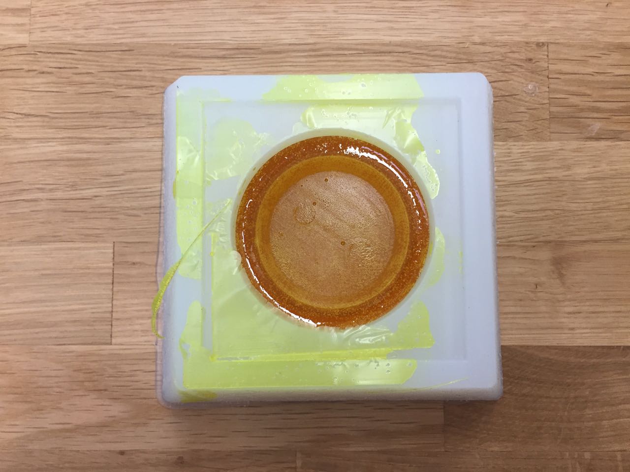
I used the same molding technique of filling the cavity, then inserting the plug, allowing excess resin to escape through the gap, and out of the new vent hole in the top. It was easy to trim this excess once the resin had cured.
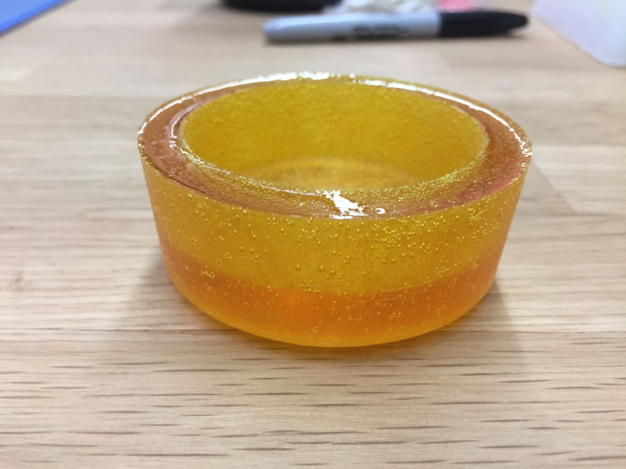
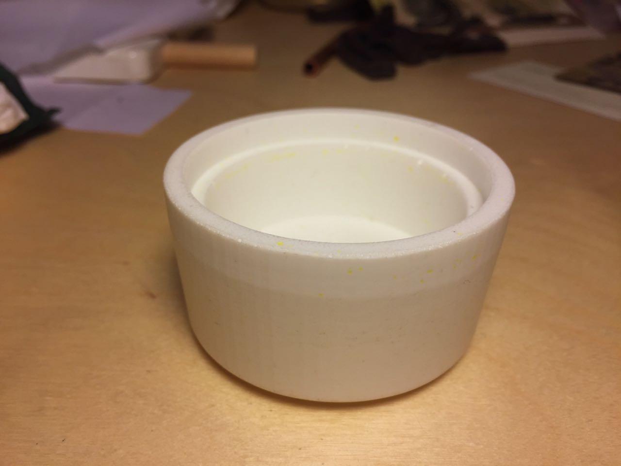
This cleaned up nicely to a finished part
Group Assignment
We reviewed the safety data sheets for each of our molding and casting materials, then made and compared test casts with each of them.
Files
- Link to Fusion 360 file in public cloud: https://a360.co/2JxYktJ
- Direct download