Week 12 - Output Devices
I made a second version of my input devices board, with a simplified design, and a header set up for I2C communication with an OLED display.
Improving my input devices board
After my experience with the previous board, I decided to fix some of its shortcomings:
1) I wanted to get rid of the external pull-up resistors on my 20 pin header. According to the data sheet, pins on ports B, C, D and E all have internal pull-up resistors, which can be turned on by adding a line like this in your Arduino code:
void setup() {
  /* INPUT_PULLUP enables the Arduino Internal Pull-Up Resistor */
  pinMode(12, INPUT_PULLUP);
}
On this header, the first 2 switches are connected to port F pins, which do not seem to have internal pullups. However, I was able to shift my pins around to make use of pins 21 and 22 on this 20-pin header instead, which are both port D pins.
I was then able to remove all these pull-up resistors from the board, and also the GND trace that ran all the way over to that side of the board adding more size and complexity.
2) I swapped out my 16MHz crystal for one with the correct footprint, and rearranged the components around it to fit better.
3) The D+ and D- lines from my USB port to the ATMega32U4 have to travel underneath a capacitor. The narrow gap is forcing my traces to be very thin, and possibly causing problems with signal from the USB port.
Looking at Luiz’ original board - from which mine is derived, I noticed that:
- there are 22Ohm resistors on each of these traces, which I have omitted from my board
- he has bridged different GND and VCC pins on the ATMega32U4, meaning he doesn’t need to have these two traces running underneath a decoupling capacitor.
4) Sorting out my decoupling capacitors: I have 8 decoupling capacitors in my original design, however, there are only 5 GND pins (including UGND) and 6 VCC pins (VCC x 2, AVCC x 2, VBUS and UVCC)
So I should be able to simplify things here.
An explanation of each of these pins:
The 2 AVCC are used to power the Analog circuitry, and not connecting them, and not filtering it, would mean shitty analog to digital or digital to analog conversions. If you don’t need the ADC or DAC features it’s not mandatory.
The VCC powers the digital circuitry. You should connect both. YMMV if you don’t. Drawing too much power cab cause issues then.
The UVCC is for powering the USB circuitry. Again if you don’t use it…
VBUS is actually an input that connects to USB power, for sensing when a usb cable is connected.
I see I have one capacitor not connected to any VCC net, and another capacitor connected to AREF. Both of these can be removed.
5) I have to rearrange my spare pin headers now that I have swapped around the pins on the main 20x header.
I now have 3 spare pins on the bottom side of the chip (18, 19, and 20) and 7 on the top (L-R: 42, AREF, 41, 40, 39, 38, 37, 36), plus up to 2 GND pins I could expose on headers. I could also expose pin 1 on the top left corner of the chip to a header along the top.
New header pin tables
These are my new header configurations
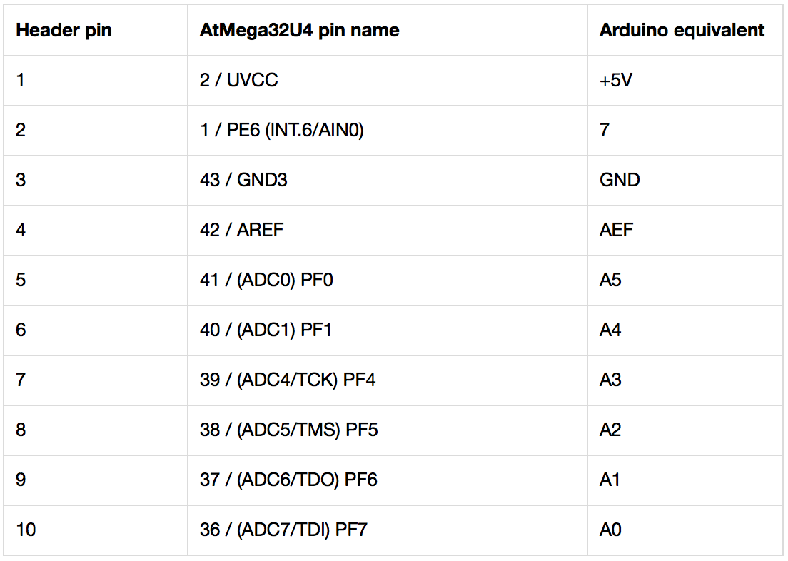
Header A: 20 pins, to right of chip, reading top-bottom

Each alternating odd-numbered pin (1, 3, 5, 7, 9, 11, 13, 15, 17, 19) connects to VCC
Header B: 10 pins, above chip, reading L-R
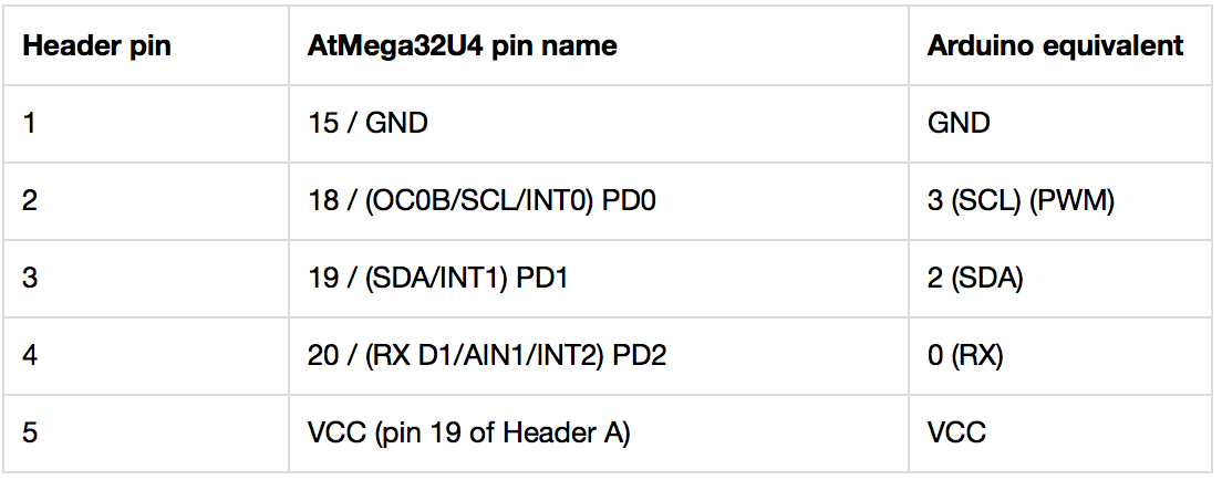
Header C: 5 pins, below chip, reading L-R
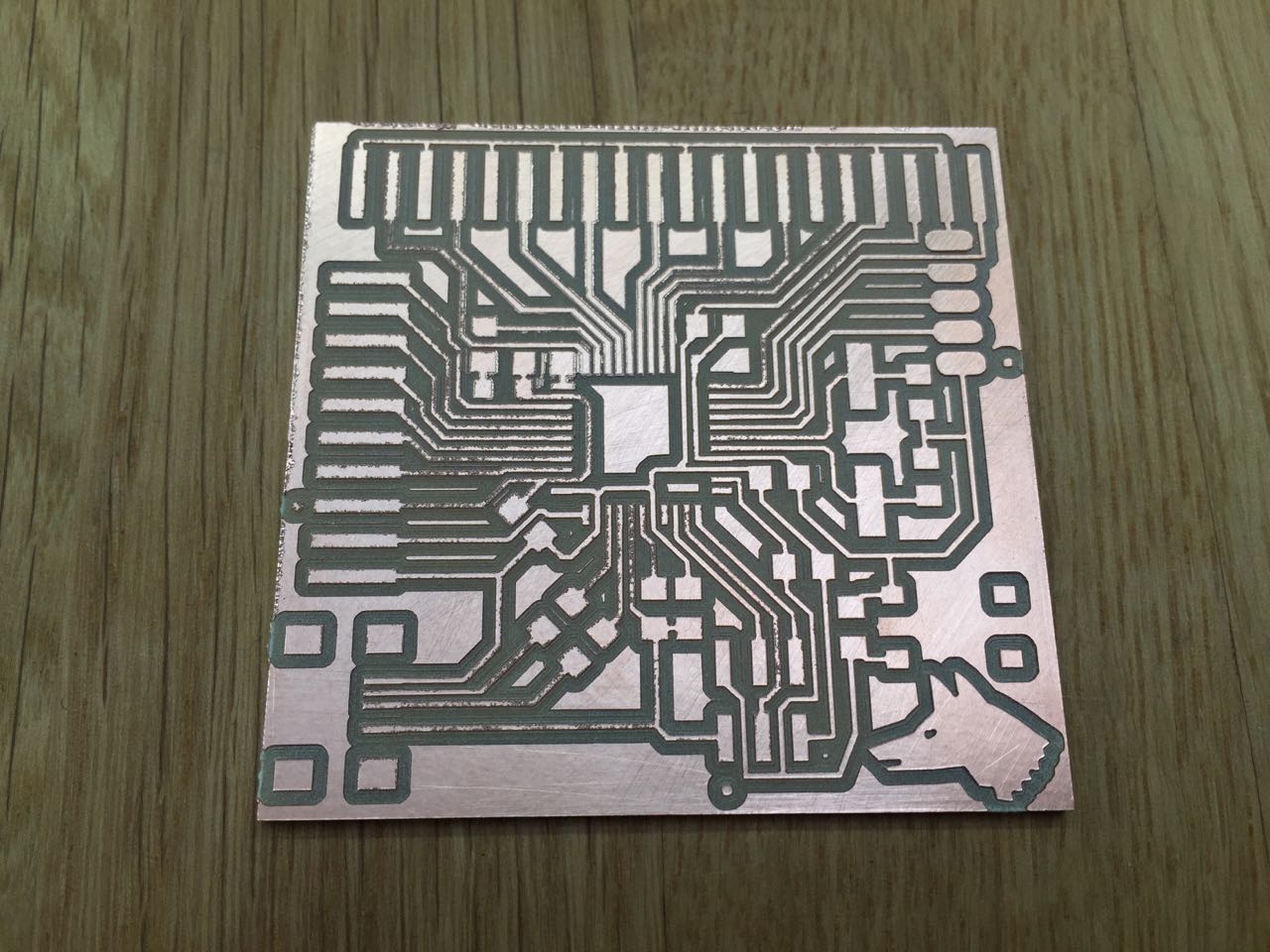
Milling and soldering the board
I was able to mill the board and solder the parts without too many problems
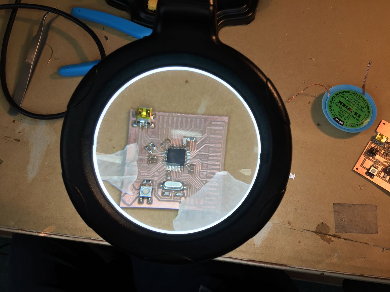
Testing
After failing to burn the bootloader using my FabISP, I checked the board for problems and found a couple: two GND pins on the chip were not connected, and a piece of stray copper was shorting the RST and VCC pins on the ISP header. After fixing these, I was able to burn the bootloader, remove the IFabISP, and upload a blink sketch over USB to blink the onboard LED I put on pin PC7 / D13.
I was also able to verify that my reset button works.
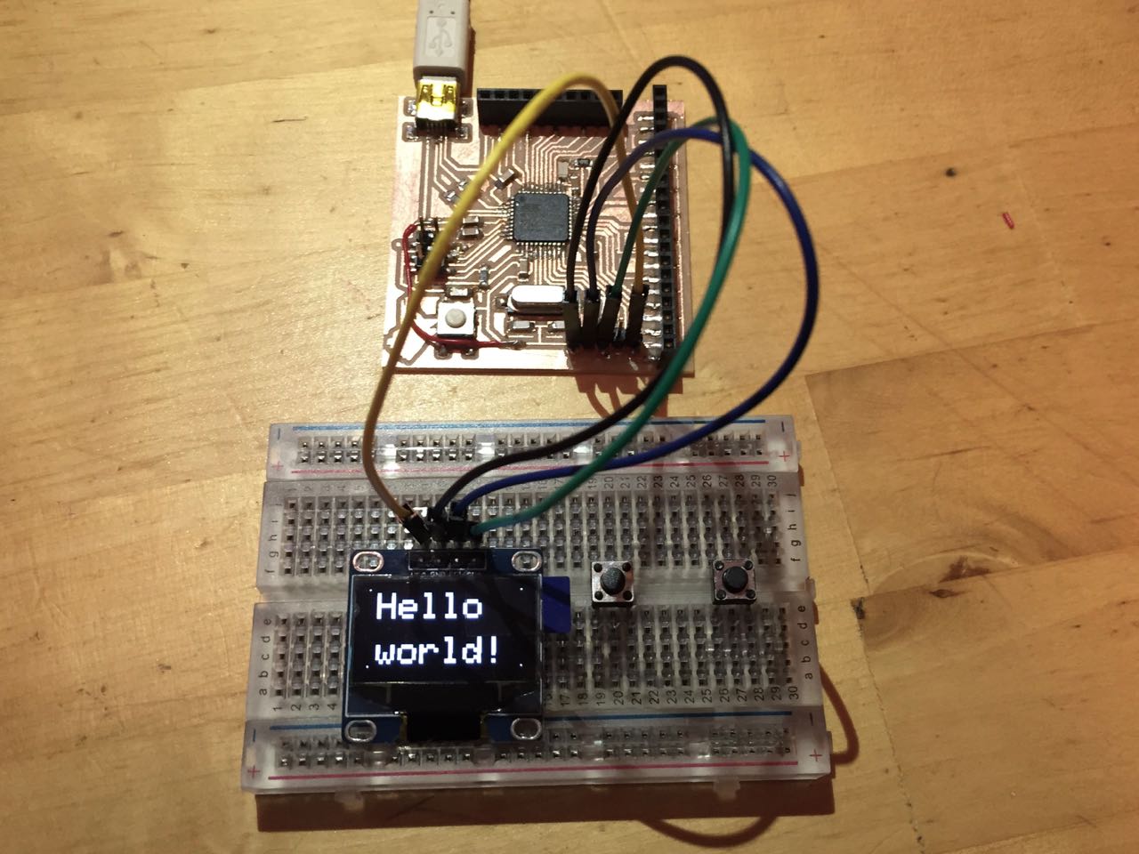
OLED Hello World
Then I set about getting my OLED panel to work. I followed these instructions.
I had set up my small 5-pin header specifically to enable easy connection of an OLED display, as follows:
Display pins -> Header pins
1) VCC -> Header pin 5
2) GND -> Header pin 1
3) SCL -> Header pin 2
4) SDA -> Header pin 3
I then installed the Adafruit Arduino libraries for controlling these SSD1306 displays
I configured the SSD1306 driver for my display, as per the instructions:
Open the Adafruit_SSD1306 folder that was just installed in the Arduino libraries folder. Find Adafruit_SSD1306.h and open it in a text editor. Scroll down the file to find the section with the header SSD1306 Displays or search for for this term in the text editor to find it quickly. Comment out #define SSD1306_128_32 and uncomment #define SSD1306_128_64 so that the code in this section looks as follows.
/*=========================================================================
    SSD1306 Displays
    -----------------------------------------------------------------------
    The driver is used in multiple displays (128x64, 128x32, etc.).
    Select the appropriate display below to create an appropriately
    sized framebuffer, etc.

    SSD1306_128_64  128x64 pixel display

    SSD1306_128_32  128x32 pixel display

    SSD1306_96_16

    -----------------------------------------------------------------------*/
   #define SSD1306_128_64
//   #define SSD1306_128_32
//   #define SSD1306_96_16
/*=========================================================================*/
I uploaded a basic Hello World Sketch to verify my board and OLED panel worked.
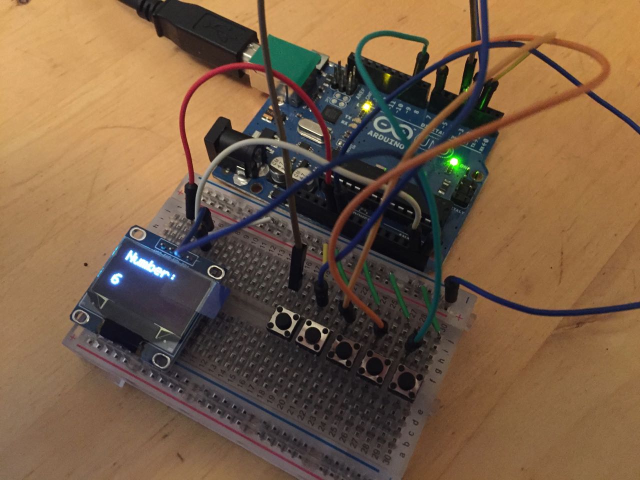
Reading an array of buttons and displaying the result
Now I was ready to prototype my input and output problem: to read the state of an array of buttons simultaneously, convert that state to a human-readable number, and display the result on a screen.
This is one step towards having a media card reader that can identify which card has been inserted and choose the right media to play as a result.
I had 5 buttons available, one of which I reserved as an ‘initiate read’ button. That left me 4 buttons, letting me generate a 4 byte binary number (e.g. 0010, 1111, 1001, etc), which would translate to decimal values 0-15.
I looked up the maths I would need to convert binary number to decimal, which is of this form:
1011 = (1 × 2³) + (0 × 2²) + (1 × 2¹) + (1 × 2⁰) = 11
So I knew I would need to loop through an array of the values of each button, do some maths on each value, and add up the individual results to store in a running total. Once I’d been through the array, I could print this total to the OLED screen.
My Arduino code:
// set up array
int arrayTest[] = {0, 0, 0, 0};       // an array of pin numbers to which LEDs are attached
int arrayCount = 4; // size of array, ie number of buttons I have available
int tempTotal = 0; // a number to hold total value in
int pushButton1 = 5; // a button to initiate the loop through the array - modified for my Output Devices board

// set up array population buttons
// I only have 4 buttons, so it will have to be a 4 byte number (ie values 0-15).

//

int arrayValueButton1 = 12; // pins which each button is connected to, reading left to right
int arrayValueButton2 = 6;
int arrayValueButton3 = 8;
int arrayValueButton4 = 9;

// set up defaults for array values
int arrayValue1 = 0;
int arrayValue2 = 0;
int arrayValue3 = 0;
int arrayValue4 = 0;


// Set up OLED display
// Based on https://startingelectronics.org/tutorials/arduino/modules/OLED-128x64-I2C-display/
// On Arduino Uno, SCL pin is A5, SDA is A4

#include <Wire.h>
#include <Adafruit_SSD1306.h>
#include <Adafruit_GFX.h>
#define OLED_ADDR   0x3C // OLED display TWI address
Adafruit_SSD1306 display(-1);
#if (SSD1306_LCDHEIGHT != 64)
#error("Height incorrect, please fix Adafruit_SSD1306.h!");
#endif

//End OLED

void setup() {


  // initialize serial communication at 9600 bits per second:
  Serial.begin(9600);


  // set up buttons to use internal pullup resistors, which menas that thier on/off values are swapped
  pinMode(pushButton1, INPUT_PULLUP);
  pinMode(arrayValueButton1, INPUT_PULLUP);
  pinMode(arrayValueButton2, INPUT_PULLUP);
  pinMode(arrayValueButton3, INPUT_PULLUP);
  pinMode(arrayValueButton4, INPUT_PULLUP);


  // initialize and clear display
  display.begin(SSD1306_SWITCHCAPVCC, OLED_ADDR);
  display.clearDisplay();
  display.display();

  // display a pixel in each corner of the screen
  display.drawPixel(0, 0, WHITE);
  display.drawPixel(127, 0, WHITE);
  display.drawPixel(0, 63, WHITE);
  display.drawPixel(127, 63, WHITE);

  // update display with all of the above graphics
  display.display();

}

void loop() {

  // read the value of the 'start' button
  int buttonState1 = ! digitalRead(pushButton1); // use ! to invert button state

  if (buttonState1 == 1) { // only read the array if the button has been pressed

    // reset the total in case we read it previously
    tempTotal = 0;

     // read the array value buttons:
      int arrayValue1 = ! digitalRead(arrayValueButton1); // use ! to invert button state
      int arrayValue2 = ! digitalRead(arrayValueButton2);
      int arrayValue3 = ! digitalRead(arrayValueButton3);
      int arrayValue4 = ! digitalRead(arrayValueButton4);

    // stick them into an array
      int arrayTest[] = {arrayValue1, arrayValue2, arrayValue3, arrayValue4};

    // loop through that array to read them
      for (int thisArrayMember = 0; thisArrayMember < arrayCount; thisArrayMember++) {


        // which member of the array (0, 1, 2, 3... up to max number of members), reading left to right
        // note, later on this will be reversed - when counting, numbers to the left have a higher value, so it's more useful to have a scale that reads L-R: 3, 2, 1, 0)
        Serial.print("Member: ");Serial.print(thisArrayMember);

        // what's the value of that member (0 or 1)
        Serial.print(" | Value: ");Serial.print(arrayTest[thisArrayMember]);

        // what's 2 to the power of the position of the member
        // use ceil() to ensure numbers are rounded correctly
        // reverse position numbers (arrayCount - thisArrayMember) so numbers to the left are multiplied more
        // reduce thisArrayMember by 1: to correct for error introduced because arrayCount ranges 1-4, thisArrayMember ranges 0-3
        Serial.print(" | 2 to power of position of member: ");Serial.print(ceil(pow(2, (arrayCount - thisArrayMember - 1))));

        // Multiply that value by the value of the button (1 or 0)
        Serial.print(" | Value x 2 to power of position: ");
        Serial.print(int(arrayTest[thisArrayMember] * ceil(pow(2, (arrayCount - thisArrayMember - 1)))));

        // and print the running total of all these values added up
        Serial.print(" | Running total: ");
        tempTotal = (tempTotal + arrayTest[thisArrayMember] * ceil(pow(2, (arrayCount - thisArrayMember - 1))));
        Serial.println(tempTotal);


         tempTotal = (tempTotal + arrayTest[thisArrayMember] * ceil(pow(2, (arrayCount - thisArrayMember - 1))));


    } // end array loop

        //  display final result on OLED display
        display.setTextSize(2);
        display.setTextColor(WHITE);
        display.setCursor(7,3); // line 1
        display.print("Number: ");
        display.setCursor(7,40); // line 2
        display.print(tempTotal);

        display.display(); // update display with all of the above graphics
        display.clearDisplay(); // clears the buffer so it can be rewritten with new values when they arrive - doesn't clear the screen

  }

}
After many hours of breaking down the problem, and squashing bugs, it finally worked:
Some questions and problems
While I get this far, the process has led to new questions, and revealed some problems with my board
-
For my large 20 pin header, I intended to leave each alternate pin accesible for all the connected buttons. I wired all these pins to VCC. Actually, given that the ATMega32U4 has internal pullup resistors, I should have connected them to GND. So in this case, I didn’t use them, and instead, made use of one of the other GND pins I had exposed to a pin (as recommended by Luiz. It makes me think that actually, having 10 identical pins available, even if they are wired up correctly is probably not much use.
-
The OLED display uses I2C communication. I don’t know if i will also need to use this for some other parts of my final project, and if so, will there be a conflict.
-
When testing on my board, and also on a commercial Arduino board, I noticed some memory alerts. On the Arduino, with all my serial debugging code, the programme above uses 79% of program memory. With the serial code commented out it uses 64%. And on my homebrew Leonardo board, it uses 57$% (again, without debugging code). Maybe this will cause problems later on.
-
I noticed that not all of the pins on my dedicated ‘button header’ (the 20 pin header) worked. When I have access to more button hardware, and when I’m ready to connect up other parts of my system, such as the MP3/SD card reader, and playback controls, I need to verify that I can get all these to work. I could also try using a PISO shift register to reduce the number of pins needed for this part of the system. From an earlier code test, these were the pins that worked/didn’t work:
int pushButton = HWB; // header pin 2- DOESNT WORK
int pushButton = 5; // header pin 4 - WORKS
int pushButton = 6; // header pin 6 - DOESNT WORK
int pushButton = 9; // header pin 8 - WORKS
int pushButton = 8; // header pin 10 - WORKS
int pushButton = 6; // header pin 12 - WORKS
int pushButton = 12; // header pin 14 - WORKS
int pushButton = 4; // header pin 16 - DOESNT WORK
int pushButton = 17; // TXLED  // header pin 18  - DOESNT WORK
int pushButton = 1; // header pin 20 - WORKS
Group assignment
We used an oscilloscope to measure the power consumption of an output device - a motor.
Files
Eagle files for my board
Arduino test files