Week 10 - Moulding and casting
Group assignment
Review the safety data sheets for each of your molding and casting materials, then make and compare test casts with each of them.
Here is a link to our lab's page which includes links to all our group assignments.
Individual assignment
design a 3D mold around the stock and tooling that you'll be using, machine it, and use it to cast parts.
Assignment summary
what I achieved/learned this week:
- created a 3D logo part in Rhinoceros
- textured the part
Creating moulds is something I've not really done before, but been wanting to do for ages. The idea of combining the mould making process with the CNC milling process is exciting for me, because it allows for a very good surface finish, but also for multiple units to be made...perhaps tens of units using the basic wax or silicone materials we'll be using. My first model really does test out these capabilities.
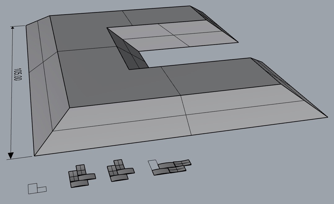
I decided to cast a logo for my final project, using skills to make an intricate mould using the two-step process where a male mould is machined from the wax, and then a rubber is poured into this to create the female mould that can then be used to make the parts. Such a clever way of doing it, but quite a struggle mentally at first! Here are some of the early cad models, I wasn't sure how deep to make the parts, but opted for the shallower option (7 mm deep x 105 mm wide) to make it quicker to machine, but also in the end I also want to make one of these 'plaques' out of carbon fibre. The idea with the cast part for this week is to make it LOOK like carbon fibre by applying a woven or at least a texture that is recognisably like that of carbon fibre.
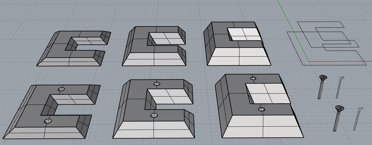
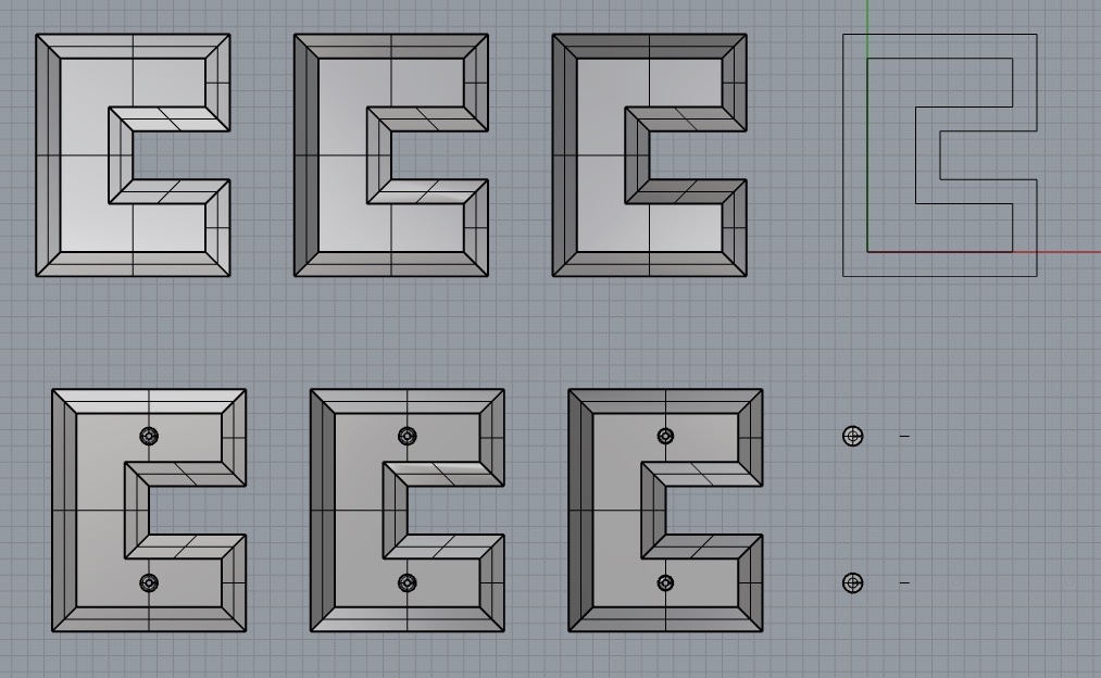
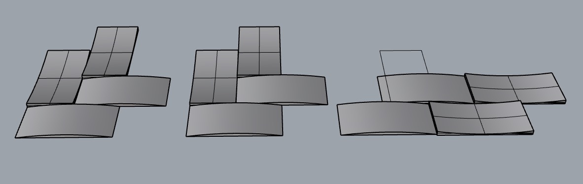
Originally the idea was to use the 'flow along surface' command in Rhinoceros to get this repeating pattern to flow along the top surface of the part, creating a real texture that can be machined out. After a little playing, there were real problems because it only really works on a single surface, and I was essentially using a poly surface with 5 surfaces in a net of the top of the part...it would be fiddly to get it to work. Here is the early CAD model for this anyway.
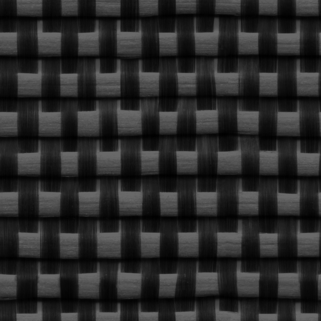
So I called on the help of a friend and colleague of mine, Ollie K who is a genius with Blender and CAD in general, and he helped me to map an image of the woven structure onto the surface, using a greyscale distortion factor to essentially pull the surface up or down an amount that depends on the greyscale value of the pixel. Clever, simple...well not that simple, I couldn't do it, I needed Ollie's help, thanks Ollie! Anyways, here's the texture image that we used in the end.
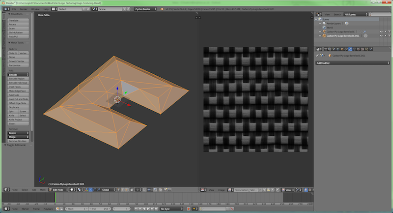
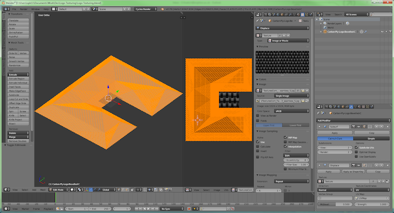
So here's how it was done in Blender. The first step was to load the .stl file (included below) and the image texture file.
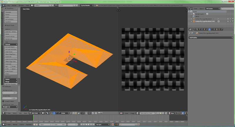
Then the mesh was subdivided to increase the mesh density.
Then the mesh was unwrapped or projected onto the image texture.
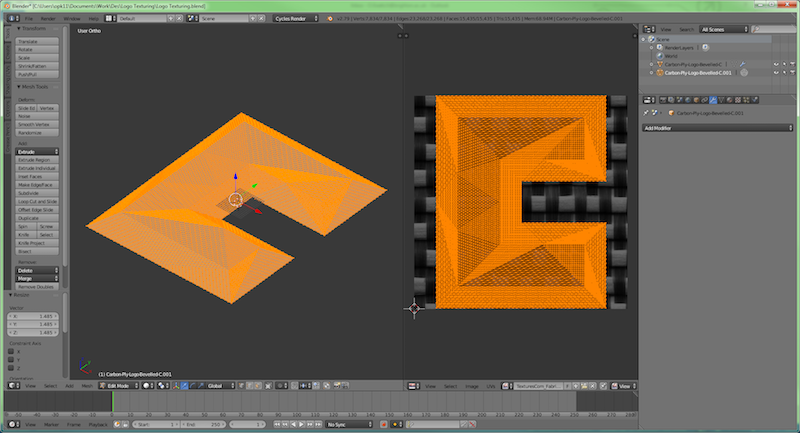
Then further subdividisions were made with displacements generated by the greyscale of the mapped image.
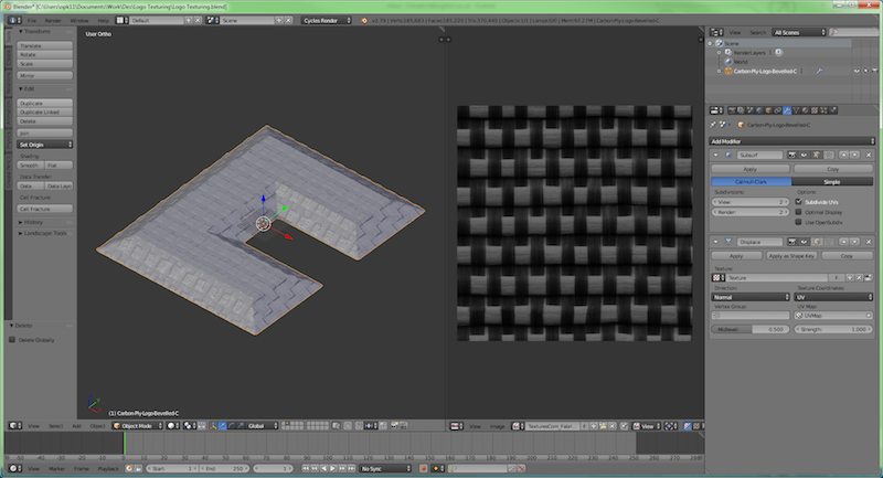
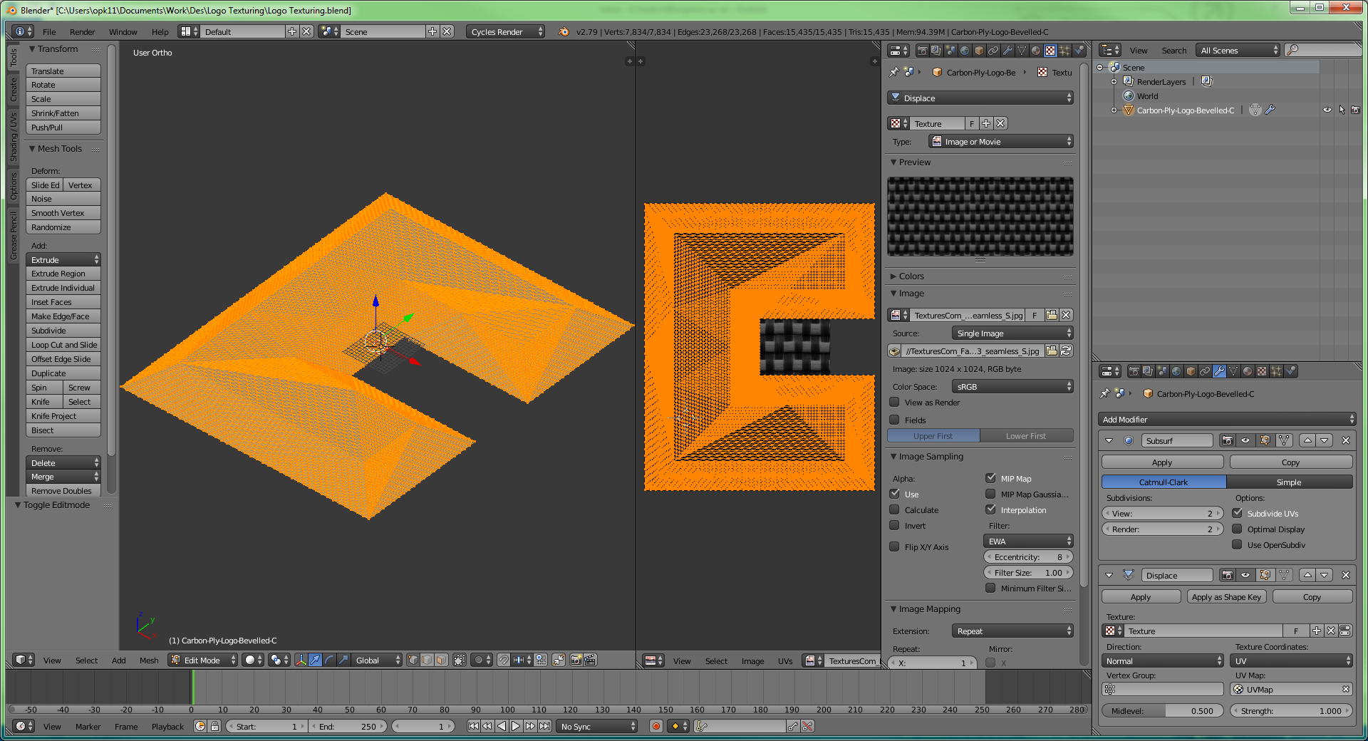
Settings can then be used to adjust the scale of this displacment.
Here are those settings up close...
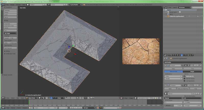
Clearly this image can be replaced with any other textural image, here's an example...here's a wood board effect.

and cracked stuff works well...
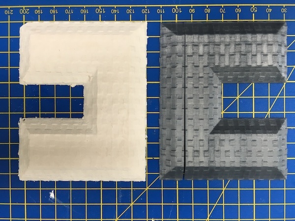
And here is the final resultant .stl mesh, with the texture applied to the CAD model and loaded into Rhino...the effect was nice!
![]()
![]()
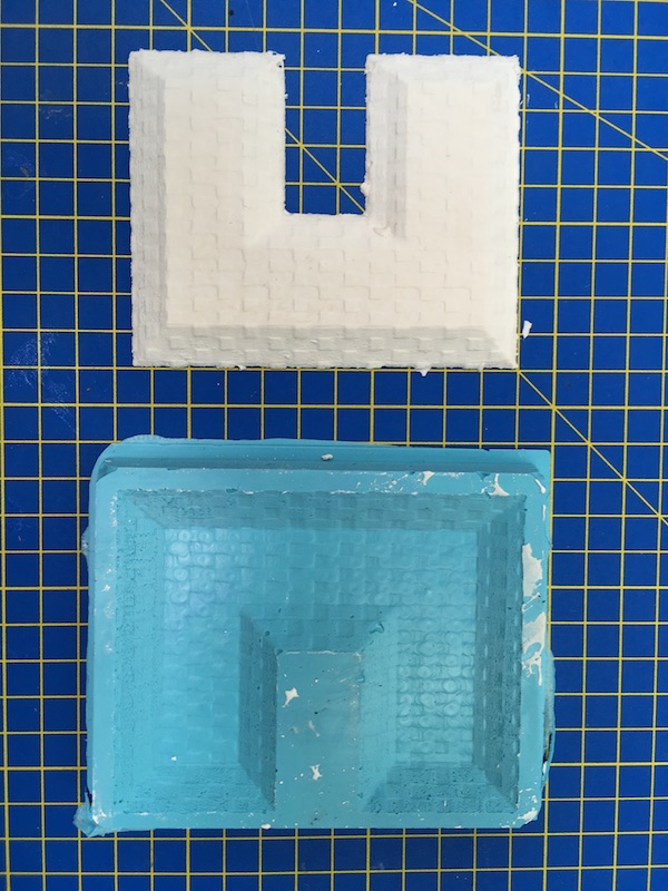
And here is this turned into the male mould to be machined out of wax on the CNC mill with a 15 degree draft on the walls.
![]()
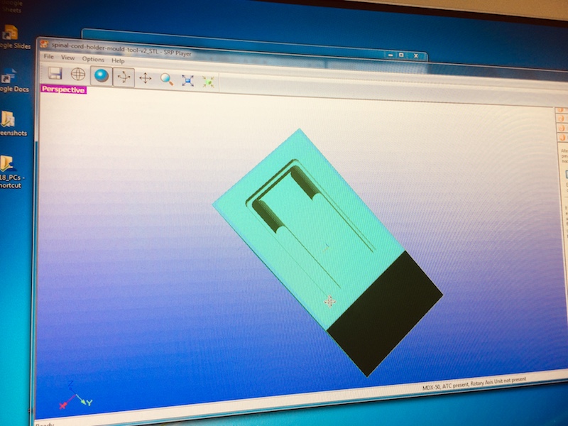
And here it is loaded into the
![]()
Here is the Rhinoceros file of the part to download
Here is the .stl file of the finished part to download
Here is the blender file of the part to download
Here is the .spj file (used on the Roland MX40 milling machine to mill the part) to download
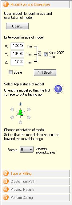
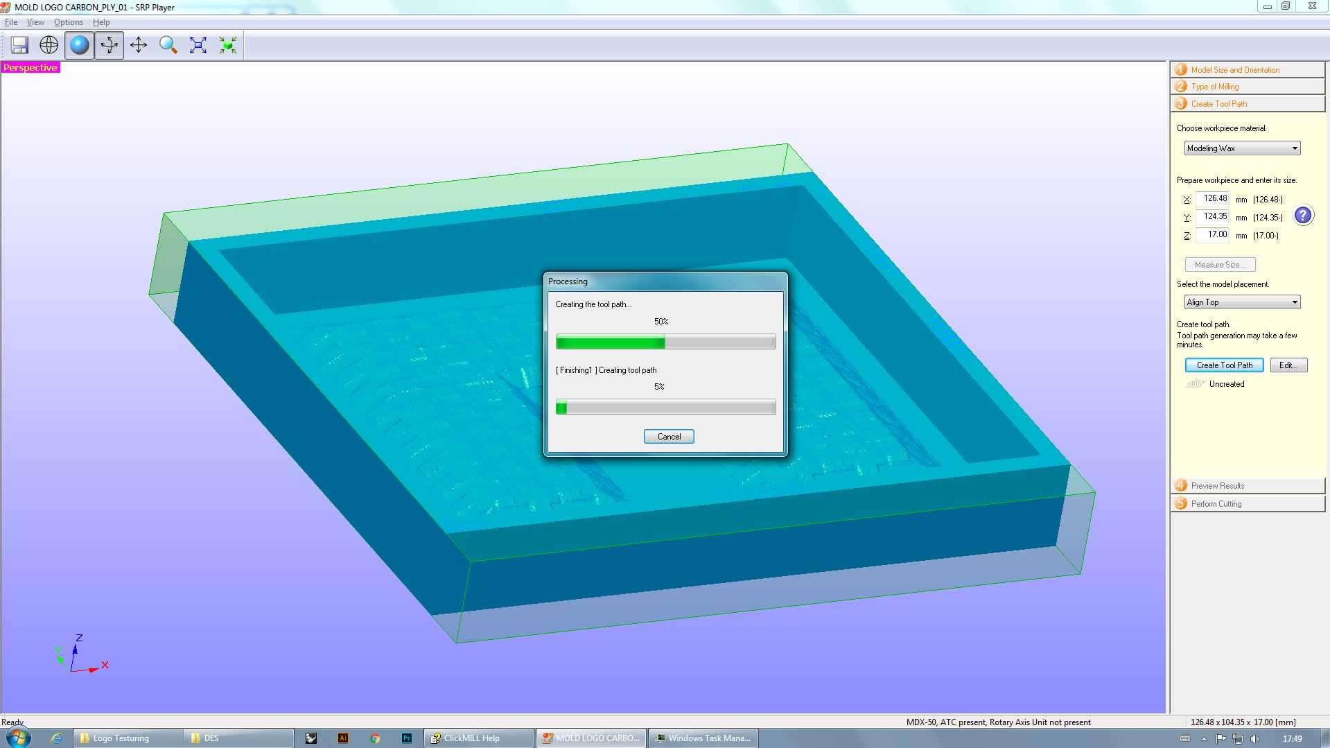
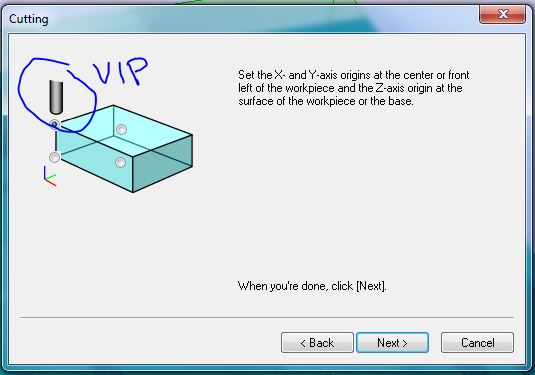
When loading the .stl file of the mould to be milled, the first step is to check the orientation of the tool to make sure it will fit with the stock material you are using, and that the orientation is correct! note the XYZ and how these correspond with your machine/part. Also note the dimensions of the model and the materials you're using (both should be measured prior to this step).
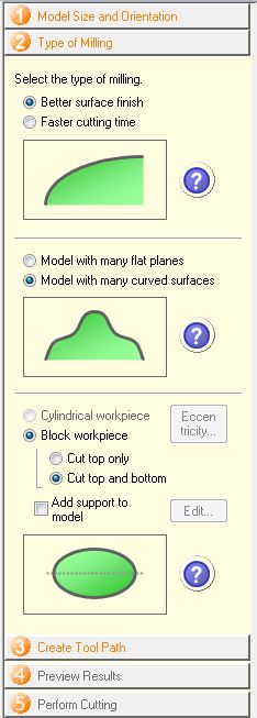
The next step is to define the type of milling used. Because I was dealing with so many very small surfaces, I opted for the slower but more accurate options. We are planning for two milling processes: Roughing 1, and Finishing 2...after these are defined I need to delete the other processes (e.g. Roughing 2).
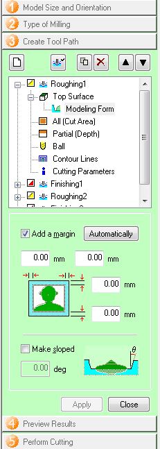
I didn't include any margin around the CAD model. This can be useful if you're unsure of the stability of the wall sizes in the CAD. Then click apply.
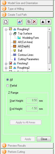
Then for Cut Area and Depth, choose ALL and click apply.
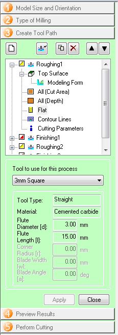
Then for Flat/Ball, choose the tool, in our case it was a 3 mm flat end mill and click apply.
We then create the toolpath and check how this looks, making sure it starts at the top surface
We then edit the Magazine and make sure that the correct cutting tools are in the correct place on the CNC milling machine. In our case here, the 3mm flat cutter was in tool 3 in our machine. We also want to delete any unwanted/unused tools from the magazine list. In this case we right clicked on the tool and reset it so it disappeared from the list.
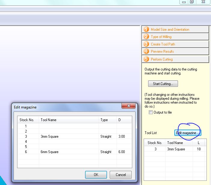
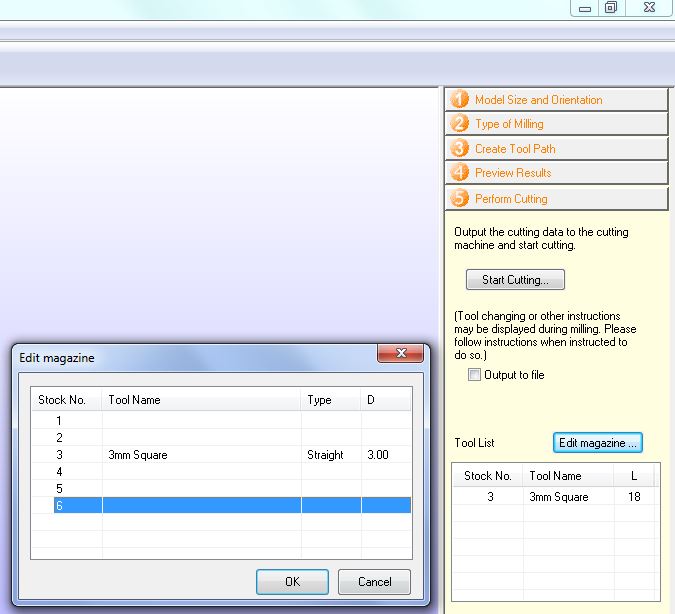
Then again we check the tool number - just to be safe.
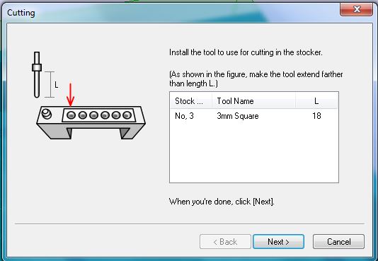
And the VERY important starting point for the cut, in most cases we'll use the front left corner of the tool, and this corresponds with XYZ0 as I've defined this on the machine....if not do it now!
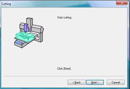
Then...we start cutting!
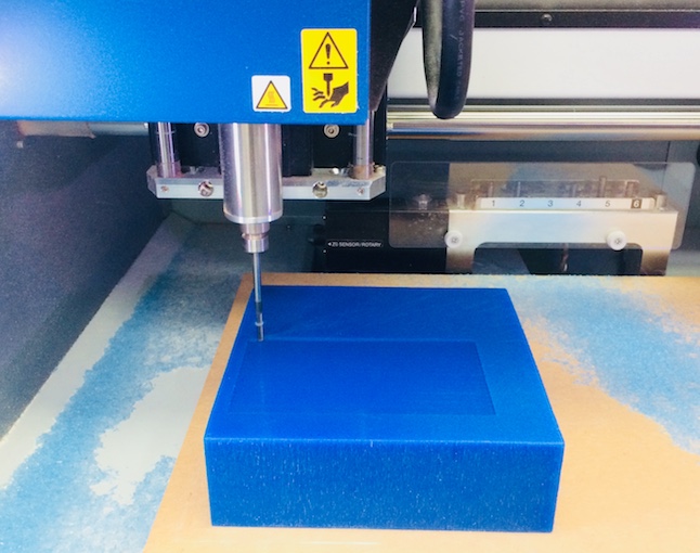
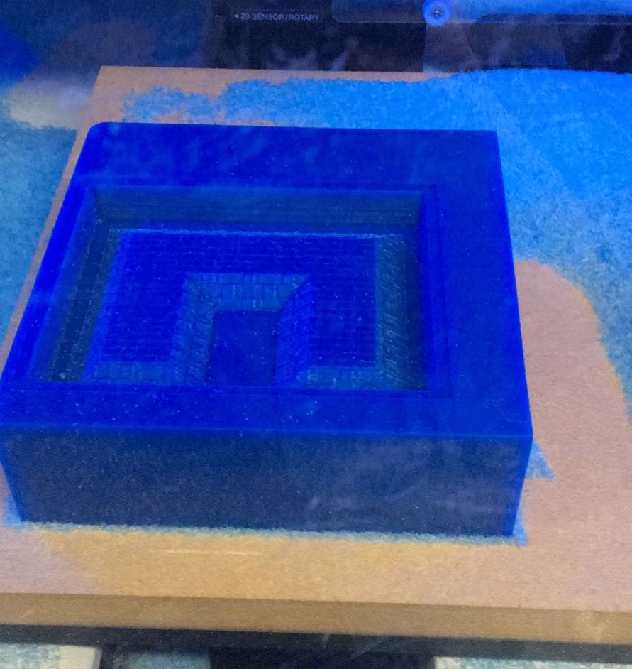
And it turned out a treat!! Now tomorrow we'll cast this baby and see how the detail comes out....the group are very excited to see it!
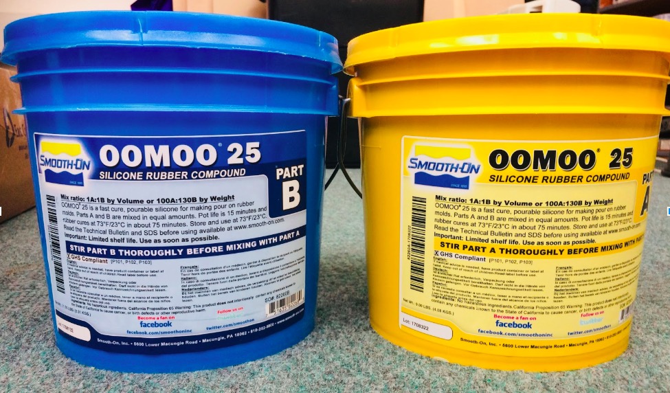
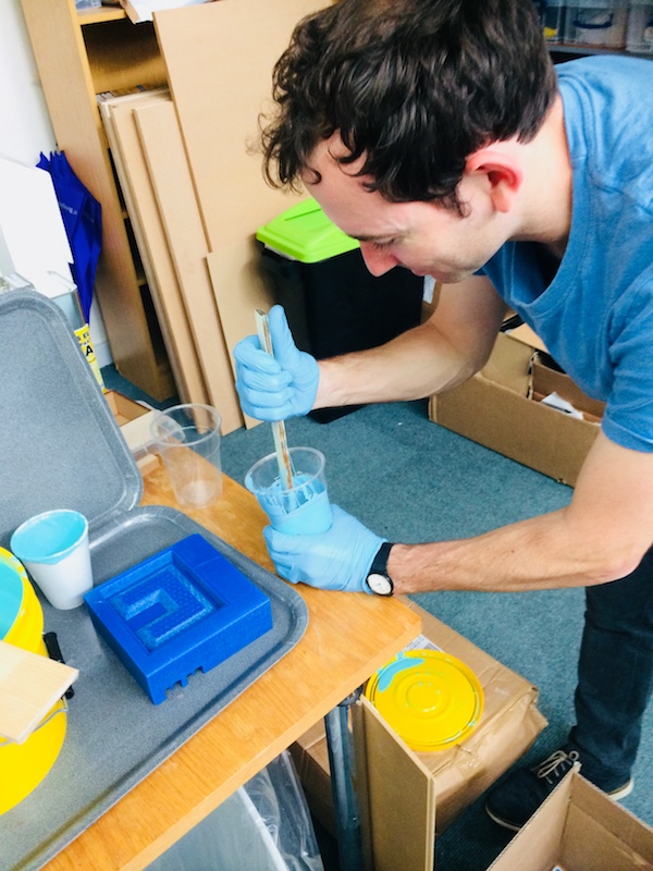
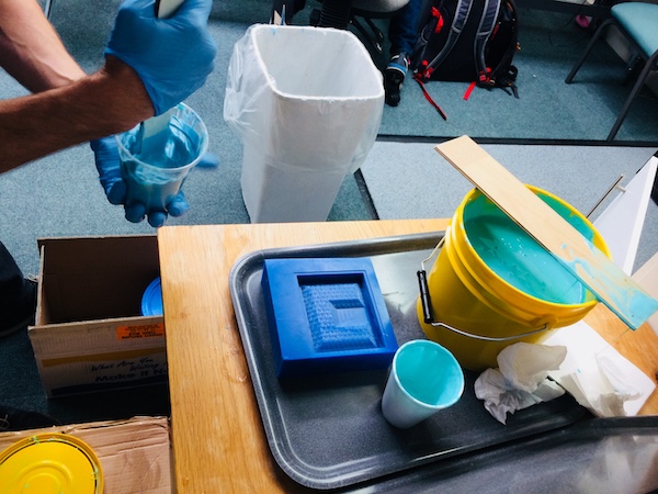
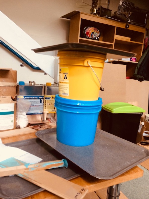
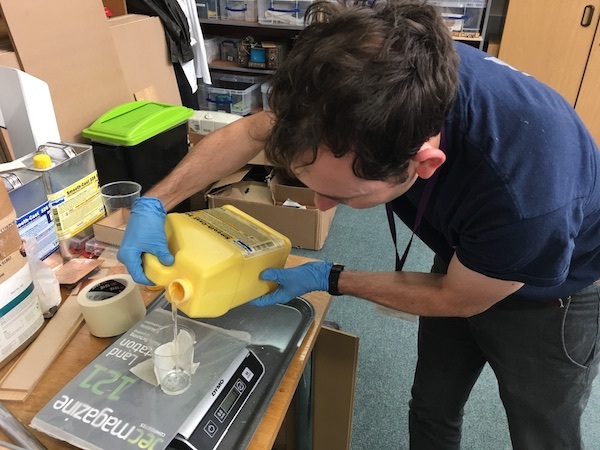
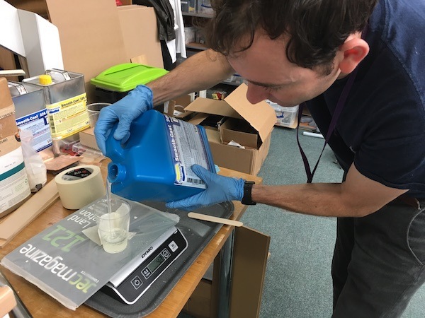
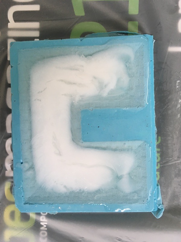
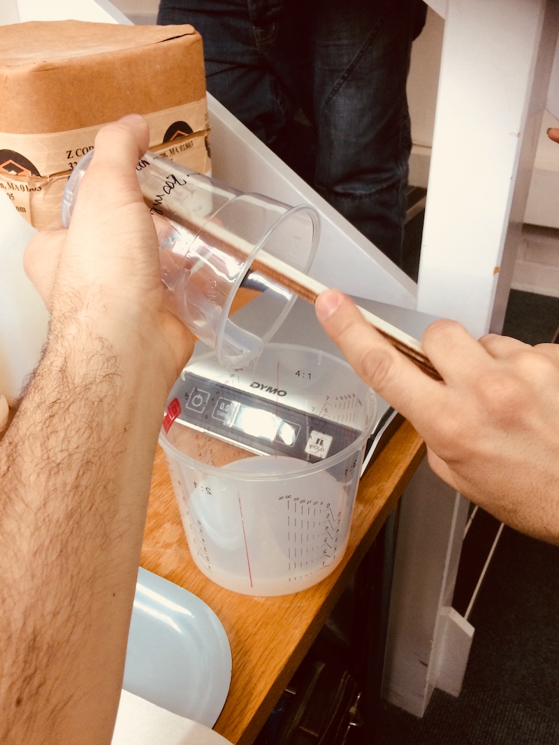
I used a two part silicone rubber compound called Oomoo25, some of the other guys had used it and it was a very nice silicone. It requires a 1:1 by volume ratio between part 1 and part 2.
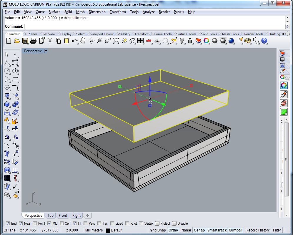
I used the mould tool model I created in Rhinoceros to measure the approximate volume needed. It turned out to be 160 mL, minus the original volume of the part itself of 40 mL so 120 mL. I rounded this up to 200mL, just in case there is some shrinkage or spillage, but also because we wanted to use a bit of leftover material to make a squeegee to clean the Roland CNC milling machine.
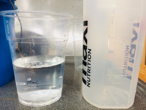
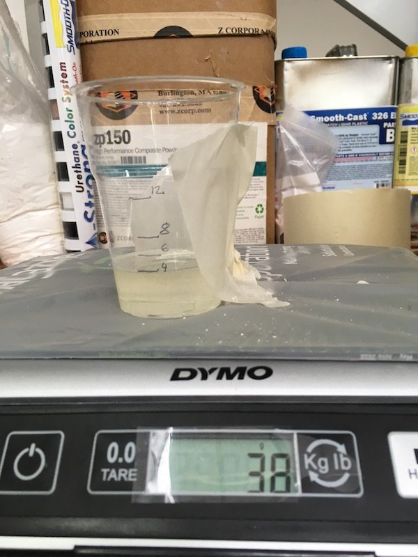
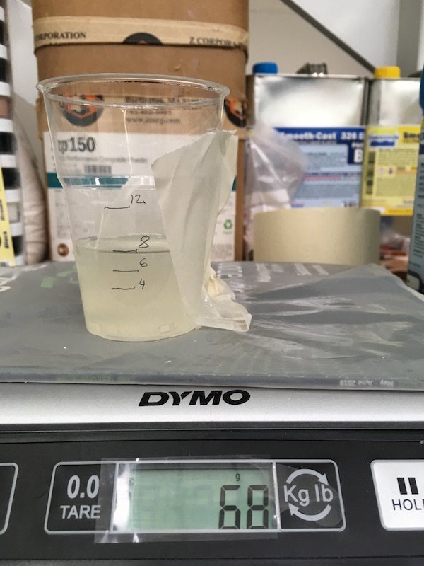
I measured out 100 mL and 200 mL on a cup so that I could simply pour in the correct amounts, one on top of the other then mix them together. I've used this technique to cast plaster before, and as long as you're careful it's a nice easy way to do it.
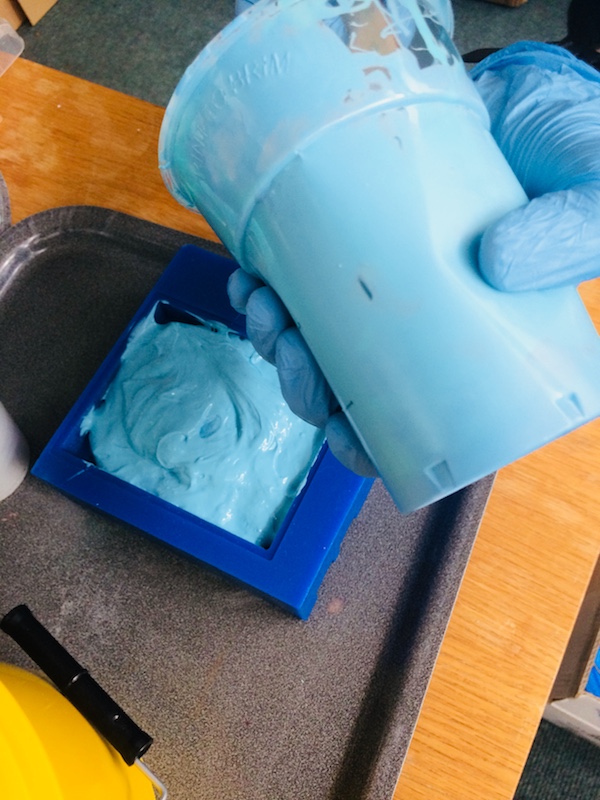
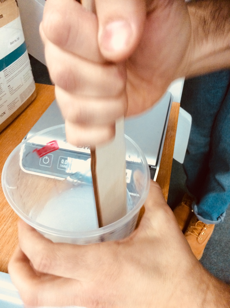
Then once both parts were poured together, the mixing began. Having not used this material before I was not sure of the consistency, and it was only when some of the others in the lab pointed out that it seemed more viscous than when they used it (about 2 months ago now), that I realise the shelf life of the silicone might have run out...especially since it had been open for so long. Worth a try anyway, so I kept going to see if we could salvage it.
Some more mixing, conscious to get all the sides and bottoms mixed in too, but also conscious not to take too long - there was a 15 minute timer on this, and I probably took half that in getting it ready to pour.
It was a VERY slow drip out of the cup, not a good start.
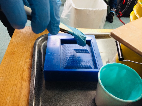
The texture by this stage was like chewing gum, really not ideal and I wasn't so confident, but still worth the try. I could (hopefully) easily peel the silicone off if there were too many pores or if it didn't coat the lining of the mould tool.
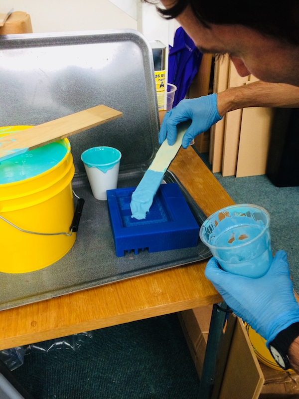
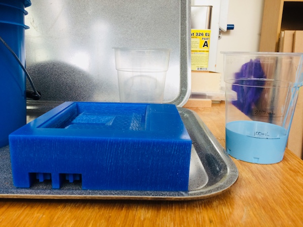
Scraping the last bits, then a desperate attempt to get the top flat...I put a restaurant tray on top with about 10 kg mass to try to press it down flat...after a few hours the sample offcuts were still slightly tacky (should have set in 75mins), so best to leave it overnight. Fingers crossed!
We had a bag of gypsum plaster in the lab so I thought I'd give that a go first. We've done quite a bit of casting with plaster and the detail that can be achieved is stunning, and it could be done quite quickly without much preparation so I started with that.
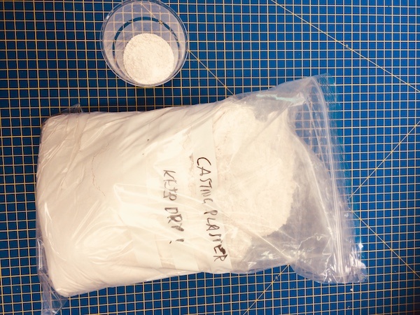
Here's a video of the preparation and pouring. I didn't bother to measure out the ratios with this one, I was simply adding water to the plaster and mixing as I went until I achieved a 'double cream' consistency. Then poured it in slowly to fill the entire mould cavity.
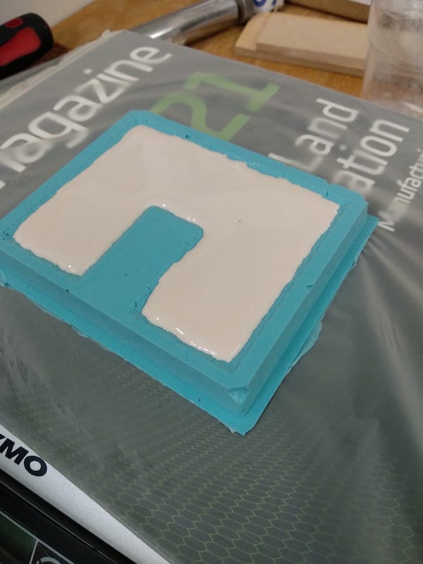
The result was quite good, although the acute angles on the sharp edges was very fragile.
I also 3D printed a PLA version to add to the collection. The 3DP version was printed vertically to best capture the surface detail.
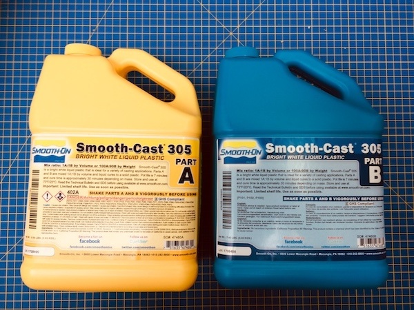
Next up was casting in a white two-part resin: smooth-cast 305 bright white liquid plastic.
I then poured in about double the amount needed using 4 table spoons (4 x 17mL) for both part A and B - I wanted some leftovers to also pour another mould we had lying around. I initially measured water and poured it into the cup with the spoon to create lines that I could use to guide my pouring with the resin.
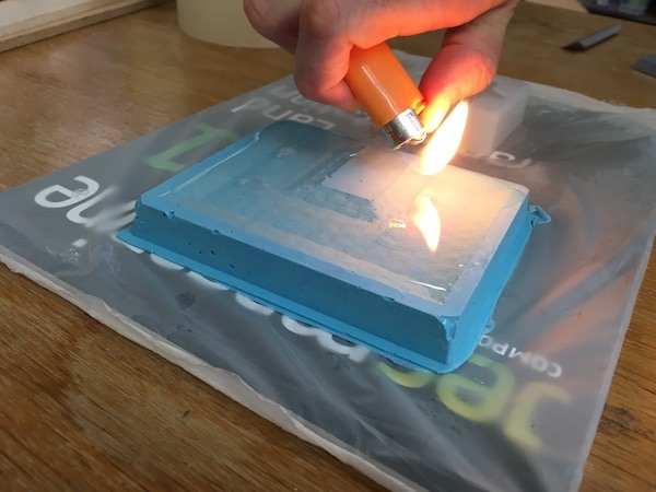
We then tapped the table to bring bubbles up from inside the mould (like concrete shakers), and removed the surface bubbles using a lighter...works a treat!
We then watched the exothermic reaction with wonder, noting that it starts and is most prevalent in the middle where the thermal mass of the resin is.
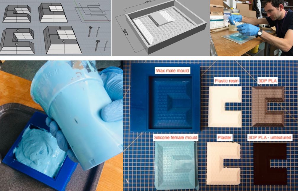
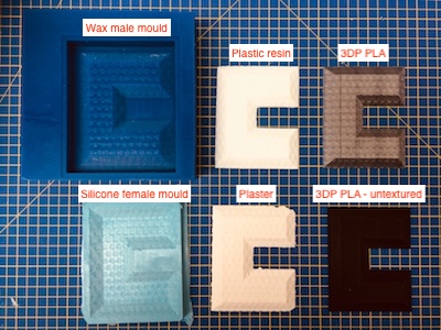
And here is the final result, with all the different logos made using cast gypsum plaster, 3D printing PLA, cast plastic resin, cast silicone female mould, CNC machined wax male mould.
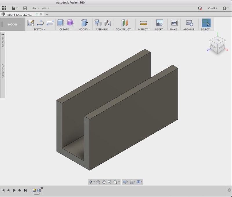
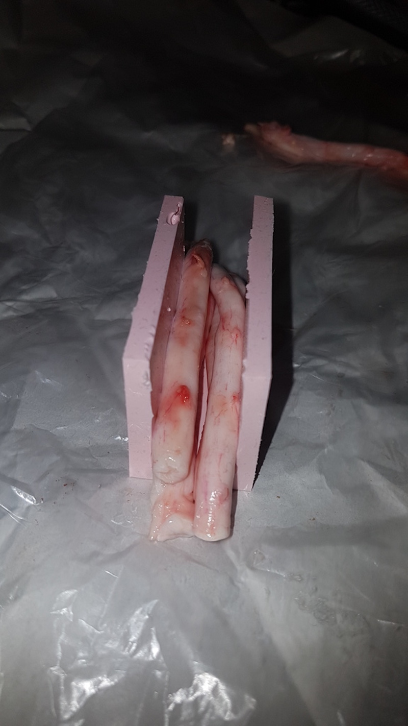
This week was also timed nicely with a request for a part that I received by a colleague in the clinical imaging centre (in fact I did this part first...just to have a quick go at the process). They wanted a small silicone part to hold some spinal cords while they were doing some testing using ultrasound and MRI scanners. While a simple part that could be made using an assembly mould (i.e. that doesn't actually require machining), it fit nicely with this week's project so I decided to make it by machining the mould. So this is the 'MRI standoff' part as they called it. I created it in Autodesk Fusion 360. It's 80 mm long x 40 mm high x 30 mm wide, with 5 mm wall thickness all round. This I used to create a drawing to send to my colleagues to check that it was suitable.
here is the original Rhinoceros file to download
here is the .stl file of the holder to download
I then needed to subtract the part from a solid block, with the part inverted so that the bottom was flush with the top of the block - as this is where it will be machined from, effectively leaving a bit void from the top with two slots running down the side into the block. It was a relatively straight forward process to then bring this into the SRP player software, although when allocating the tools to the various passes I realised that the tool wouldn't cut the sharp vertical edges in the cavity, so I went back, rounded these off by creating a fillet with the same radius of the tool (2mm).
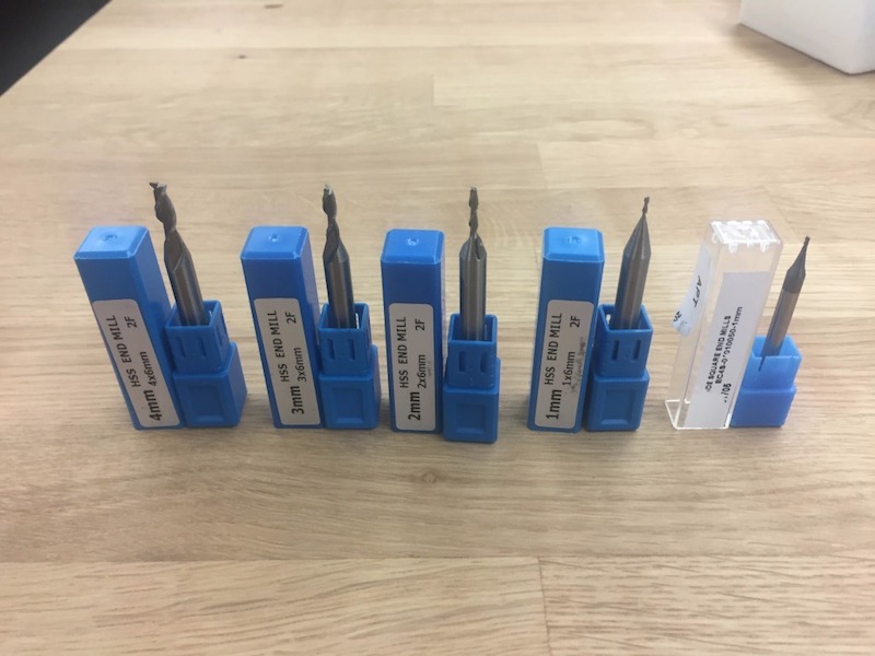
While for this exercise I only needed one cutting tool, we have cutting tools with diameters 1-4 mm. In the software, we need to specify the tool diameter, type (ball/flat), and flute length.
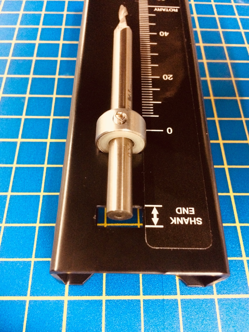
When setting up the machine, and in particular putting in a new cutting tool (my first time at this), it is important to set the position of the collet correctly using the tool shown here. We needed to change the cutting tool since previously we'd been milling PCBs, so it needed to be changed. Here's how to do it.
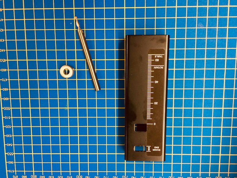
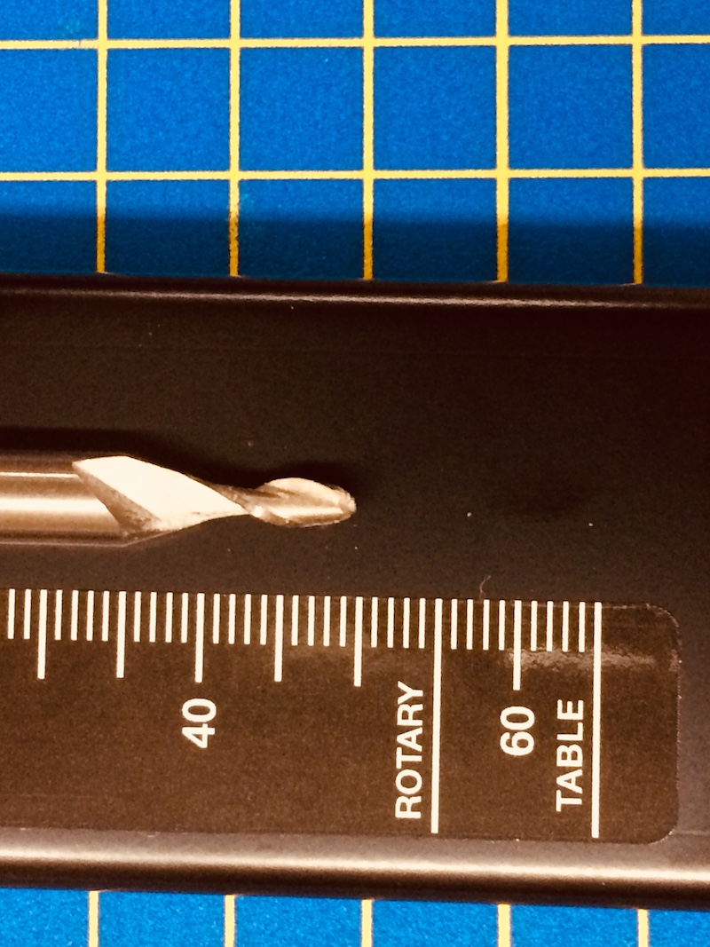
You place the bit into the tool making sure that the end shank position lies within the limits shown on the tool. You then also note the length from the bottom of the collet to the cutting end.
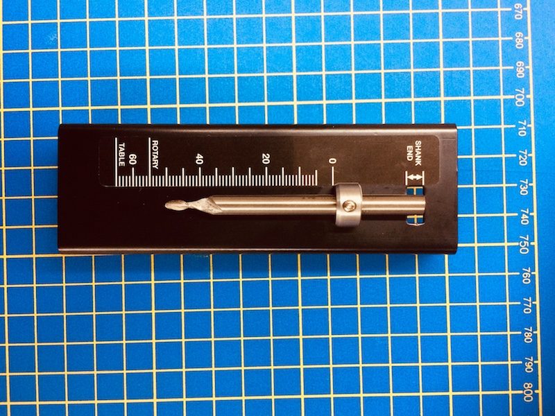
It is important to orient the collet the correct way up. The smooth white surface is on the top side as shown here.
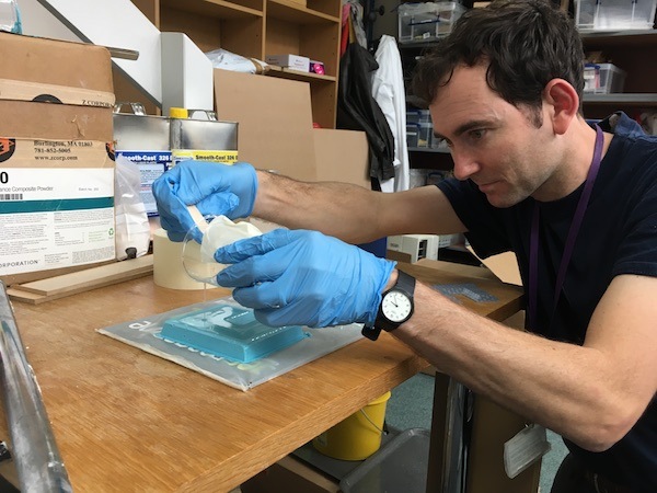
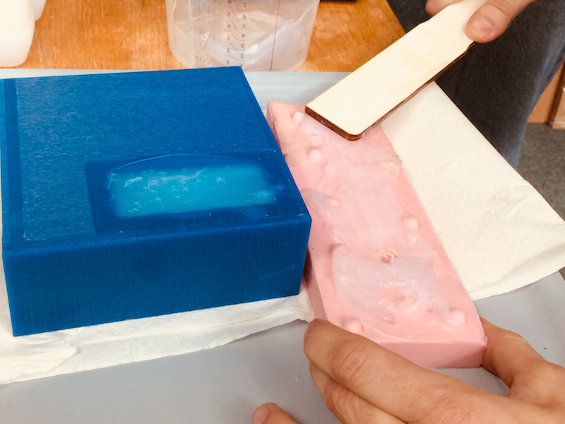
Machining the mould was quite straight forward using the same approaches that we've been using for milling our boards. Once the mould is machined, we measured out our 2-part silicone using the overall part volume needed, then halving this number to give us the volume needed for both parts (1:1 ratio required). I tried two different silicones, a very fast setting (2 minutes) clear silicone which is quite stiff, and a much longer setting (approx. 3 hours) pink silicone.
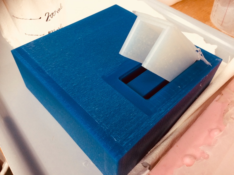
After mixing quickly but thoroughly, I poured the silicone into the mould making sure to coat all the internal surfaces of the mould so that there were no bubbles on the wall itself. This is an important step. We also made sure that the top surface was flush with the top surface of the mould to make the base of the part flat. Note: in the design of the mould, we created a small offset and a small well for the part so that we could over fill our part, but without having to go over the top of the mould itself. We could then cut off the bottom of the part to make it the right size.
We had a little left over (mistake with original volume calcluation??), so we put it into a spanner mould we had lying around just to try to make use of it.
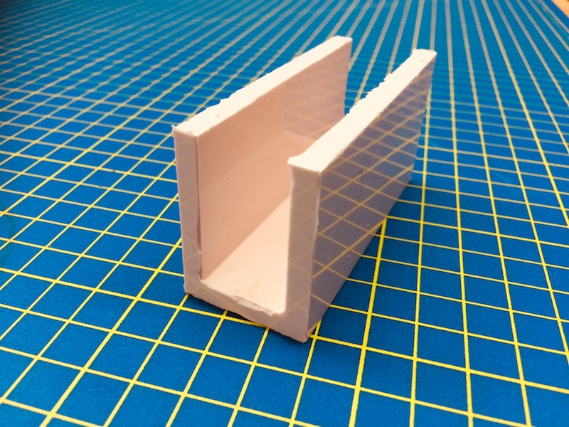
Removing the silicone parts is always a very satisfying task, like peeling off an old scab or annoying sticker all in one go. When it pops, you know it's on it's way, but you do need to be fairly careful not to rip the silicone by bending it too far. Here's the clear silicone part, which was nice and stiff, but had far too many bubbles in it. It simply set too quickly, and we didn't degas it in the vacuum casting chamber.
We then did the same in the pink silicone, but we had much longer to mix it (tens of minutes), being careful not to include air bubbles, and we degassed it also to make sure there was nothing inside. The pink model was much smoother, with a (mostly) great surface finish. As a material, it is much more flexible too, and not nearly as strong. The clear silicone is much tougher, more hard wearing.
![]()
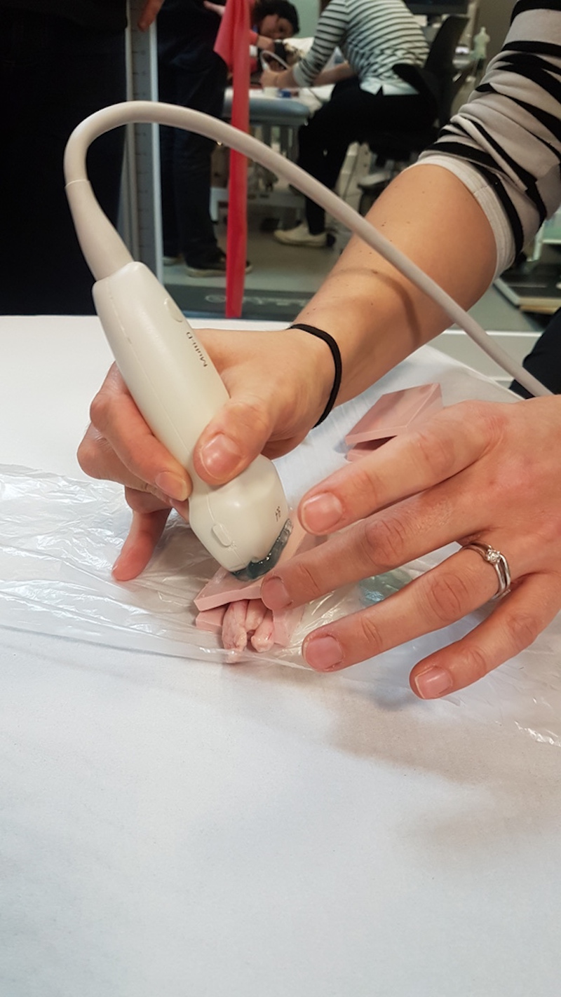
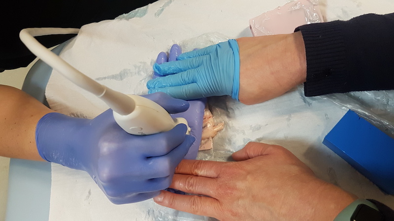
I then delivered the parts to my colleagues at the clinical imaging centre and they were used the next day in the MRI scanner and with the ultrasound too. Overall the pink one was useful in the MRI (as it didn't have any bubbles and was a good holder) but not with the ultrasound (as the contact wasn't great and it wasn't jelly enough). One interesting finding was that the MRI showed the porosity of the clear standoff beautifully.
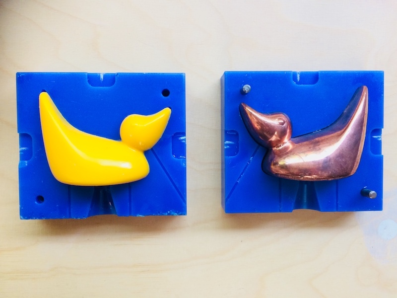
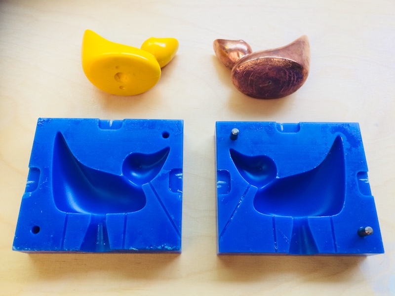
We also came back and played around with the moulds that we created for the carbon fibre duck, instead this time using a yellow expanding polyurethane and then using a 3d printed duck that we electroplated in copper!