Week 4 - Computer-controlled cutting
Assignment tasks for this week
1.0 Group assignment: characterize your lasercutter, making test part(s) that vary cutting settings and dimensions.
2.0 Individual assignment: cut something on the vinylcutter design, lasercut, and document a parametric press-fit construction kit, accounting for the lasercutter kerf, which can be assembled in multiple ways.
Assignment summary
what I achieved/learned this week:
- learned to create parts, assemblies and drawings in Fusion 360
- created a set of parametrically driven jigsaw pieces and assembled them in Fusion 360
- laser cut a set of these jigsaws using acryllic
- carried out a simple finite element study to look at the stresses induced during press fit of the acryllic jigsaw pieces
- designed and made a syringe holding rack with parts and assemblies in Solidworks
- created some detailed instructions for using the laser cutter
- created a vector drawing from an image and vinyl cut a sticker for my laptop
Group assignment
Here is a link to our lab's page which includes links to all our group assignments.
Individual assignment: part 1 laser cutting
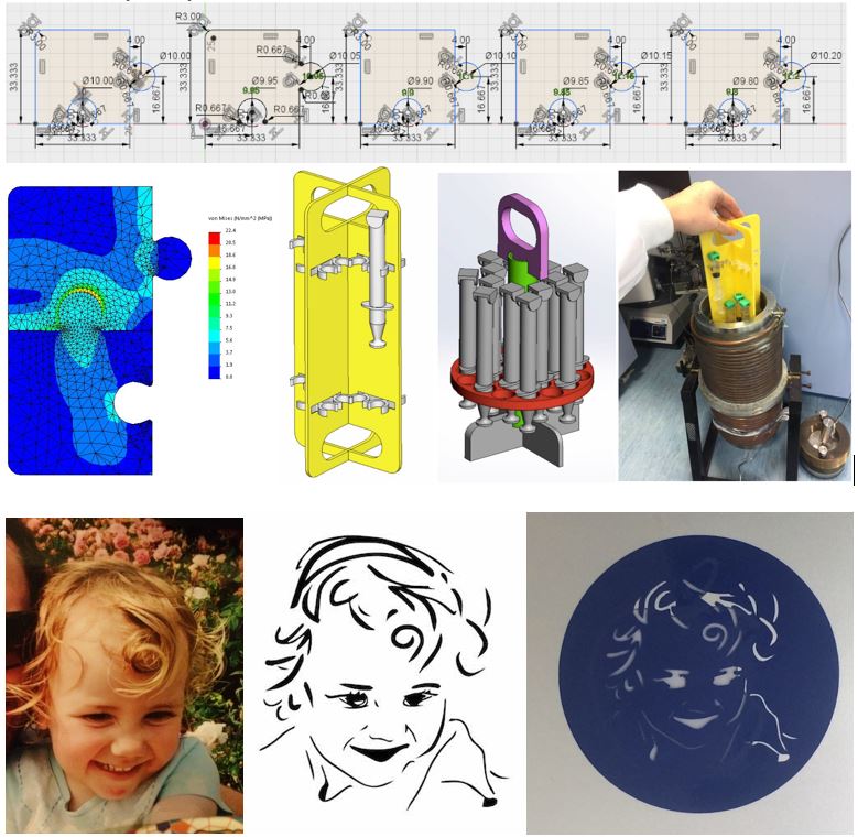
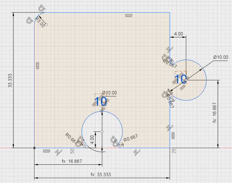
I thought it might be interesting to create a press-fit jigsaw puzzle, which was parametrically designed to demonstrate various types of press fit (heavy press, medium press, light press). So for extra practice using Fusion 360, I created a single piece with the reference 10mm hole/lug diameter, then other pieces which were parametrically linked to it, decreasing by intervals of 0.05 mm for each subsequent hole and increasing by 0.05 mm for each lug. That way, various combinations of fit could be achieved by assembling the various pieces together. Here's the original piece.
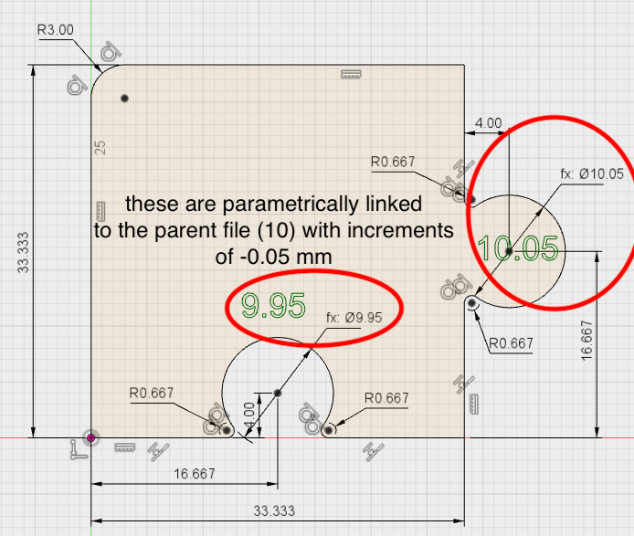
and here's the first 'child' piece, with the increment of 0.05 which has been parametrically linked to the parent so on each child one lug will increase by 0.05 mm, and the other will decrease by 0.05 from the previous part.
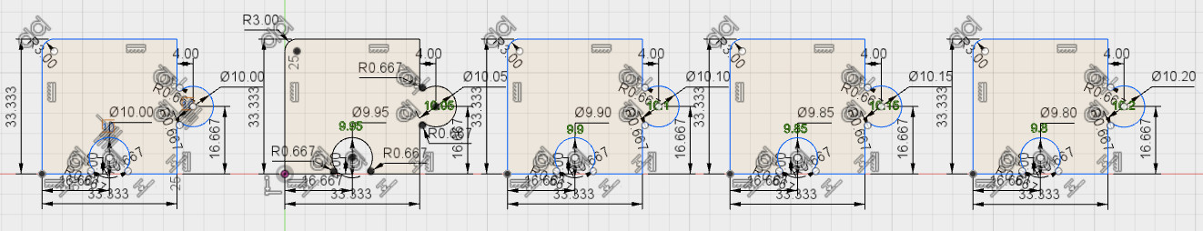
and here is the sequence of pieces.
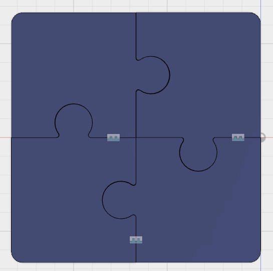
and here is the assembly of 4 pieces, if you look carefully you can see the interference between the parts.
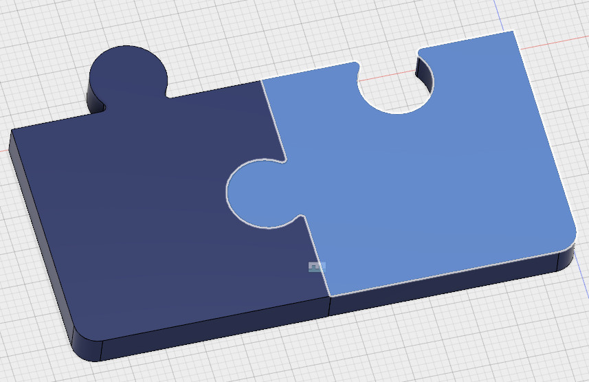
and here are two parts assembled and shown in 3D.
here are the solidworks part/assembly files for the jigsaw download
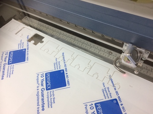
and here are the pieces being cut on the laser.
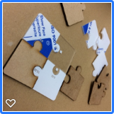
and here is the final result assembled. It didn't quite work out as planned, the KERF for the acryllic was larger than the early MDF models so the range of press fit wasn't quite as pronounced as I'd have liked. I should extend this range to include larger offsets to get a heavier press fit.
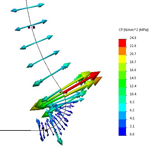
for a bit of a jolly, I also thought it would be interesting to do a 'shrink fit' FEA model using Solidworks Simulation. In the shrink fit contact condition it allows us to analyse the stress field and contact pressures on the parts. From the stress field we get a sense of whether or not the part will yield (typically on the hole), but if we also know what the co-efficient of friction is for this material when rubbed against itself, we can also work out what the actual force needed to press the two parts together would be. Solidworks Simulation can also generate parametric FE models, I might try to use this tool to look at the sensitivity of the results to the diameters, and other parameters too (e.g. fillet radius joining the lug to the body of the piece, offset distance for the centre of the lug) ultimately, I'd like to produce a spreadsheet or web-based application that has the following details:
- input: kerf width, k (mm), or even material type/thickness (mm)
- input: press fit type (light, med, heavy), a
- input: nominal hole diameter/slot width, b (mm)
- lookup: table for a,b; generate h0 (hole), shaft (s0)
- output: hole/slot size, h1=h0-k (mm)
- output: shaft/tab size, s1=s0+k (mm)
- bonus output: example jigsaw file generated automatically, based on above (if I have time!)

Individual assignment: part 2 laser cutting
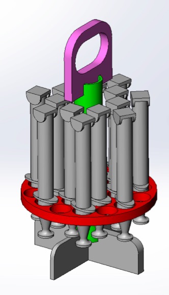
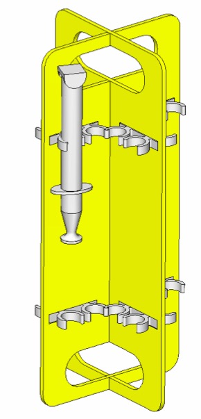
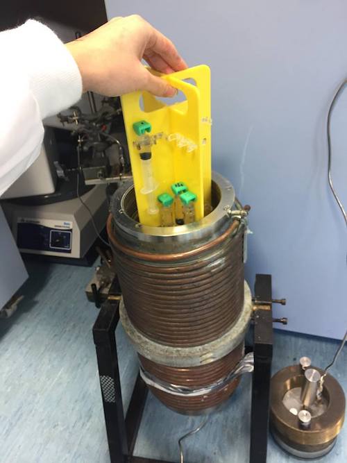
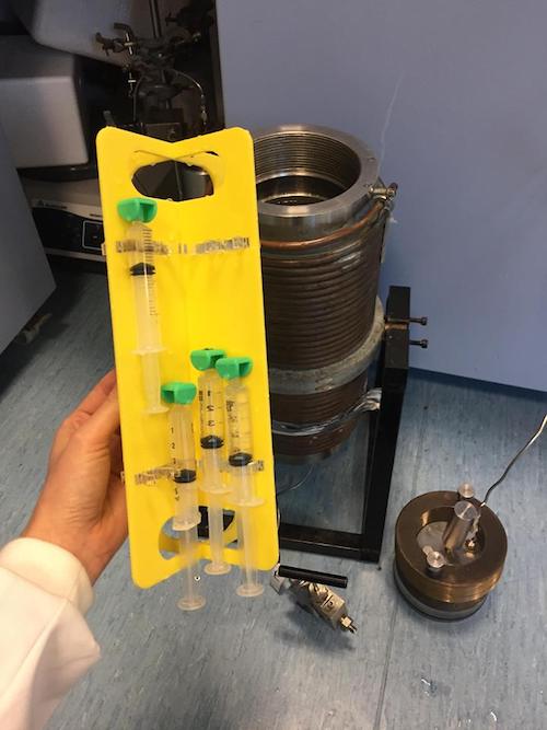
I have also been working on producing a press fit syringe holder for a pressure vessel we have on loan from a colleague in Edinburgh. I drew these on Solidworks as I was quite short on time and I know SW well. I designed it so that I could parametrically generate the clip holders to test various diameters, degrees of taper and wall thicknesses so that I could test which holder shape/size held the syringes without breaking, but with sufficient friction for it to hold the syringe in transit. I did an original design, but found it to be not so stable and not ideal structurally, so I redesigned it in the following few days. Here is the original design (left) and the new design (right).
here are the Solidworks part/assembly files for the rack to download
Instructions for using EPILOG LASER (HELIX) laser cutting machine
The laser cutter is an amazing machine, cutting out 2D geometry from (mostly) flat materials like card, ply wood, MDF, fabrics, acryllic by firing a fine laser beam to burn, melt or vaporise the material. Here are the instructions for using our machine.
Turn on machine. Note we work down from button
9,8,7,etc...which takes us through the process step by step.
9. Press POINTER - Point on/off
8. Press X-Y OFF - press GO to confirm (this will turn off the
motors which move the laser in X-Y) 7. Press SET HOME - Then
physically move gantry to starting position (0,0) - press GO
to confirm 6. Press FOCUS, then put on magnetic height tool
and adjust the bed height using up and down until it is just
touching.
SOFTWARE: Go to cutting software (e.g. Rhinoceros or
Illustrator), and import the .dxf file. Make sure your lines
are joined together, this will ensure that the laser works
sequentially around the drawing (rather than moving randomly
between lines).
In Rhinoceros, FILE > PRINT. Click on SET (in , to define
the bed size. Then place it over the top of your drawing. Note
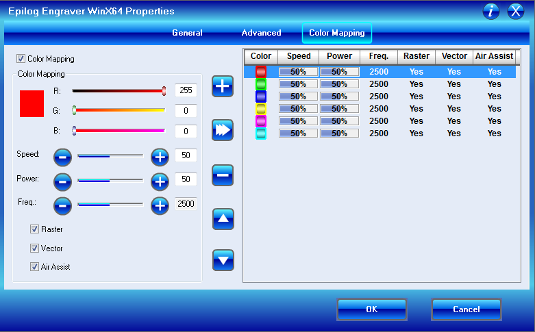
that in Rhinoceros you can adjust the colour/line thickness of
various LAYERS, so if you want to change lines from vector
(cut) to raster (engrave), adjusting the colours/line
thicknesses in lasers is the best way to do this.
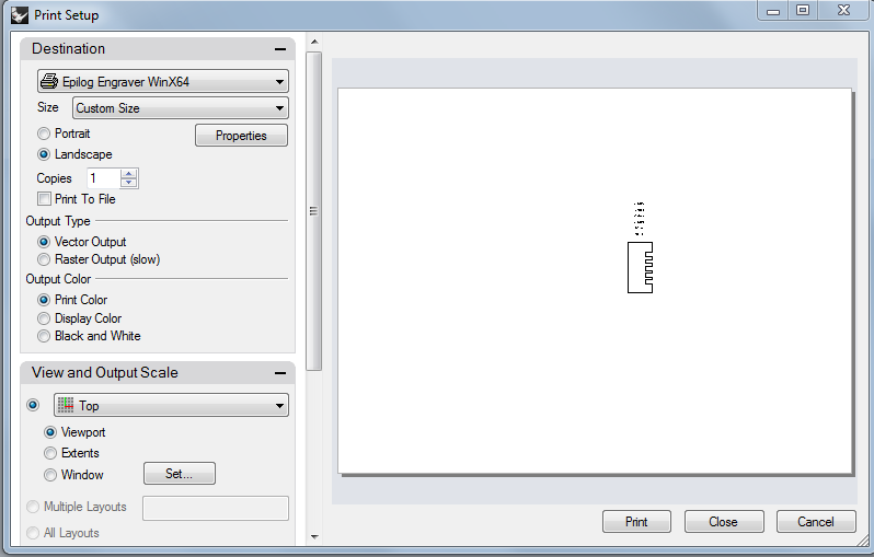
In Photoshop, FILE > PRINT. Click on PREFERENCES Click on
PROPERTIES. These are GENERIC properties for this laser
cutter, regardless of software. Note: PIECE SIZE is 609 mm x
457 mm, and usually you want to start the cut from TOP LEFT
(click on little icon).
Note: sometimes you need to go into the SETUP twice for the
piece size to register.
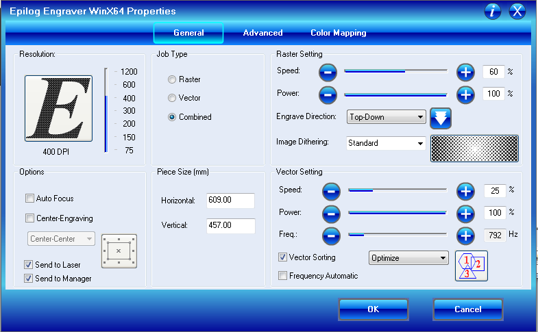
For 2mm MDF: Raster Settings: 50% speed and 100% power is good
for MDF. Vector settings: Speed 35%, power 100%, frequency 800
Hz. Works fine!
For 3.2mm MDF: Raster Settings: 50% speed and 100% power is
good for MDF. Vector settings: Speed 35%, power 100%,
frequency 800 Hz. .. THESE DID NOT CUT THOUGH PROPERLY! Let’s
start again…
For 3.2mm MDF: Raster Settings: 50% speed and 100% power is
good for MDF. Vector settings: Speed 20%, power 100%,
frequency 500 Hz. ..Works fine!
For 2.10mm ACRYLLIC: Raster Settings: 50% speed and 100% power
Vector settings: Speed 40%, power 100%, frequency 5000 Hz.
..DIDN’T QUITE CUT...changed speed to 30%, only just cut, same
for 25%, then speed 20% CUT NICELY!
BACK TO THE MACHINE... Then, before actually cutting, we MUST
turn on BOTH the BOFA extraction system (under the PC
monitor), AND the COMPRESSOR (which is on the shelf against
the wall). Then press GO and the cutting will start.
After the cut has finished, leave the extraction on for about
seconds to clear the smoke.
Notes on other buttons on the machine (not needed to actually
cut):
5. JOB button, allows us to select a particular job that has
been sent to the machine. 4. POWER button, allows us to change
the power of the machine manually (not using the software). 3.
SPEED button, as above, but with speed.
Instructions for laser cutting from Illustrator
Individual assignment: part 3 vinyl cutting
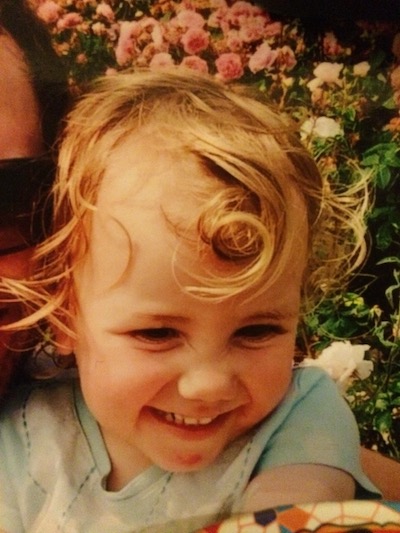
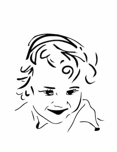
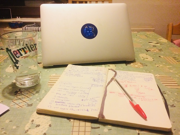
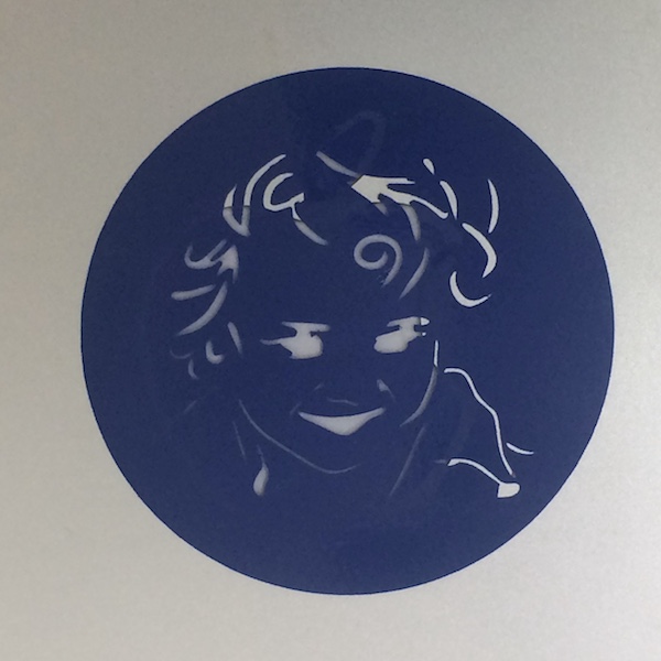
The vinyl cutter is a great machine, cutting 2D geometries out of thin materials using a blade to cut the surface (like a scalpel) by moving both the blade and the workpiece. It's great for cutting vinyl, decal paper, copper traces, and other laminating materials. I wanted to create a fun sticker for my laptop, so I've chosen to immortalise my daughter in a simple graphic created on a tablet using Autodesk Sketchbook. It's a great tool, that I use with her to create drawings that she can colour in. I simply brought in a picture of her on a layer, then made that layer a slightly translucent, then created a new layer over the top of that and drew with lines on that layer. Once I was happy with the drawing, I hid the layer below with the image on it and that left me with the file (.jpg) ready to export to Illustrator. I could then cut directly from Illustrator. Here's the original pic and the graphic I created.
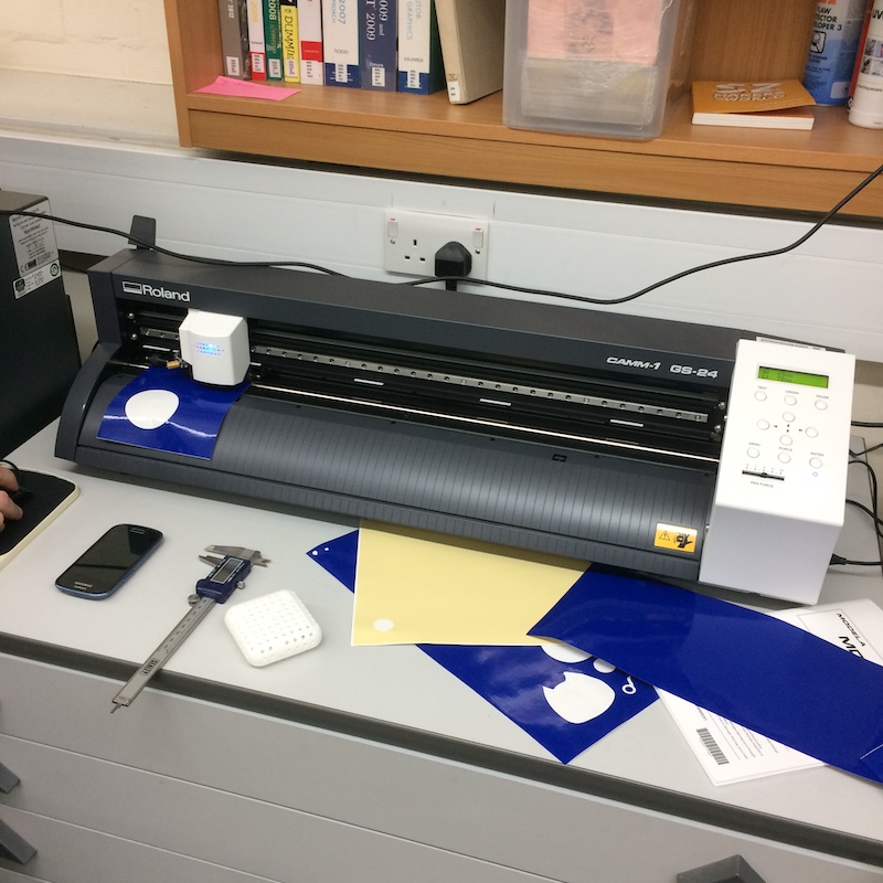
Here's the Roland GS-24 machine ready to go!
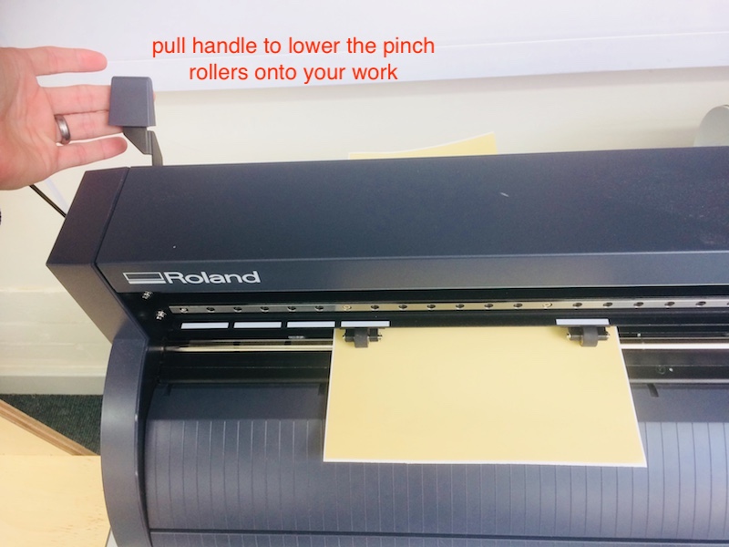
Setting up the machine. Firstly, turn the machine on, then push the handle at the back of the machine to raise the pinch rollers. Put your material in and make sure that the pinch rollers are within the white labels otherwise they won't be secure!! here's an example of how to do this.
![]()
Then pull the handle to lower the pinch rollers onto the material.
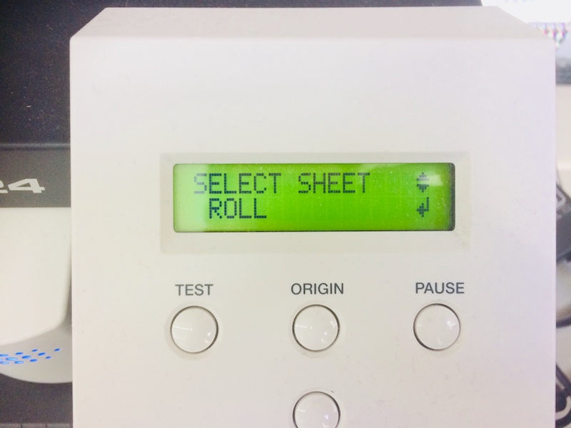
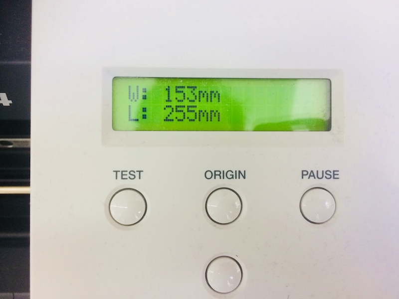
It will then move the cutter over your piece and measure the size of it.
I've used illustrator here, and we can cut directly from this package (only on the PC attached to the cutter), using File > Print. You'll see the Roland GS-24 in the printer list. Then click on Setup.
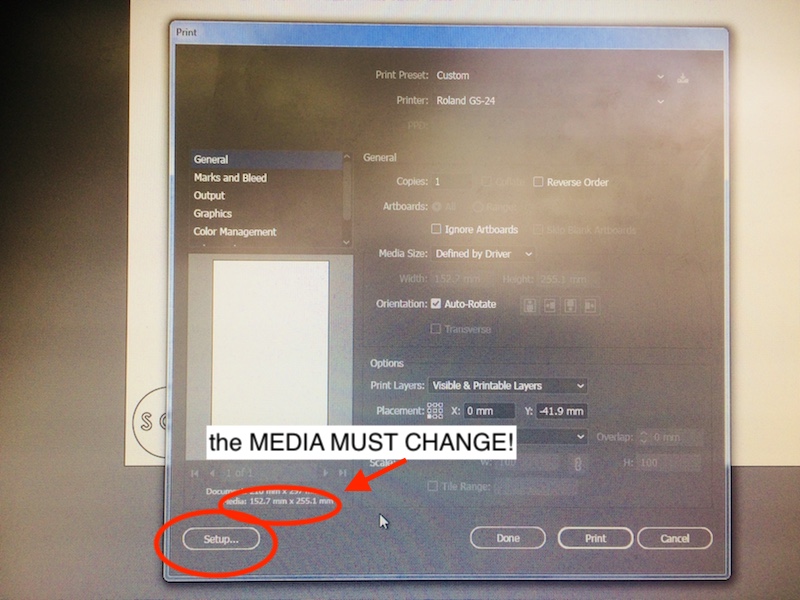
The idea with the setup is to make sure that the media reflects the size of your piece/roll/sheet. Do to this you often have to use the GET FROM MACHINE tool a couple of times from the preferences.
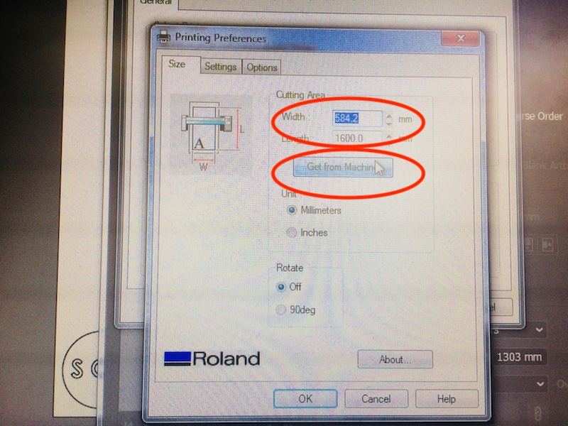
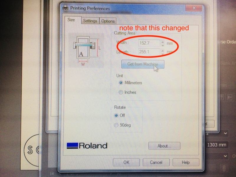
Once the media size is correct, you can click OK, then click Print and your shape will start cutting! Make sure you keep your fingers away!
Here it is cut out
here is the Illustrator file to download