Computer Controlled Cutting
Softwares Used
Vinyl Cutting
When I started working on the vinyl cutting portion of this weeks assignment I was unsure of what I wanted to make. Many of the examples I had seen were laptop stickers, so I opted to do this so I could focus more on the group project and my plans for the laser cutting assignment.
I began by selecting a design I wanted to cut. My background is as a musician and I use my laptop to produce music, so something music themed seemed appropriate, however I wanted a design that was more complex than a simple note or instrument design. I opted for 'the flower of life', a piece of sacred geometry consisting of several overlapping circles. It is said that the sizes of the spaces left between each circle are equal to the spaces between the tones and semi-tones found in Western music.
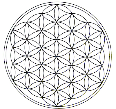
The Flower of Life.
I dropped the pattern into illustrator and used the 'trace' tool to turn the raster image into a vector image that would be possible to cut. After doing this I transferred the vector image to Rhino to make editting easier. When I was satisfied that all the curves were properly joined I made a small test cut. I then transferred the vector image into Easy Cut Studio, to finalise the size of the cut and the parameters of the machine.
Positioning the vector image in Easy Cut Studio and setting the parameters of the cut.
These were the settings that worked best for my material on the vinyl cutter.
I placed the vinyl sheet into the cutter, taking measurements made by the machine to properly dimension the scrap material for the cut, rather than measuring the shape by hand.
Once the cut was finished I taped the top of the surface in order to carefully remove it.
Failure!
The lines that form the pattern were too thin to hold together properly and the whole thing broke apart at the first cut. In order to fix this issue I ported the file back to Rhino to make some adjustments and opted to print a much larger sticker for my finished cut. As you can see, in Rhino i did not have to redraw the shape, I used the offset tool to increase the width of the lines so that the sticker would be more stable.
Offsetting the image in Rhino.
Once this was done the lines were much wider, meaning that they wouldn't pull apart after they were cut. I then prepared to make a second cut in the same way that I had done the first, still making the measurements of the vinyl piece using the sensors on the machine for increased accuracy and speed.
The sticker after cutting.
As you can see, the second cut was much more successful as it was actually possible to remove the remaining segments from between the lines. After I had got all of them out, just by peeling them away with a sharp edge, the sticker looked like this.
The finished product!
As you can see, the second cut was far larger than the second, in order to imrpove the strength of the sticker. In order to remove it from the tape i just pressed the sticky back of it to the laptop, smoothed it with a credit card and them slowly peeled the masking tape from the front of it. It has come out with a very clean cut and a high level of precision.
Laser Cutting
The main task for this week was to create a laser cut press-fit construction kit, from which it was possible to build a number of different structures. This immediately made me think of PlayPlax a toy that I had when I was very young, that was handed down to me by my mum. The toy was originally invented in 1966, but has since been discontinued, and I no longer have my set from when I was a child. For this reason I decided to make FabPlax, a take on PlayPLax that borrows from the original designs, but adds curvature, as well as a new triangle shape, removing the cyclindrical one that I always felt didn't really fit with the rest of the set. The pieces will be made from mdf so that they are renewable, rather than the original perspex material, I thought about using cardboard, however don't beleive it will be strong enough. Therefore, I will use cardboard for test cuts as it is far cheaper than the mdf that the product will eventually be made out of. I will also make and engrave a press-fit box for the different pieces.
My first step was to start designing the square piece in Fusion 360, I already knew the kerf of the laser from our group assignment, and I had pre-measured the mdf material. This meant that I could input them both as user parameters and make my designs parametric this way. This means that if somebody wanted to use a different laser or material to make the kit it would be easy for them as all they would need to do is alter the dimensions set in the user parameter.

Setting parameters in Fusion 360
After doing this I started to build my shapes. I started with the square as this is the piece that I would like to have the largest number of. I created a centre-point rectangle that was 60x60mm and began adding slits, defined perpendicularly to the centre of each side, of a 14.5mm length. This would allow the pieces to be inserted on either side at once without meeting on the middle of the joining piece. After making one slit, I defined the dimensions of the others by the dimensions of this first one. This way, if I need to modify them, I can change the dimensions of every one at once by midfying just one part of one sketch. After I got the dimensions correct, I filleted the corners of the shape by 2mm, this will guide the slits together better than a right angle would, it also makes the toy safer for potential younger users by removing sharp corners.
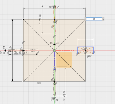
The sketch of the square piece, including dimensions, before extrusion.
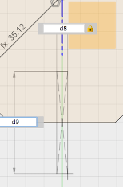
Defining parameters using lengths of other sketches(width = d8, length = d9).
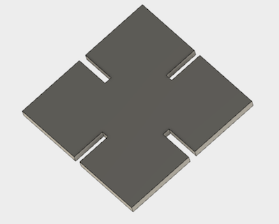
What the square looked like after extrusion to the depth of the mdf.
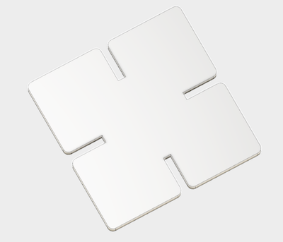
I filleted the sharp corners of the shape.
After making my square piece I moved onto the octagon.I formed it using the polygon tool, as a sketch in a seperate component. I went through the same process to define the boandaries of the octagon, the slits were made using the same definitions as on the square to ensure that they remained the same length and were easily modifiable across each component.
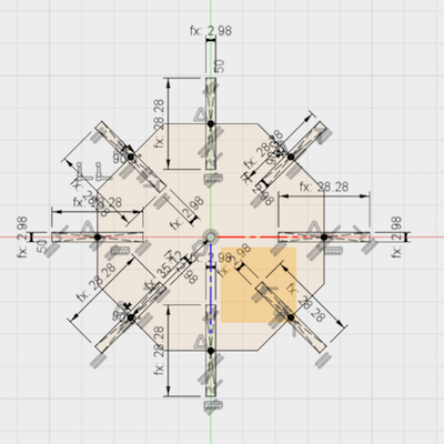
The sketch for my octagonal piece.
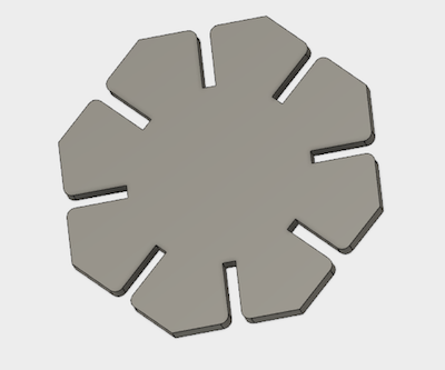
Extruded octagonal piece.
I then moved on to a triangular piece, this was not present in the original set, however i wanted to add it in as triangles can form strong bases for structures. I soon learned that it may not have been included in the original set as the angle of the sides of a triangle would cause pieces to overlap if the slits were left the same length. Because of this, the slits in the triangle are defined differently and may require more editing to get right. I set them to 15mm lengths for now and if this roves too short I will edit accordingly.
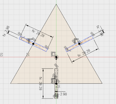
After making this sketch I realised the dimensions of the slits would have to be altered. As you can see, if a piece were added to either side it would not be able to push fulls into the shape.
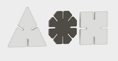
All the shapes intended as building blocks, the traingl with it's altered slit lengths.
After finishing this, the next step was to design the press-fit box which the shapes would be kept in. It will be constructed from the same mdf as the geometric pieces, and held together by tabs that slot together. It will have a lid constructed form two pieces of mdf stuck together so that it has an external extrusion, created by offsetting the original square shape of the lid by 'depth', that presses against the inside of the walls. The 3D designs from it can be seen below. They have been done using the same kerf and depth parameters as the FabPlax shapes.

This piece will make up two parrellel sides of the box.

This piece will make up the other two sides.

The bottom of the box.
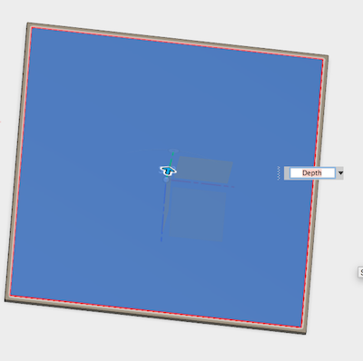
The lid of the box, demonstrating offset and extrusion
After this I had all the shapes modelled that I would need to cut my project. I exported all of the sketches as .dxf files so that I could open them in Illustrator and edit them to finalise the cut. After finishing in Fusion, all of my pieces looked like this:
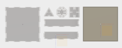
All of the pieces modelled in Fusion.
When the sketches were exported to Illustrator they retained the parts used to dimension the slits, this meant that I had to go through each ones and remove the paths that weren't required for the cuts that I needed. I did this by using the scissor tool to cut away the surplus lines. The sketches then had to be set to a 0.01pt stroke width in order for them to register as vector rather than rastor images. I also made a logo for engraving onto the top of my box, in Illustrator.
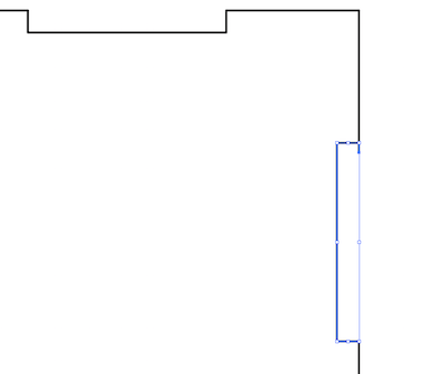
Removing surplus lines from Fusion sketches.
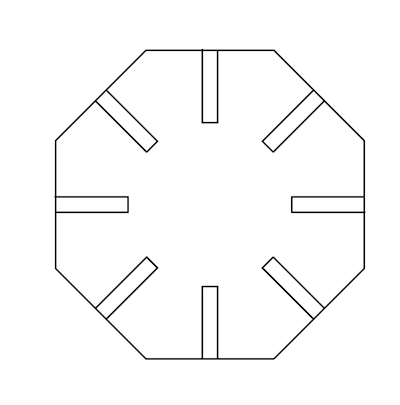
The lines are too thick here.

Correct thickness of lines to form a vector image.

My logo for engraving.
After removing the paths I saved each individual piece as an .ai file and began to start doing test cuts on cardboard to ensure that my dimensions were correct. The laser we hava in our lab is a 40 watt epilogue helix laser, if using another one the setting I have used would have to be altered accordingly. These turned out very well, so I moved on to cutting the mdf. I knew which settings were best for cutting mdf as we had worked these out in our group assignment, as well as things like setting the correct home for the laser. I made sure these settings were correct and then began cutting my pieces out. I made 15 squares, 10 octagons, 5 triangles and 1 of each part neccessary for the box.
My first cardboard test piece.
Cardboard test pieces fit together!
The settings I used for cutting mdf on our 40 watt epilogue laser.
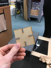
First mdf cut.

Built a structure from my octagonal pieces!

The triangles worked and fit with the other shapes well!

Net of the box, just finished cutting.

Box with lid. This was made to fit the box by glueing the smaller square of mdf to the bottom of the larger one, leaving room for the width of the box walls around the centre.

Box containing the construction kit. It was designed to fit 3x3 pieces which worked very well, this means there is room for more pieces if I wished to make any more or even if I wanted to make some different shapes.
Overall I am very happy with how FabPlax turned out, they fit well and all the shapes are proportioned correctly. The cuts could have been cleaner but for a prototype version of a product I don't mind the rougher finish of some of the pieces. The box did require some glueing but this would have been needed anyway in order to reinforce the sides so I m also happy with how this part of the project turned out. It's now ready to play with and make whatever you'd like!