Embedded Programming
Softwares Used
I was coming at this week as an absolute beginner, so deicded to focus on Arduino code libraries, they seem to be the most easily accessible form of programming that remains at a level of complexity useful for a maker or most D.I.Y projects. I started by ordering a knock-off Arduino Uno from amazon, the design is open source so all 'fake' ones will be almost exactly the same as a genuine Arduino model. I got this one, as it comes with a number of electronic components that I could programme using the Uno's chip and a number of tutorials on things such as light sensors and RGB LED's, the .pdf can be found here. I worked through these tutorials up until the 'digital inputs' one, which uses two buttons to turn on and off an LED. At this point I flt comfortable enough with the language to use it to programme my own board.
The Elegoo Tutorials
As you can see from the .pdf, the first two tutorials (0 and 1)are about installing the Arduino IDE (which I had done previously) and installing diffrent code libraries respectively. These are very useful for beginners who don't know how the software works, however you will not need any additional libraries for anything I'm doing on the page, or for any of the ELegoo tutorials in the attached pdf.
Tutorial 2 - LED Blink
This was the first tutorial I followed. It shows how to connect up the Uno and run the Blink sketch, most importantly it explains quite well how the different pieces of code in the sketch work and how they relate to eachother.

The 'Blink' sketch loaded from the IDE's basic tutorials. The Elegoo tutorial describes what happens here in greater detail. Basically, the pin is named and then set to turn on/off once every second.

The buttons at the top left of the IDE UI, the left one compiles and finalises the sketch, the right uploads it to the chip on the Uno.
Tutorial 3 - External LED
This tutorial shows how to connect up an external LED using a breadboard, explaining colour coding on resistors and how a larger resistor will cause the LED to be less bright.

An LED with large resistor (1K ohms).

An LED with small resistor (220 ohms).
Tutorial 4 - RGB LED
This tutorial shows how to connect up and edit the colour of an RGB LED. It uses this code to modulate the output to the LED from the Uno's pwm pins. The tutorial very clearly explains how the code works, explaining the initialisers and the looping functions that code the changing spectrum of colour coming from the LED.
An RGB LED running a colour spectrum from the example sketch linked above. Each colour (R,G and B) ramps up from 0 to 255 in their respective order.
Tutorial 5 - Digital Inputs
This tutorial uses two buttons to send 'PULL_UP' messages to the LED, turning on or off using this sketch. It is good for understanding how components and pieces of code interact with eachother as there is a very immediate and obvious cause and effect to what goes on. After getting this to work, I tried switching out the resistor to a light sensitive one, in order to create a circuit that was reactive to its environment, as well as having an on/off switch. This is a far more interesting application of arduino to me, being a sound/installation artist.

The sketch shows the PULL_UP messages sent when pressing the buttons and explains how they work
Turning on and off an LED using buttons.
I replaced the resistor with an LDR. The video shows the LDR dimming the brightness of the LED. I didn't alter the code, this change is made just by changing the analogue flow of current in the circuit.
After finishing these tutorials I felt comfortable enough with the arduino libraries and the IDE that I could begin to program my own chip. All I wanted to do this week was to get the on board LED to fade on and off.
Programming My Board
I first opened up the 'digital inputs' sketch (above) in the arduino IDE and editted it to work with the single button on my board. I then tested the sketch using an arduino. When I was happy with this I moved on to my own board. For this week I was using the 'hello world' board which i made earlier. The pinout's on the arduino are different to those on the ATTiny board, and the IDE does not natively support them. These were the first two problems I encountered. To find where to download the board libraries for the ATTiny I looked through Arduino's project hub and found my answer here. The url of the libraries -
https://raw.githubusercontent.com/damellis/attiny/ide-1.6.x-boards-manager/package_damellis_attiny_index.json
- must be added manually in the arduino IDE's preferences. You then install the libraries using the board manager, under tools. It is quite easy to find a pinout diagram of the ATTiny44 just by doing a web search, I will include it here for ease of use. The settings for every chip in the IDE are specific and can be difficult to get right first time, so I will walk you through each step for the ATTiny 44 below.
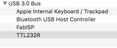
You should now check that your board works. Do this in the USB section of Mac's "system information". Here you can see both board and programmer.
YOU WILL NEED TO PROGRAM THE CHIP BEFORE GOING FORWARDS. YOU CAN DO THIS BY FOLLOWING THE INSTRUCTIONS HERE. If this does not work you will need to check your soldering and repeat.
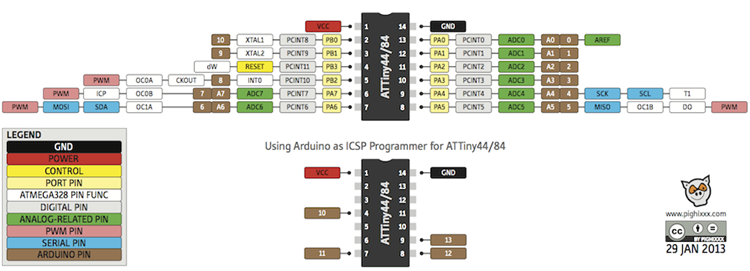
Pinout of ATtiny displaying how arduino pins relate.
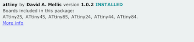
The first thing you will need to do in the IDE is make sure you have the boards installed (after downloading from the url above). To do this go into the tools menu ---> boards ---> boards manager and scroll until you see the above library. Click on it and press install. You should then see it as above, with INSTALLED written next to it.
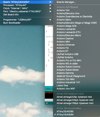
Next you must make sure you have the correct board selected. This is all in the "tools" menu.
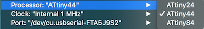
Now check that you have the correct chip selected under "processor". Use the internal clock that it show automatically.
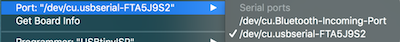
Now double check you are using the correct port and everything should be good to go.
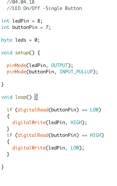
This is the sketch that I adapted from the Digital Inputs tutorial above. I removed the second button and inverted the second set of HIGH and LOW parameters. This makes it s that the LED on my hello-world board will only turn on when you are pressing the button down.
As you can see, the button works!!