Input Devices
Softwares Used
Prototyping Using Arduino
This week I wanted to create a board that I would be able to adapt for my final project, taking in and reading data from multiple bend sensors. These work like potentiometers, using comparative resistance to output precise values. But not reaching the stage of wireless output yet, as I felt this was too ambitious for one week and will probably make up the bulk of my final project work. I started by attching a bend sensor to an Arduino via a breadboard, following this tutorial to get an output back via LED.I then modified the code for my bend sensor, which contains two portions, for sensing the lower and upper bends in the finger. To do this I duplicated preexisting elements of the code to form another data stream, and added another LED to output to. The code can be found here.
Prototyping with the example code and one LED. Bending the sensor effects the brightness of the LED.
Prototyping with edited example code, two LED's and a split sensor. This is the kind I will be using in the longer fingers of my final glove, as they allow for finer degrees of accuracy in posture recognition.
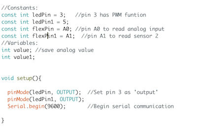
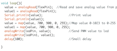
Here you can see where I added extra values and Pins to the code (those followed by a 1). I just duplicated the pre-existent code to suit what I needed it to do.
Re-Designing the Board
After prototyping with my Arduino I needed to make a board that was capable of performing the same tasks, but with multiple sensors, this would mean I/O lines if I was to use the same board for Output Devices week, which was the plan. This board will be a prototype of the one i will use in my final project, eventually encorporating at least 6 bend sensors, an RGB LED, a buzzer and the capability to connect to a Microbit controller which will be used for wireless data routing to Mi.Mu's Glover software. This is not currently available commercially, however I am working with thier team on integration of a D.I.Y. design and hope that some of the design features of my glove will be included in their final product.
The base of the board I am modifying this week is the Bueno-board, designed by my fab academy instructor Luiz Bueno, it is an Arduino Leonardo clone with a smaller physical footprint that runs on the ATmega32U4 chip. I will be editing the board to make one 10K resistor for each sensor, these will come in through analogue input pins 0-5, and a new 5 pin header for grounding each sensor which has been added to the ground trace. The resistors are standard 1206 surface mount size and the header is the same used in the original schematic, just copy and pasted to a different location on the board.
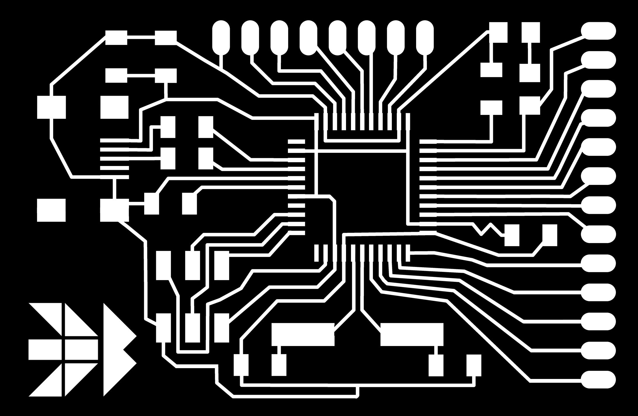
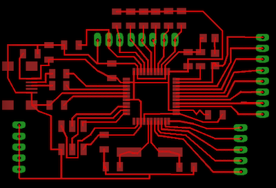
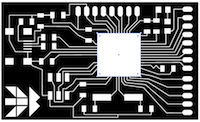
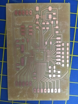
The traces on the original Bueno Board, you can use this .png to make your own, the full specs and components can be found on Luiz's website.
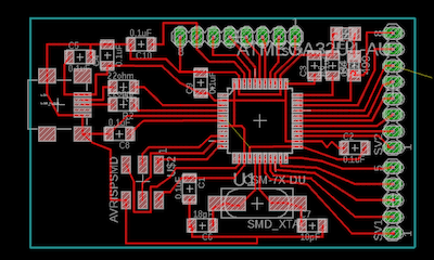
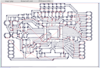
The brd view of the original Bueno Board, with component values. This can also be found on Luiz's website.
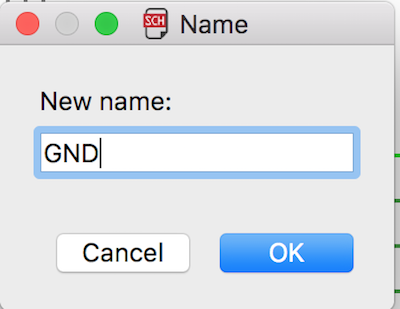
When opening the original schematic (which I will post at the bottom of this page) you can see that components are connected wirelessly, this makes the schematic easy to read. This is done by creating a non-connected wire from a component and then naming it to a pre-existing trace. Use the name tool and then type where you would like it to connect. This is how I connected the pins of my ground header to the ground trace.
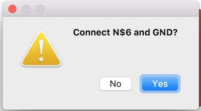
After naming iyour component you will get this message, just click yes and the traces will be attached.
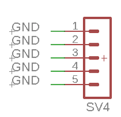
This is the ground header I added to the schematic. After performing the above operation to attch the component wirelessly, you must use the label tool to make each connection display next to each wire. Just type label, and then click the connections you have created through naming to do this. note: it is faster to do this in one go after all the connections have been made.
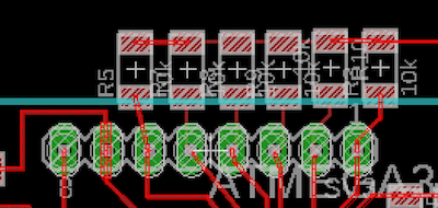
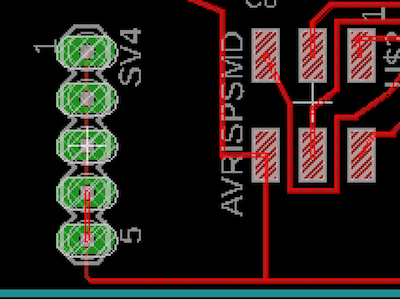
Here you can see all of the new components I added to the board, close up, the top pads of the resistors go to VCC.
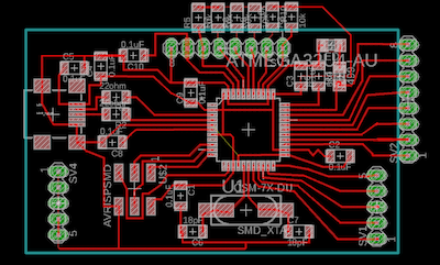
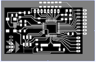
This is the whole brd view of my edited Bueno Board, it retains all of the original design, just has optimised functionality for the specific sensors I am using. I could have built the board and a shield to the same effect but this way is more compact, which is far better for the gloves I am planning on using it with.
Before exporting you need to remove unneeded layers from the view. This makes sure that only your traces and pads will be left on the board.
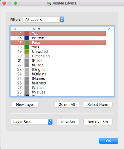
To do this go into layer settings and remove everything other than the top layer and the pads.
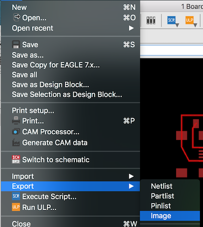
Now you are ready to export your image, instead of doing this the way shown in my Electronics Design week, we can try exporting as an image rather than printing as a pdf file.

Exporting this way allows you to select "monochrome", meaning you can bypass the previous photoshop stage as the image will export in black and white. You also need the image to be hi-res, somewhere safely above 1000dpi. Beware though, you will need to have a reference file when doing this as increasing the resolution will increase the image size. This can be done by printing .pdf file as well as exporting this way if you don;t have access to a reference image.
Exporting, Milling and Soldering
The next thing after exporting from Eagle was to correctly resize the .png in Illustrator. The first method I used for this was covering the chip pads with a white square, acurrately drawn to the correct size. This method DID NOT WORK. IT wasted material as the whole board came out too small, this may have been because I wasn't accurate but everything seemed fine as I was doing it. The safest way to do it is to make one image tarnsparent and then overlay them, exactly matching the pads for the ATmega. I then exported to fab modules, using the correct settings for my machine to draw toolpaths. I saw that there were two chip pads that the machine wouldn't mill properly and this was okay as it would be easy to separate them manually with a scalpal. I therefore saved the files from mods and sent them to VPanel for milling. After milling I cleaned the board and soldered on the components, testing for shorts with a voltmeter as I went.
This was the method I tried using the square. I would not recommend it but image is for reference.
This method worked much better, as you can see, my board floats obve the top of the original in Illustrator and the pads are exactly the same size.
IMPORTANT
After doing this you must create a white square with 1mm black outline exactly the same size as the board. This is what you will process in mods to form the .rml file for cutting the board out of the larger pcb sheet you mill from.

These were the settings used for the traces in mods. To import an image, just click input format --> image. To create an .rml, click output format --> Roland Mill. For the traces use "PCB Trace 1/64". When you are happy with this click calculate and the toolpath will be drawn.
This is what the traces toolpath created in mods should look like. If you are happy with yours click save and the .rml will download.
The settings for the outline are slightly different.
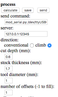
As well as changing the top set of settings you must also change the tool width to 1mm here, as well as the number of offsets to 1, otherwise the machine may affect the traces you will have already milled from the PCB.
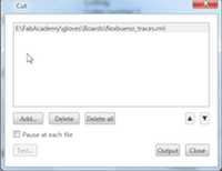
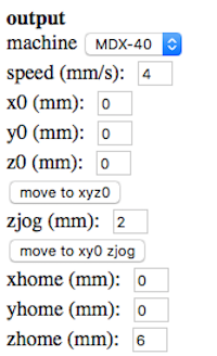
Once you have your .rml files open up VPanel. Press the cut button, make sure to delete any files that may already be there and then add the traces.rml file. After this has milled, remove this one and add the outline one. They will begin milling as soon as you hit output so make sure you have zero'd the machine and have selected the correct tool (2 for traces and 1 for outline) as detailed here under "milling the board".
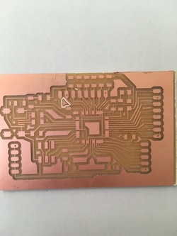
The board after milling, it still needs cleaning and the connected pads separating.
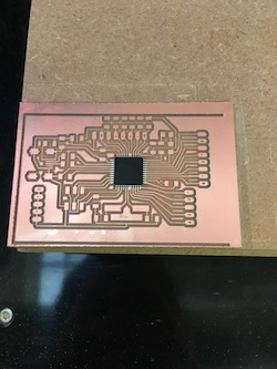
It's the right size! The best way to check this is shown, just place the chip on its pads and see if it lines up.
Clean the board, carefully scraping of excess copper with a scalpal. This will minimise the risk of shorting when soldering. The board is milled!
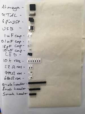
All of the components I need for the board ready to be soldered. The full list can be found on Luiz's website.