Mechanical Design
Softwares Used
Designing a Kinetic Sculpture
For our group project this week Jedd and I decided to build an oversized swinging stick sculpture. It will be around 60cm tall, which is the longest length we can cut using our laser, and eventually actuate through pulsing a fabricated electro-magnet at the base, which will repel magnets attached to each stick. We are also thinking about making it reactive to an outside condition such as light or temperature. Our first steps were to look at various different kinetic sculptures to try to better understand how they work, after this we decided to use Fusion 360 for the design process as we are both comfortable working with it. We also decided to make the sculpture out of mdf as it's not too heavy and we have a lot of it in the lab.
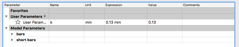
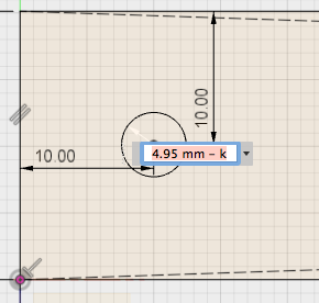
I utilised Fusion's parametric capabilities so that if anybody else would like to make this, they can account for the kerf of the laser they are using. Just edit the equation!
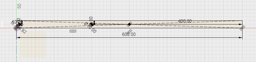
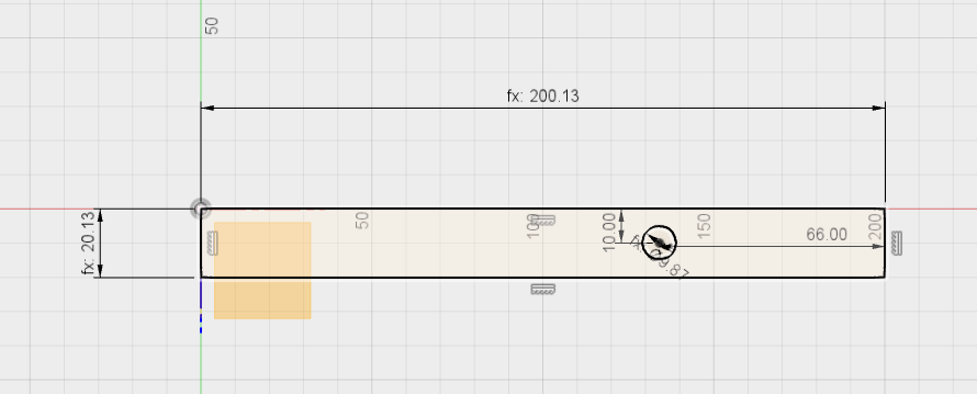
I then started by designing the longer bars in fusion, here you can see the sketch with dimensions.
The hole for attching the shorter bar sits square at the end of the longer one, meaning there will be no overlap.
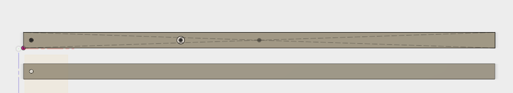
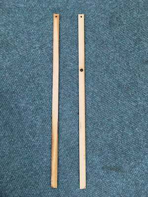
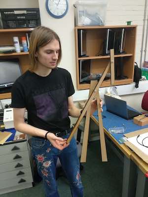
Here you can see the two longer bars. One onlyhas one hole as this is the one that will be facing outwards. I did this as I wanted to press fit with the bearing that will sit in the larger hole of the first bar, so that the outer face was clean and looked nice, however, as you will see later on this was not possible.
I then designed the shorter bar, making a third of the length of the longer one, which according to the rule of thirds, should make the sculpture aesthetically pleasing.
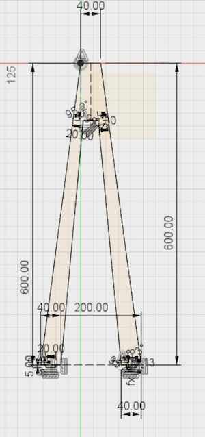
The last thing I designed was the stand, this was because I knew exactly where the hole for attching the longer bar would be, as well as the length of the shorter one, so I could account for this in the height of it.
I then used the "move/copy" tool in fusion to make a copy of the stand and added a sketch, placing a 5mm hole in the center of the top of the A frame.
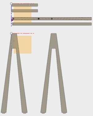
Here you can see all of the parts ready for export from fusion. After finishing in fusion I exported the dxf files, opened them in Illustrator, nested them as best I could for the bed of our laser and sent them to cut.
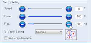
These are the settings that I used to laser the mdf.
Assembling the Parts
Next I had to assemble the laser cut parts. An issue I had after cutting was that our laser has a 'quirk' where it doesn't move all the way to the left, this meant that although i designed the parts to fit exactly to the bed, when zeroing the laser there was a small offset. This meant that the tabs for the stand didn't cut, I will have to design the box accordingly. The first stage of assembly was to glue each half of the parts together, I did this using pva and then pressing the parts over night. The next was to fit them together. Unfortuntely the bearings I was using weren't exactly 5mm in diameter. This meant I had to drill through the front of my different parts and use bolts to attach them together. Whilst this isn;t the most aesthetically pleasing thing in the world, it does work as I intended! I then glued the magnets to the end of each stick. Next week we will make an electro-magnet and stand for the electronics to go in and program the sculpture to react to it's environment.
Other than the stand, the parts lasered well.
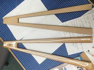
Glueing the parts. OI layed them on paper to avoid getting glue all over the workbench and applied liberally to one half.
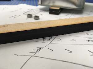
I then pressed each half together being careful that they were correctly aligned, wiped off any excess glue and placed heavy books on top of them to make sure they stuck well. I left them overnight.
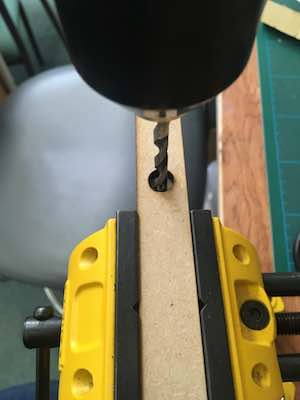
I had to drill holes through the parts i intentionally left flat, this was annoying, but bolts were required to attach them.
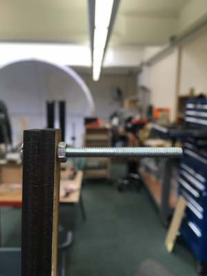
The bolt ready to attach the arm to.
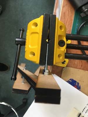
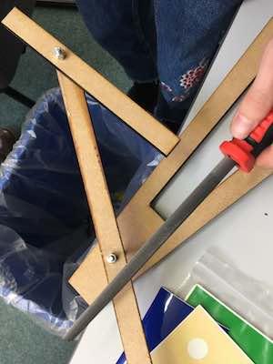
After attaching the parts I clamped the bolt and cut off any excess with a hacksaw.
I filed the end of the bolts to remove any sharp metal edges.
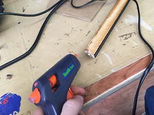
I then used a hot glue gun to stick strong neodynium magnets to the end of each bar.
The physical part is finished!
Here you can see the sculpture swinging with not too much force applied.
Next week we will ebe automating the sculpture with a strong electromagnet, which we will make ourselves. We will also make the sculpture sensitive to a factore such as heat or light, affecting the swing speed by modulating the power of the electromagnet, which will repel the neodynium magnets attached to the bars. We will also be making a bse to stand the sculpture on top off and to house the circuitry that will be required.