Week Four
cut something on the vinylcutter design, make, and document a parametric press-fit construction kit, accounting for the lasercutter kerf, which can be assembled in multiple ways
Laser Cutter
Laser cutting is thermal separation method which can operate with immense precision. Various materials can be placed inside the cutting machine on the bed without being fixed and designs can be passed from a computer using a print function to either engrave Rasterized images or follow vector paths. The simple yet elegant process of this machine instantly grants it as one of the most versatile in the lab and subsequently the most popular.
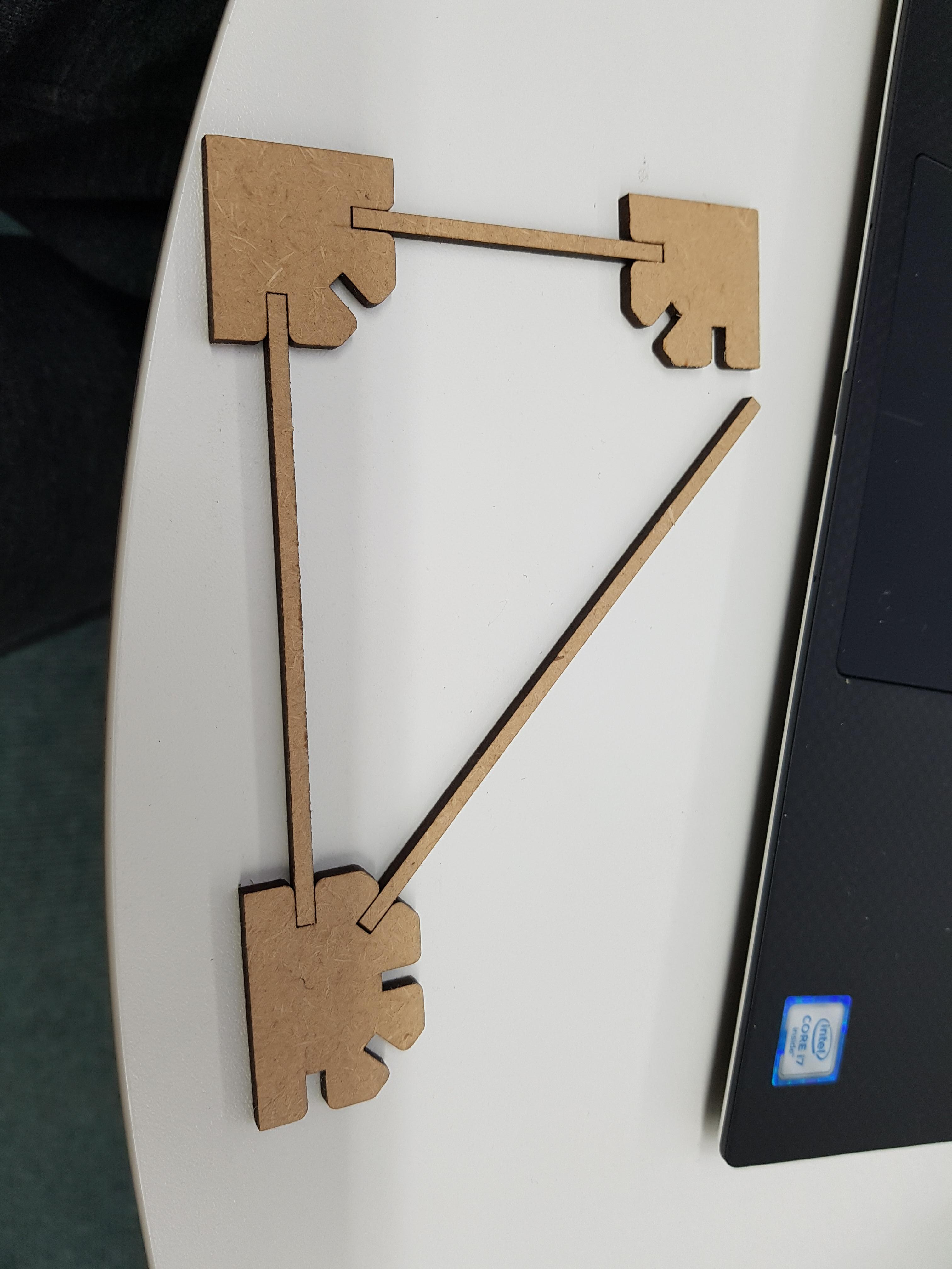
One of my tasks this week was to create a press fit construction kit, with a parametric design file. This demonstrates a rounded knowledge of this process and is a good foundation to begin more complex works. I designed parts that can complete basic structure triangles implemented in truss design with the objective to build a model bridge across a small gap, a task I know as the initiation into many design and technology courses from primary school up to the highest levels of education. However, the kit should be flexible enough to try and build whatever you want.
Initially I began working with Rhino 3D and the plug in Grasshopper to generate parametric equations, Grasshopper’s node based visual programming interface is rather attractive and as I had worked in Rhino with my last project this seemed like an obvious choice, but instead I chose to work with Fusion 360 purely to expand into something new. As I have stated before I have had some common advice that one CAD program does not differ far from the next, at least when you are in the early stages of programming as I am and not yet branching out into animation, simulation or rendering.
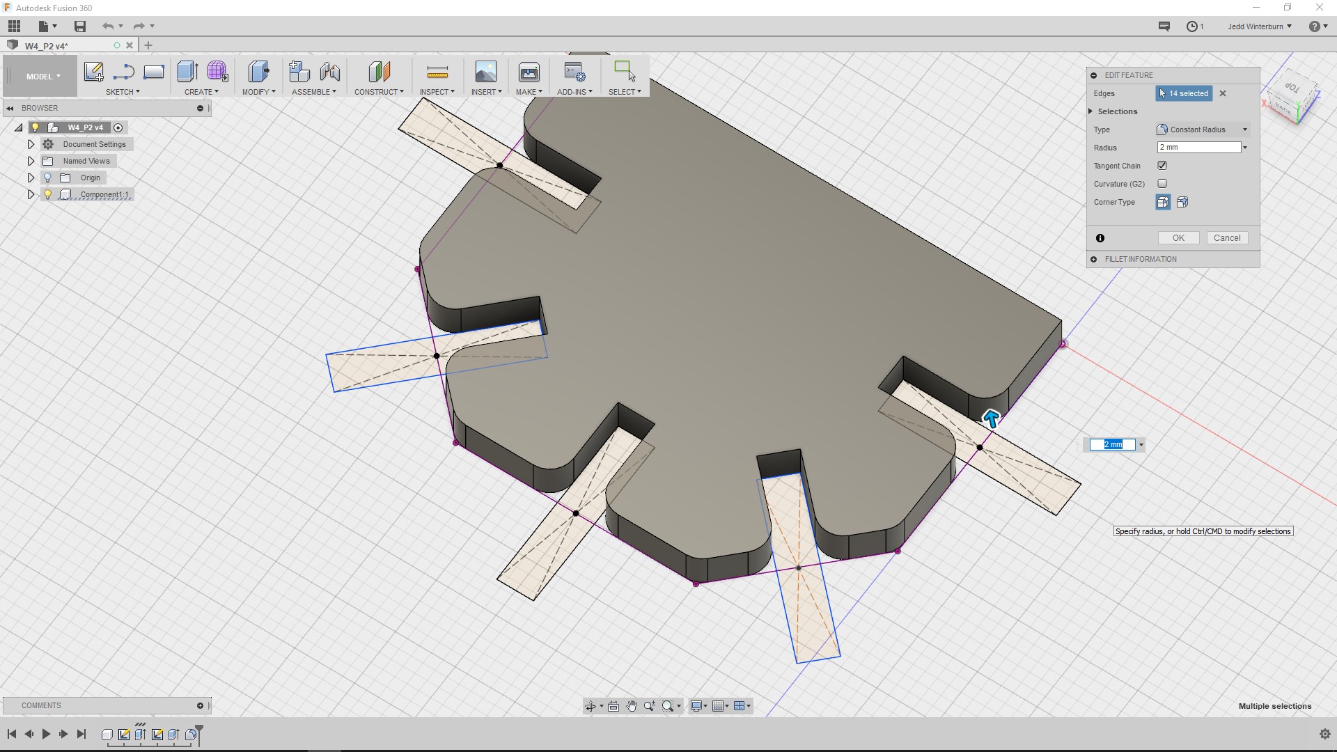
Fusion 360 has a very intuitive interface which seems to be under frequent development, so much so that it is hard to find a tutorial that works with the same GUI shell, which is a good sign. The parametric modelling is very easy to define on the fly when compared to Grasshopper with ‘constraints’ that can be attached to geometry with two easy clicks. When looking at the back end It seems as if my choice in taking the harder option indulging in new software actually turned out to be blessing in disguise, with the ability to tie in coeffects and then constraints in a much more applicable way. The only inconvenience I see to this technique when compared to one like Grasshopper is the fact you could not extract and reuse the math systems that have been defined.
Not only can complex, parametric geometry be generated visually on the fly, but an object can be edited from anywhere in the timeline of the piece. This feature may add some paradox errors which are hard to trace but just goes to show how flexible Fusion 360 is.
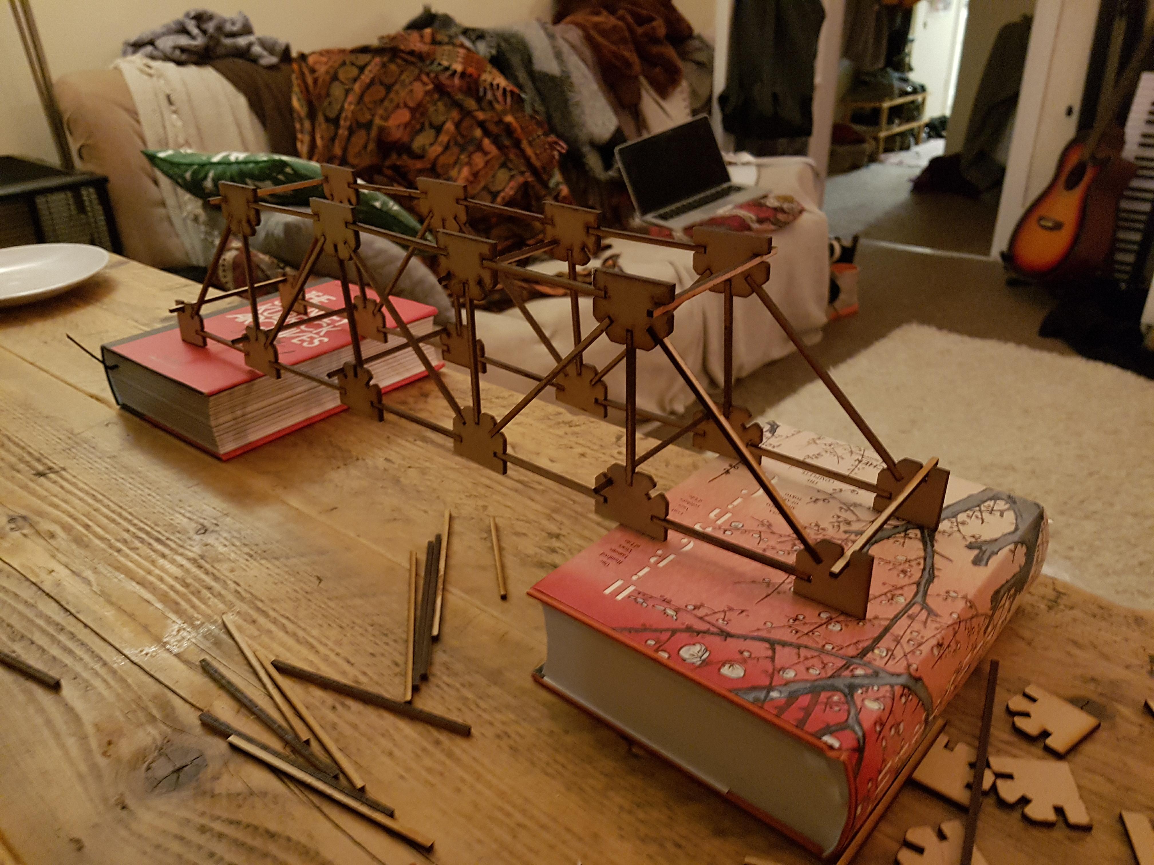
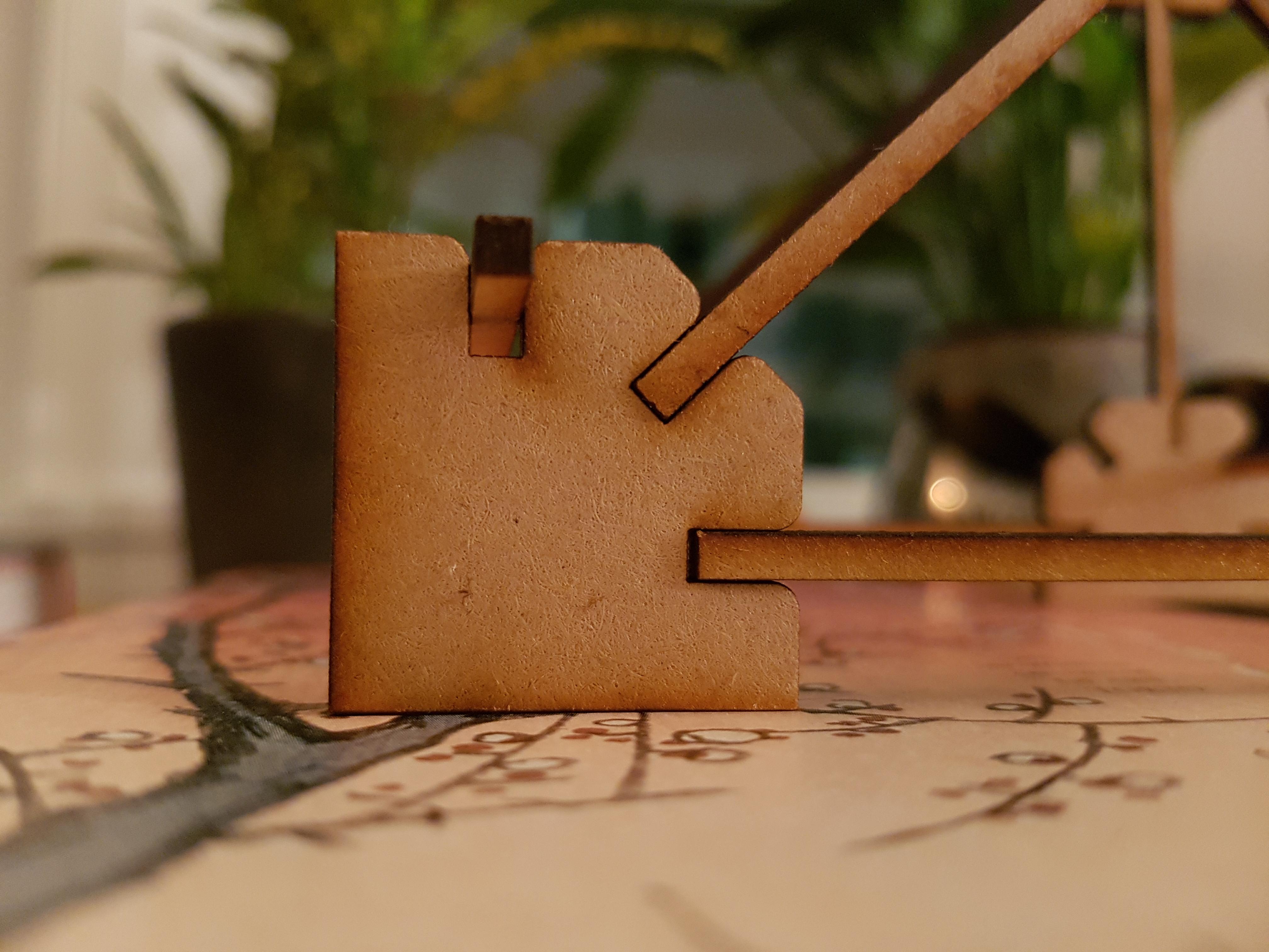
In my project, I only worked with two lengths of rail and two types of hub. The hubs can fit the width of the rails, which is defined by the thickness of the material being used. The slits can be modulated by changing the coefficient used to define the material thickness, along the kerf compensation (for our machine it was 0.12mm) which changes depending on what machine you are cutting with. Sadly the dimensions of the board I was using were not consistent which to joins had to be made on cut sides but the process did work well.
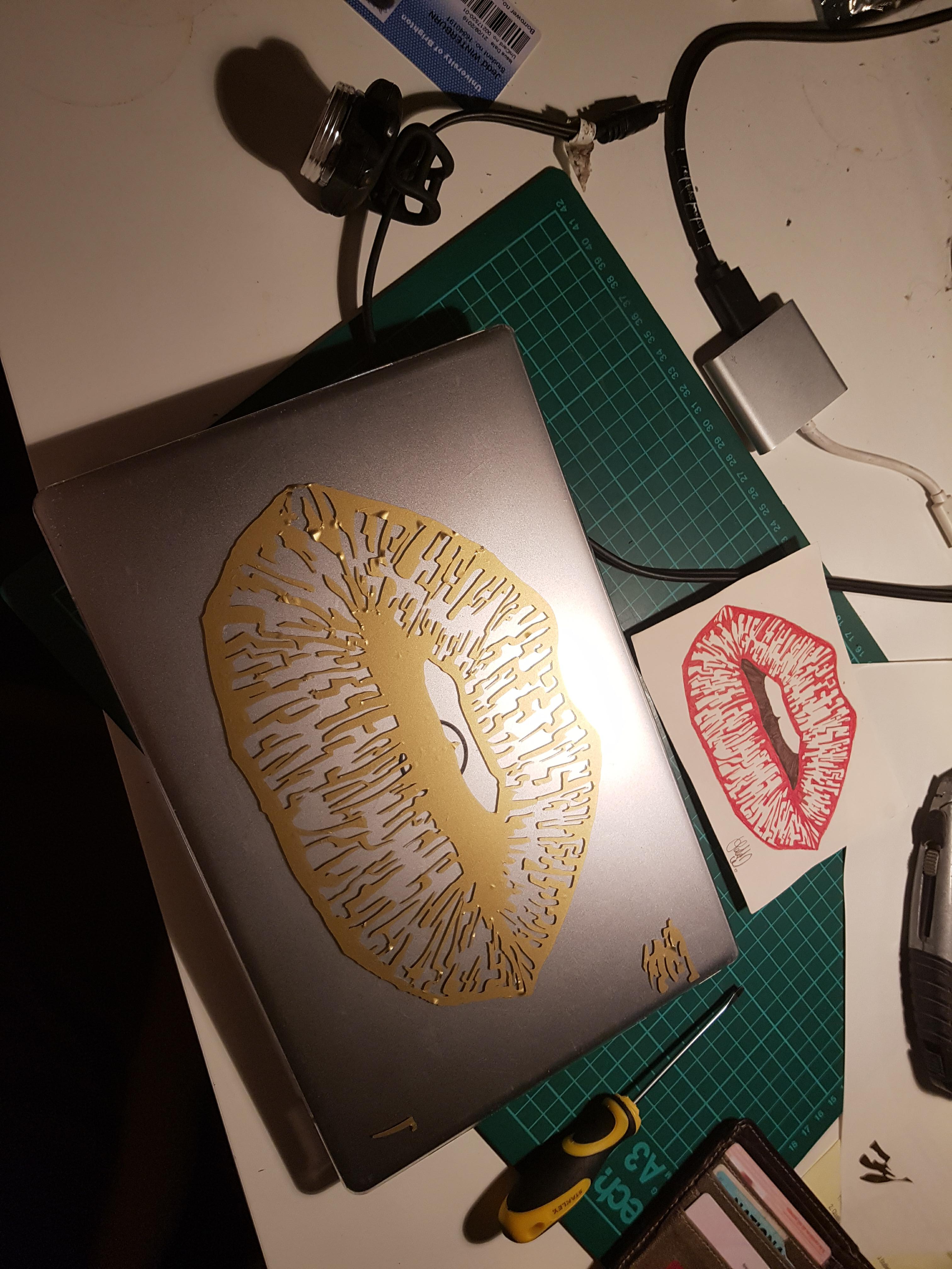
Vinyl Cutter
A vinyl Cutter is similar to the laser cutter but more primitive, only working on one axis and physically cutting the material with a blade with 360 degrees of rotation. The machine reads the dimensions of the material passing through it and can cut Vector images passed from a computer. I demonstrated this machines capability by cutting a simple sticker for my laptop but it can be used for a lot more and I intend to further my documentation here in the future.