what is a machine?
"an apparatus using mechanical power and having several parts, each with a definite function and together performing a particular task."
Our group project page can be found by clicking the image below.

We split the mechanical design up into separate tasks, where I took on the design of the gondola that holds the pen.
First however we all looked at current Polargraph designs to get inspirations and see wha design challenges were faced.
Looking online there are several different designs that have been used by the pen holder. One aspect that seems common is that almost all of them have some sort of face plate. We can’t find any explanation for this, but we guess it might be to stop the holder losing balance and falling over.
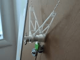
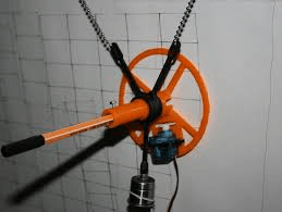
For the attachment to the chain I will need to have rotating pulleys to create a V with the point of the V being the pen tip. Adding bearings will allow the angle of attachment to change in accordance with the position of the belt.
Some of the more advanced designs use a servo motor to lift the pen off the drawing surface so it is possible to move across the board without leaving a mark.
It appears weight is important to have the pen sit against the drawing surface rather than swing about or drag along the surface. This seems like a pen/size/system dependant calibration using trial and error. It is important to make sure the wight is even on all sides of the gondola.
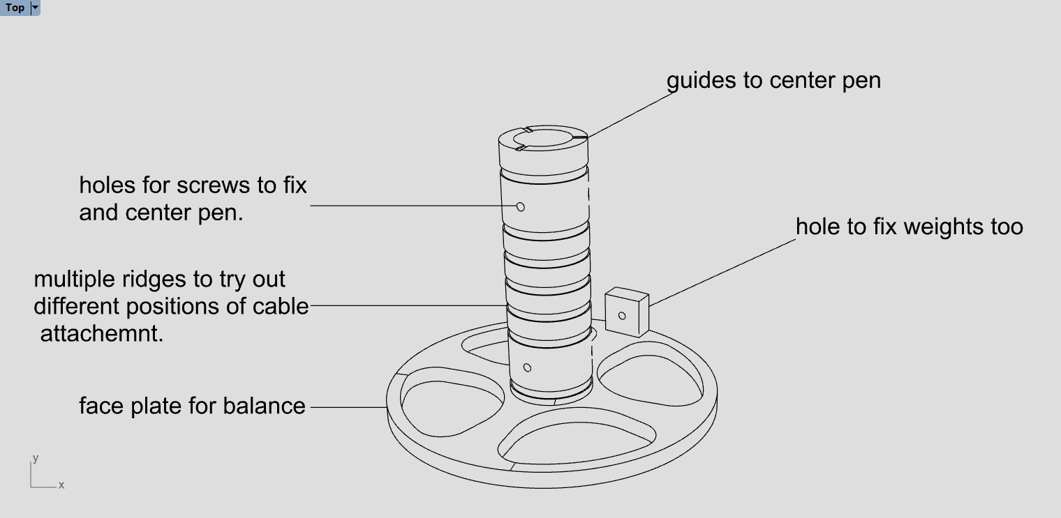
Attaching the pen will require a central hole with three thumb screws to center. This will allow for different pen thicknesses and ease of removal. The surface will also be important in designing the gondola, vertical or sloping? Vertical will allow for more accurate drawings over the whole surface, but it will be harder to calibrate and will depend on the sprocket-wall distance
Sloping will could potentially give less accurate drawings at the extremities, but will be much easier to calibrate.
Using 4 cables could allow for greater accuracy and ease when using a vertical surface. It could also allow further development to create a cable printer if turned 90 degrees.
Prototyping
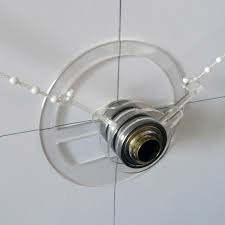
With the above in mind, the initial design was created and 3D printed on a Creality using cura to generate the g-code.
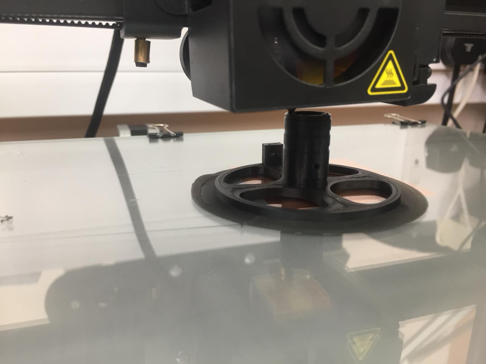
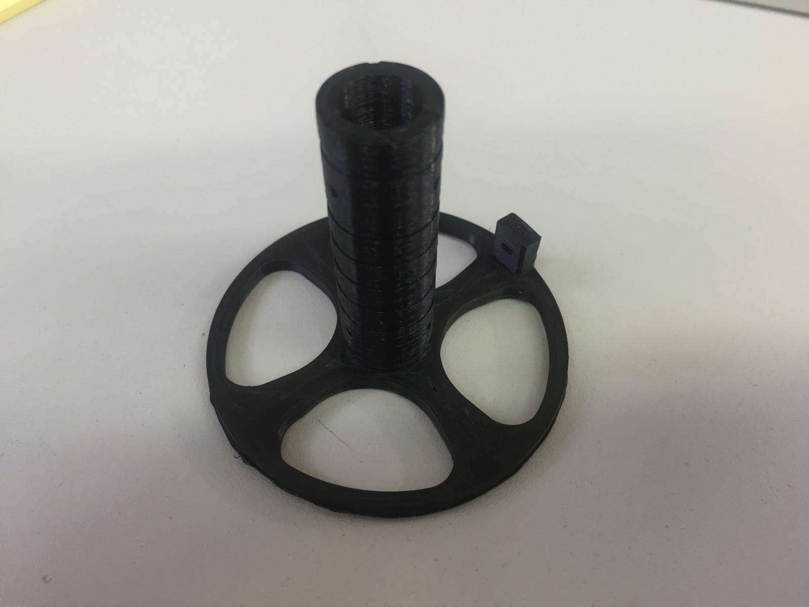
Immediate feedback was that the holder was too small - it would be nice to fit other larger pens in with a larger central bore, which would still allow for smaller pens if we wanted.
We also need to think about how the cables will attach to the gondola in more detail.
Creating the face plate was the most time time-consuming part of the print, so to prototype faster this will be left out of the next iterations, it will hopefully also show us why it is we actually need one in practice rather than us just guessing.
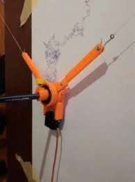
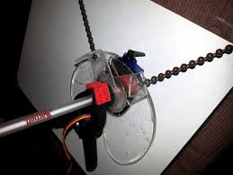
Three further designs were tested:
It was the third design here that proved to be the star. Printed on a robox using automaker (with cura algorithm) for slicing allowed this piece to be printed in one and have moving parts. It was very exciting to remove the supports and slowly reveal the rotation achieved. We had a test draw, moving the cables by hand trying to follow, what else, but a picture of a penguin.
The design definitely required some improvements and Andrew continued refining the design in the next week.
Week 2
As Andrew and Sophie continued with he mechanical working of the machine, I dived into the control.
I have experience using grasshopper to generate gcode and found it a very effective way to read polyline geometry.
The first task for this was to understand the geometry and variables of the machine, then to calculate the cable length with the gondola at a certain point.
To do this I used the Marginally Clever website.
Once our machine geometry could be read and any point along the curve it was a case of reading the values at subsequent points and finding the difference from the previous value. Once I had the difference between each point on a curve, I cumulatively added these so I could use absolute coordinates on my machine and add the relevant "G", "X", "Y", "F" value.
I had a play with using the HumanUI plugin for grasshopper. This allows us to create a more user-friendly interface to control the generation of gcode. The "spaghetti jusntion" of wires can sometimes be intimidating to those not familiar with grasshopper
We will be using a program called Marlin which has a specific ‘Flavour’ of Gcode. Some of the commands we have looked at are:
We would like to add a servo that would lift our pen off the drawing surface and enable us to draw with less limitations, but we were not able to get the M280 command to work.
Marlin
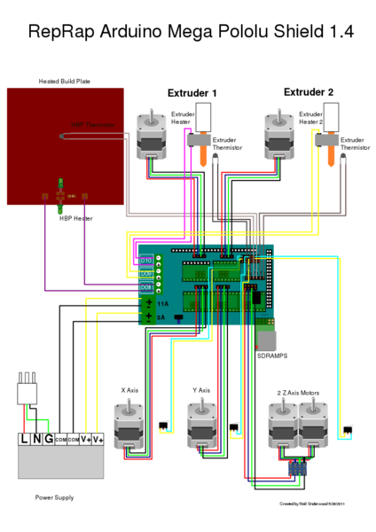
I uploaded the Marlin firmware onto the Arduino Mega which can all be edited and uploaded using the Arduino IDE. The RAMPS and Marlin firmware are a bit overkill for our purposes, as they are designed for 3D printers that could have multiple extruders. We knew we were going to use two NEMA 17 stepper motors to rotate our bobbins based on their range of motion and accuracy. The hardware/firmware combination is very comprehensive and powerful hardware/firmware combination which also means there is a lot of documentation.
One of the main values we had to change in the configuration.h file was the ‘steps per unit’. This will change depending on the size of the pulley and belt we use. I can get this value from my grasshopper script. I initially forgot about microstepping (limited by the driver we use - pololu a4988 gives 1/16th microstepping), but once factored in we got the correct value and the machine working. Using this linkwas good to check my calculations; at the very bottom of this page there is a super useful link to calculator developed by Josef Prusa for calculating the movement setting values for both threaded rod and belt driven axis.
RAMPS 1.4
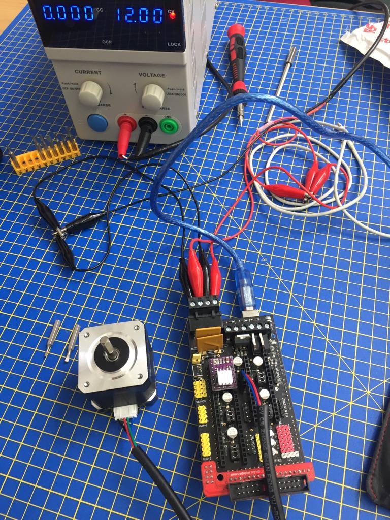
This board sits atop our Arduino Mega. It is a shield that enables us to easily add our stepper motor drivers (we used Pololu A4988) and connect our two NEMA 17 steppers. To connect a servo we need to switch a jumper to power the servo circuits. These are near the 12V power input. A basic setup can be seen in the image below.
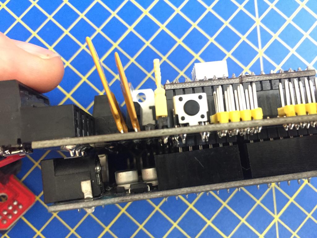
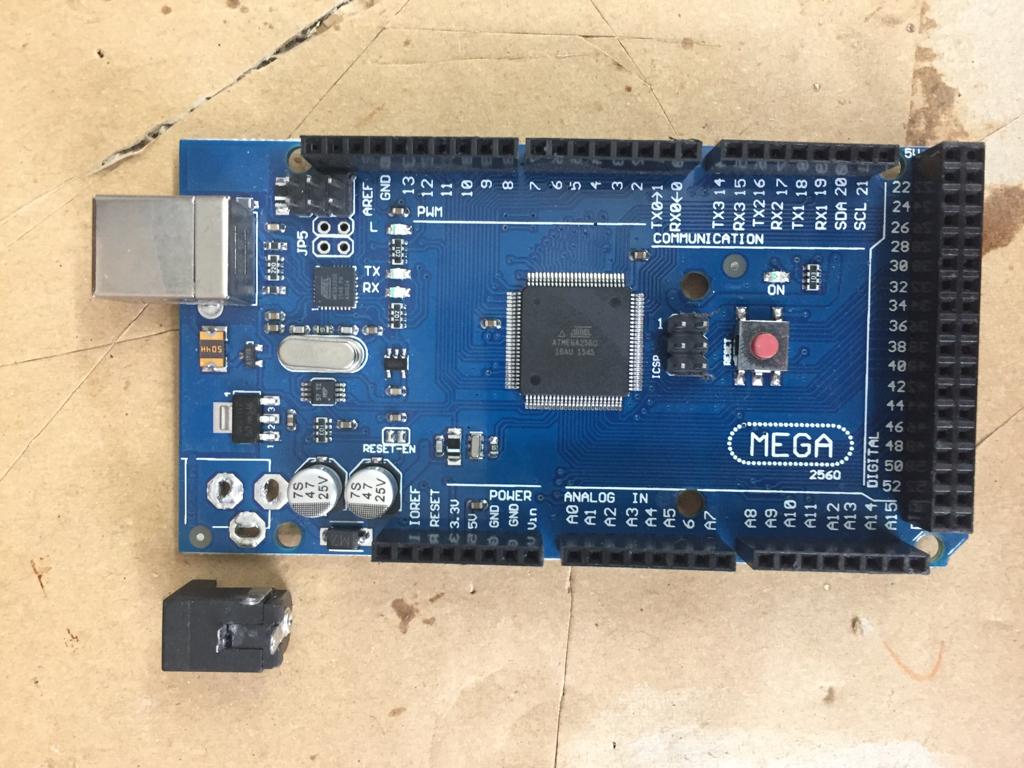
We removed the barrel connector from the Mega as it seemed to be getting in the way of the RAMPS fitting properly on the Mega board.
We were having issues at first using drv8825 drivers rather than the a4988 drivers. This gives us a lot greater control allowing 1/32 steps! Unfortunately there were some issues reported with some makes of motors, I didn’t get to the bottom of this, but when we tried the a4988, we had no issues at all.
Interface aka Pronterface.
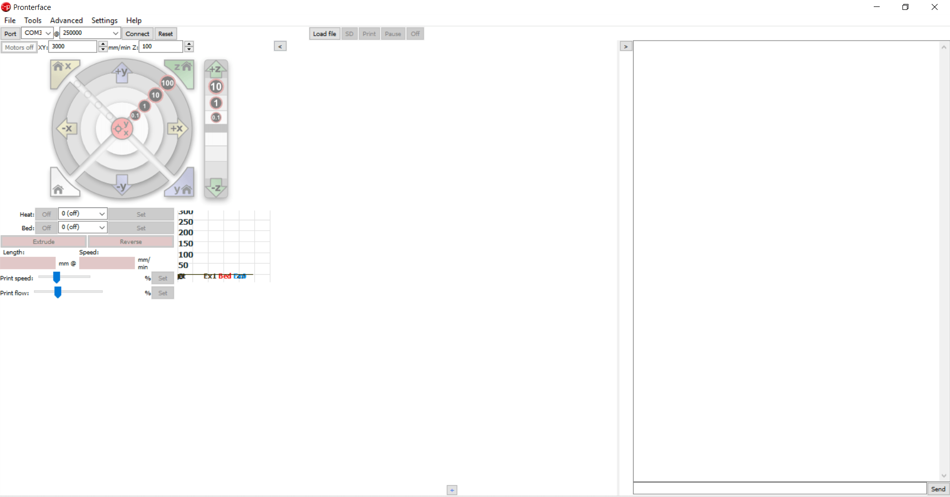
A standard and commonly used interface for the Marlin/Ramps combo is a program called Pronterface. It is very simple to use and easily connects to the Mega setup when connected.
The wiki is here, but you can download a package so you dont have to worry about installing the individual programs to run it.
The grasshopper code creates and saves out the gcode to a .gcode file. Using pronter face it is just a case of opening the file and clicking print.
Creating drawings
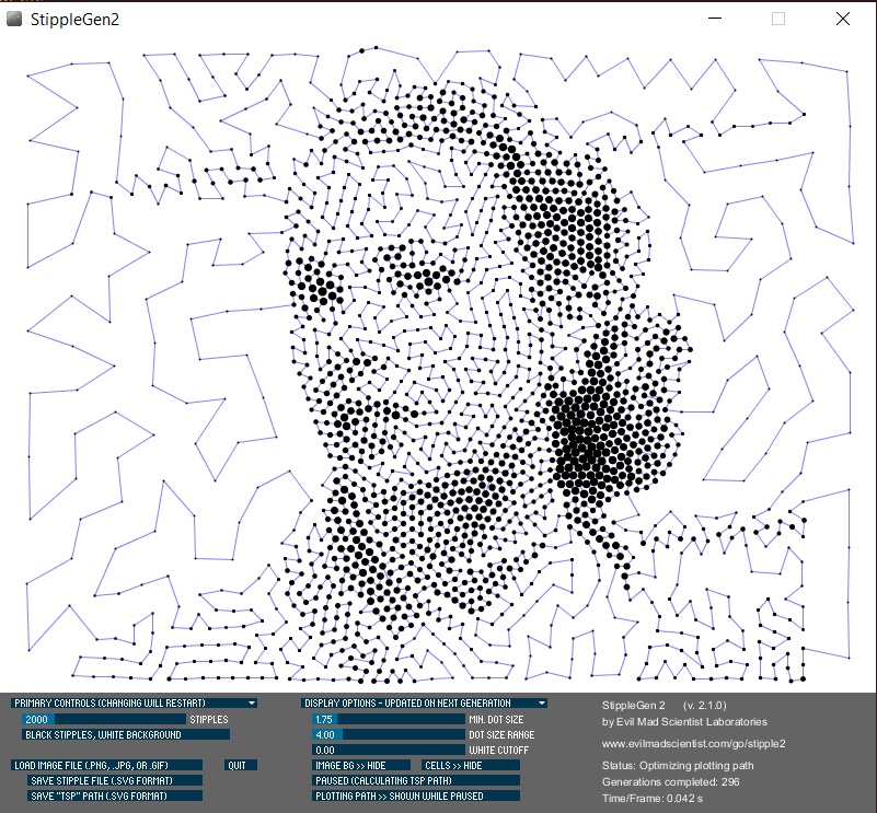
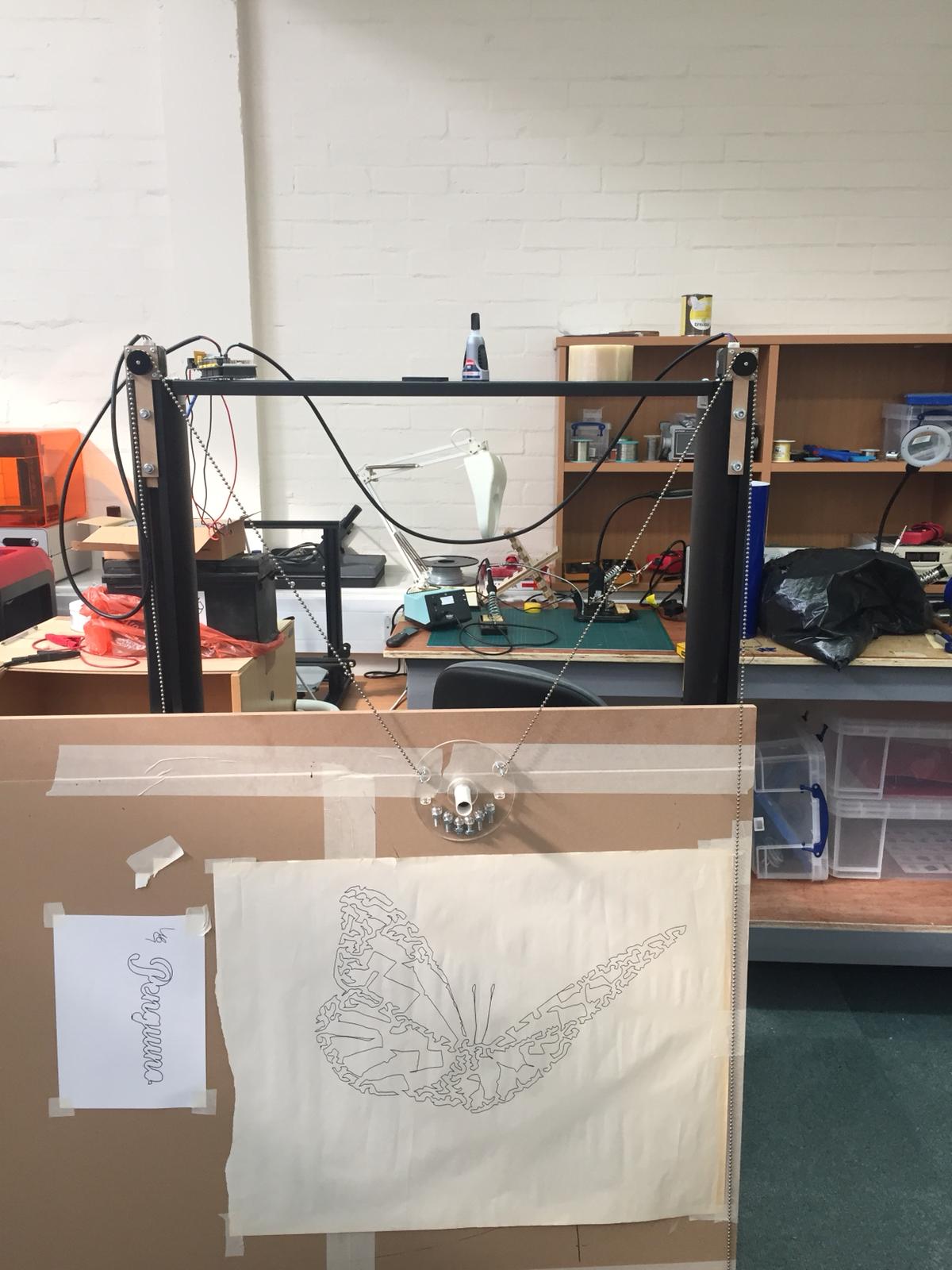
The limitations of our machine meant we could only draw a single continuous line. We created a few test files to measure accuracy, repeatability and if any accumulated errors were in our file, but all the drawings were pretty simple. We found a program called Stipple gen 2. This program takes an image, applies points based on grayscale, from this a voronoi diagram is created which then creates a new set of points and subsequent iterations refine the distribution. From this it is possible within stipple gen to run a Tradesperson shortest path or ‘TSP’ algorithm which creates a single line across all the points (in theory in the shortest path) This is how we created the butterfly picture below.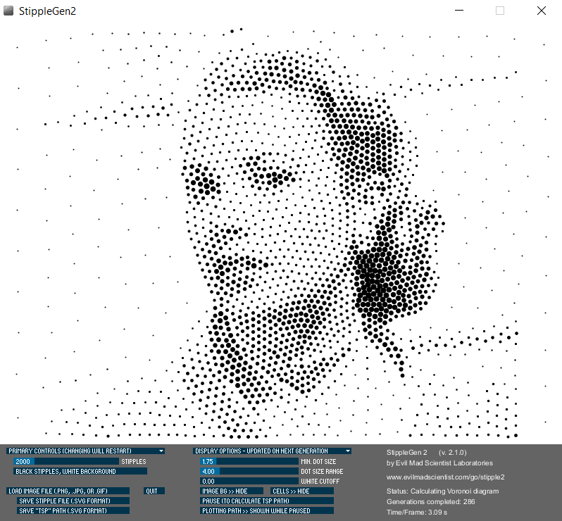
And finally some videos and images of the machine in action showing what we can produce. The "First Circle" was the proudest moment.