Electronics
Pauduino
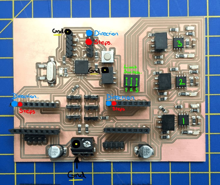
Having managed to create my own version of an Arduino this year, I used that for the final board. For each of the drivers/axis of my robot I only need 2 pins to send the information for the number of steps and the direction of the stepper motors, so with an Arduino, I can in theory drive up to 10 motors, which would be more than enough for every axis I require. Of course I need other pins for different functions, so I may need to upgrade my board as this develops.
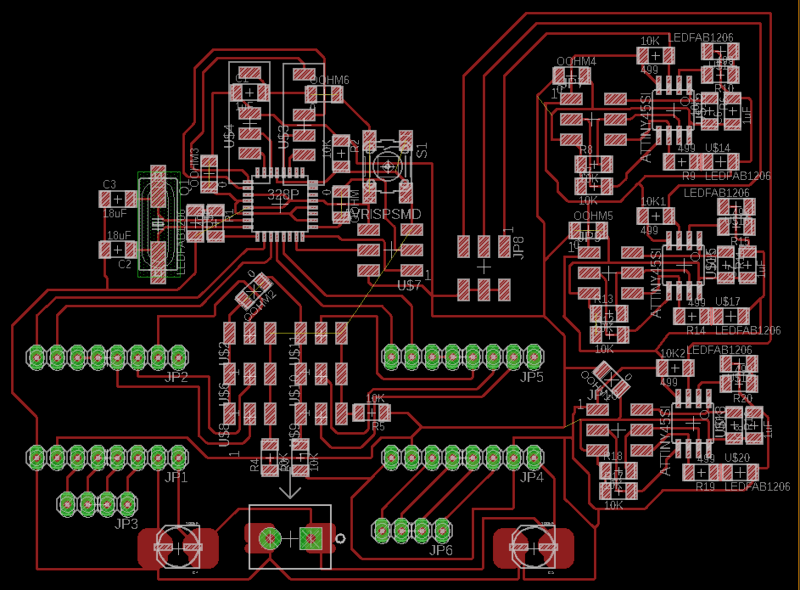
Eagle Board.
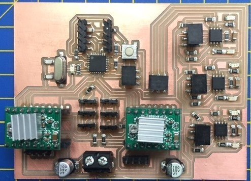
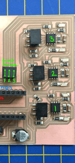
Populated Board with Pololu Drivers.
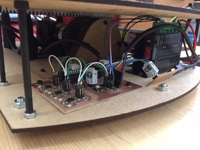
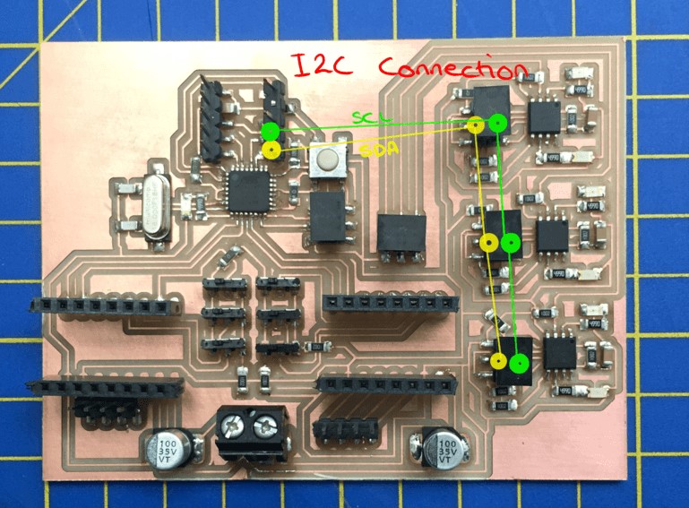
Board in situ with I2C connections.
Microstepping
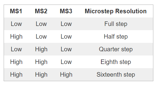
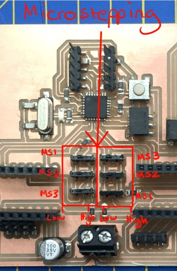
My board can achieve mircrostepping with the Pololu drivers (the top step and direction pins are for the larger tb6600 stepper driver required for the NEMA 23 - this can be interchanged with a Satstep board) using the 3 switches on the board indicating MS1, MS2 and MS3. The microstepping required can be seen in the pictures below.
I2C
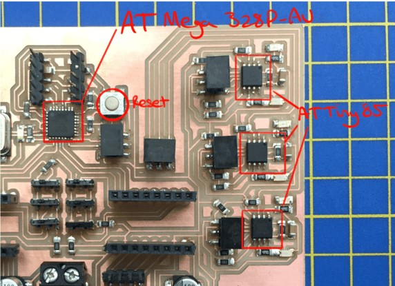
I am using I2C communication for the stop switches. In this way I could have up to 128 stop switches using just two pins ( a little over the top), but the pin saving is tremendous for the 6 I will eventually need. For this I connected the SDA and SCL pins of the AT-Mega 328-P to the same on an AT Tiny85. The 85s are in turn connected to a button which changes the boolean being sent to the main board when pressed.
For future development I realise I will need to increase the memory of this board considerably to contain the lists of 'steps' and 'directions' required for fine movement between points. (At the moment I can achieve approximately 2-300 items). I have looked at using an External I2C EEPROM chip, which would certainly address my memory requirements and also not use any extra pins as this will be on the I2C line, however, this appears to be more for storing data collected from the Arduino and I am not sure how I would upload directly too it.
The other option is using a memory card. There is the obvious ease of use with this, but it requires SPI communication, taking up 4 pins (MOSI/MISO/SS/SCK). This will still allow up to 7 steppers and the speed of getting the data is much faster than I2C.
Mechanics
Based on the AR2 I started to put together a rough idea of how I hope the move the joints to work in Rhino.
I spent a lot of time developing the 3rd and 4th axis so I would know the weight of the arm and could adjust the power of the earlier motots accordingly. I used planetary gears for increased accuracy and greater torque.
Unfortyunately I didn't have time to fully realise the later axis for the presentation, but I did manage to get the first two programmed and working.
The engineering department was having a clear out, and daily treasure hunts to the trip turned up some interesting parts that I used. Mainly these two large gears that I ended up using for the first axis.
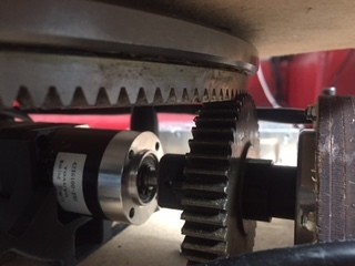
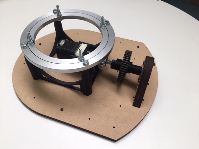
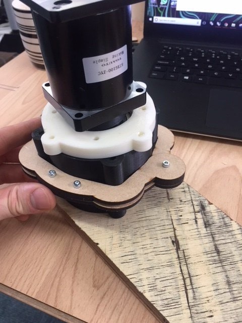
I combined these with a 'lazy susan' (the mechanism often found in the middle of tables at chinese restaurants) bearing and a 3D printed/laser cut platform to hold it up. This initial axis was controlled by a NEMA 17 and 1:42 planetary gear.
Gears and Bearings
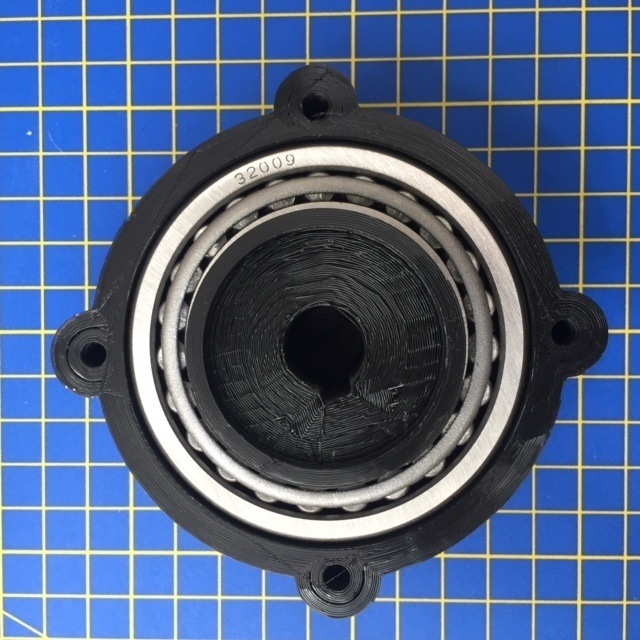
For the Bearings I used Tapered roller bearings. This type of bearing is intended for handling axial and radial loads as which I will experience in my arm. For the second axis, I used 2 facing opposite directions to better handle the radial load. For the initial axis, this was not necessary, but I had this type of bearing available. A more suitable bearing would have been one that uses ball bearings, potential sealed to keep dust and dirt out of the mechanism.
I used a couple larger gears described above, this was as they were available and to translate horizontal rotation into vertical rotation. I could have also used a belt system as well. To get the torque I required at each stage I used premade planetary gears bought from china. These were 1/42 on the first axis and 1/100 on the 2nd axis Nema23. When seeing the movement of the first axis, my calculations were not correct - this was eventually put down to the 1/42 gear not being specified correctly and I had to put in an error factor which fixed the calculation and gave the desired movement.
3D Printing
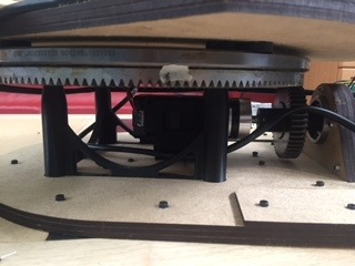
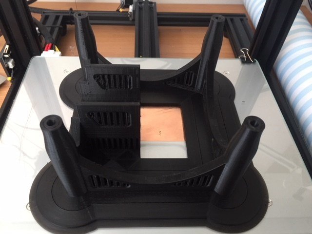
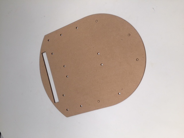
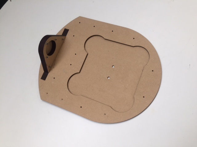
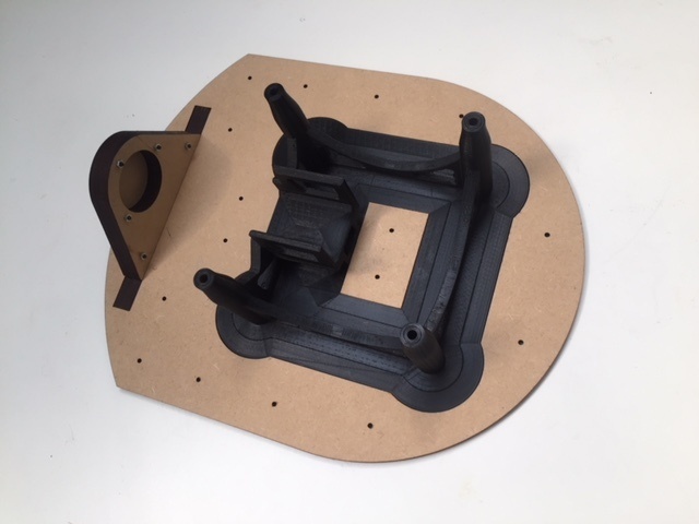
I 3D printed the base of my roobot that housed the first axis stepper and held up the lazy susan and large grears. It was a joy to design and one of the largest prints I have ever done taking 19 hours in total - fortunately no problem for our creality. It did the job perfectly first time and you can see how the base is built up in the following images with the laser cut MDF parts.
.JPG)
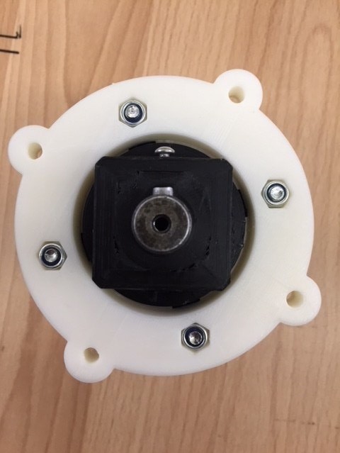
I also 3D printed the housing for the second axis bearings and connection to the NEMA23 and arm and again combined these with laser cut MDF to connect to the structure.
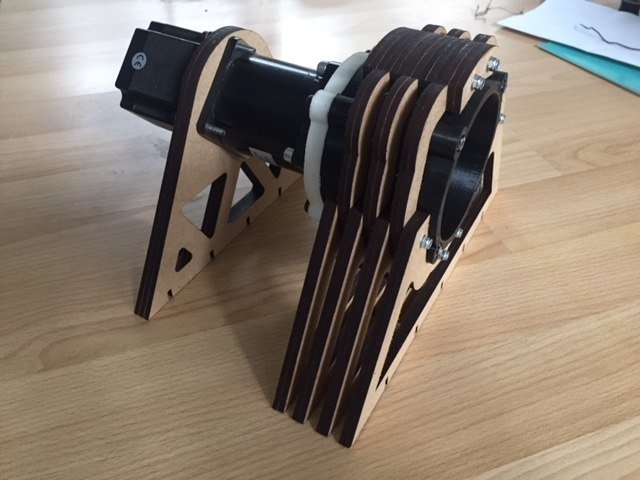
Milling
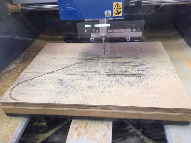
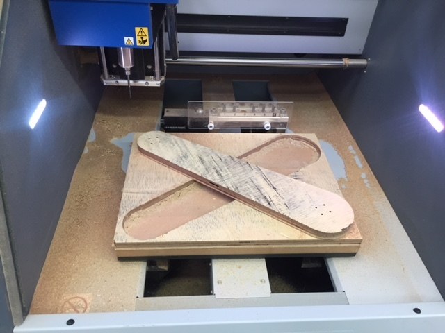
There was a grand plan to create the whole robot out of ply. I realise this is not the most structurally stable of materials, but would have looked beautiful in the end. I also considered it a good way to prototype, but it actually ended up taking a very long time on our MDX-50.
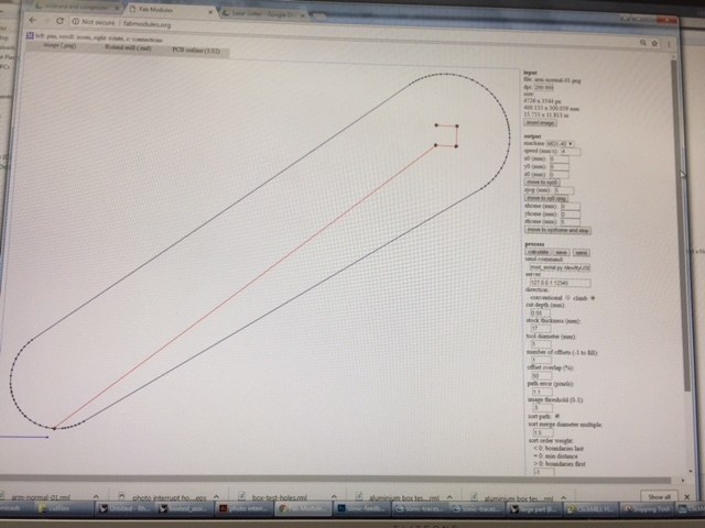
I used FabMods to create the cut files
Programming
I used Grasshopper to take the specifications of the gremoetry I was using and use inverse kinematics to describe the movement of my 2 axis.
From this I created a list of steps and directions to describe the movement of each motor.
You can see an anoted and zoomed in image of the grasshopper script below.
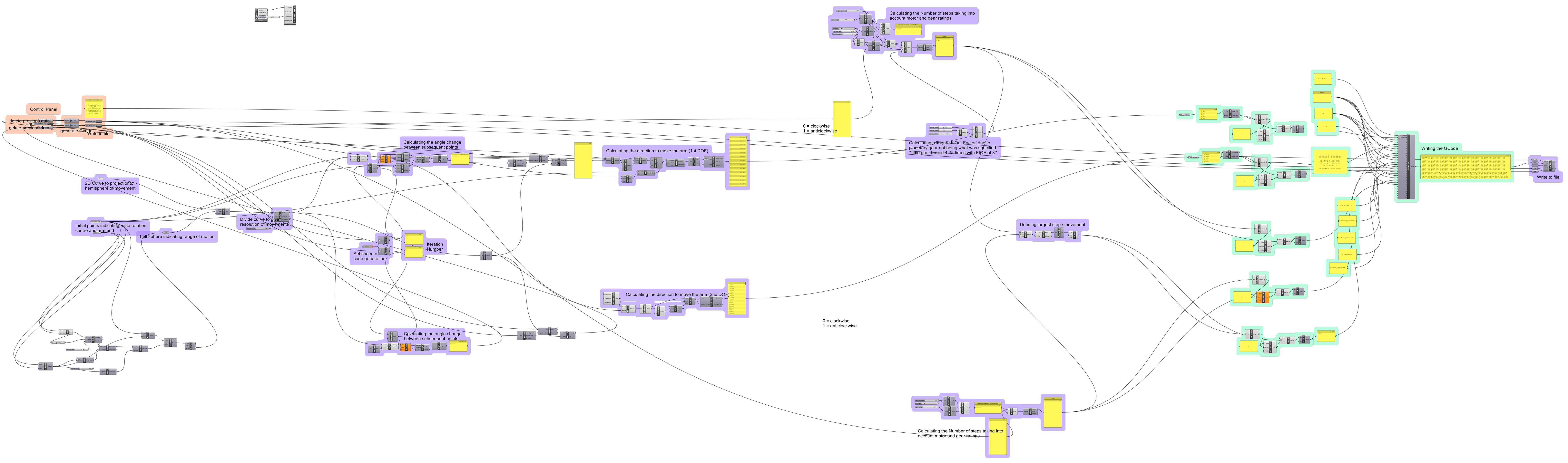
Click on image to zoom.
Bill of Materials
Electronics
To Program..