Pauduino
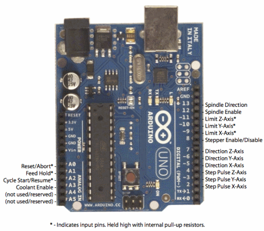
Continuing from last year I am going to try and get a working DIY Arduino. I ran into an issue last year where I could only program the board once. This led me to continue producing iterations and moving onto the next step without addressing the problem. Using Daniele Ingrasia's Satsha Kit board as a reference, I concluded that all you needed to get the computer to recognise the board as an Arduino Uno was the correct reset circuitry, the right crystal/resonator and ofcourse the circuitry for ISP/FTDI to burn the bootloader and power the board.
This is the first board I have produced. It is a simple board with just an LED to test programing the board, however I will be able to access the other pins used for programming. I created the footprint for the 328P AU from scratch in eagle, I took the dimensions of the feet from the data sheet which meant that the chip fit on perfectly. This made it very hard to place and solder so I will go back and increase the length of the feet. I was succesful in soldering using a combination of flux and wick to clean up the intitial soldering. Last year I used an 8MHz crystal, so I tried this again, but this time with a resonator. I am not sure why I did this initially, it appears the board that Satsha kit was was based on, Fabkit used an 8MHz resonator. If you search this FABkit document, a new board is added to the Arduino IDE, specifying the 8Mhz crystal. I enever did this, so I will try and change this. My other issue I also had last year; having just one pin on its own is very fragile, so I will need to fix this with some solder and glue. The big improvement I made on last year was creating easy connections for the ISP and FTDI connections. This makes it much easier and to setup and program the board, not having mistakes with connections.
The bootloader burnt absolutely fine, however I was unable to program the board. I was doing this in the standard way by clicking the 'upload' button in the Arduino IDE interface, and it gave me a message that suggested it was out of sync. However, after reviewing the Satsha kit page it looks as if I should have been using 'upload via programmer so I will try that today and also adding the 8MHz 'Pauduino'.
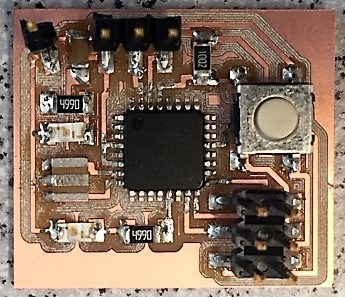
Success!
I actually hacked the Pauduino with the 16MHz chip as I tried the 'upload via programmer' option and it didn't work. I later realised I had the USBtiny cable on the wrong way round. So it worked and I managed to upload a simple 'blink' sketch muultiple times with both the 16MHz crystal and the 8MHz resonator. In the future I will stick to the 16MHz and the two capacitors as this will give me better performance.
So I am not actually sure what the issue was last year. I was able to program my boards once, but then it locked out. I was convinced this was something to do with a fuse in the chip as there was some documnetation on that. It may have also been the batch, but other colleagues managed to get their boards working. I think most likely is I was starting to far down the line with very complex boards and there was probably something wrng within my circuitry; that is my main reason for starting out with a simple blink board this time round.
With this I will try and prototype all my boards from here. As much as possible I will try and reuse components as last year I got through quite a few.
With 'Output Devices' week ever looming, I hope to make progress next on recreating the Satstepper board. With this I should be able to control NEMA 17, 23 and 36 motors and hopefully at a cheaper price than to buy the drivers complete.
Update!
During Output devices week I did manage to create a SATSTEP board. Further information can be found on the output page, but my issue was I wasnt sure how to control the board. This came from a lack of knowledge on steppers and their drivers. After Machine building I understood more about this and created a Pauduino board to control a pololu.
After some advice from Daniele Ingrasia (creator of the SATSTEP), I should have been able to control this driver and a NEMA23. Unfortunately this did not work. I hope to have time to remake the board with the knowledge of what I learnt last time in hand, but I may end up using a premade driver to drive the NEMA23 on my arm.
I have subsequnetly managed to get the NEMA23 working with the highly cost effective and effective effective TB6600 stepper motor driver. This was simple to hook up using what I had already and it could even be driven using the code I had used already with the pololu. I had to 3D print a small coupler to join the NEMA23 to its planetary gear, but I managed to get it turning.
What I have now realised is that with a 100:1 gear ratio, the arm is going to move very slowly. Looking at some Example Code it appears I can run it at least 10 times faster than I am, with a smaller time interval between step pulses (50us instead of 500). I need to experiment to see how low I can go. There is very little manufacturer documentation on this driver, but its accesable price means a lot of people use it and have written about it.
Mechanics
Based on the AR2 I started to put together a rough idea of how I hope the move the joints to work in Rhino.
This is initially a lot more difficult tha I had anticipated. There is so much to consider and calculate, but it is a bit chicken before egg. I need to figure out the weight and forces created by each part of the arm so I can size the motors and components, but I can't do that until I know the the size of the motors and components.
After research and advice from Luiz I am going to keep the weight as close to the base as possible. For this I will try and use pulleys so motors can be placed a joint before in many instances. I am also going to base intial sizings on the AR2, a very well documented open source robot arm. I have orderd some Nema motors, planetartary gears and bearings used in this design to begin playing around with.
I was advised to start at the end of my robot arm and work backwars along the degrees of freedom, this way I would be able to size the motors and planetary gears going back. I did make a start with this theory, but the end joints I am planning on making are quite complicated and maybe not the best place to start.
IMAGES OF END JOINTSAs I am basing the design and mechanisms on the AR2 I am moving back a few steps. The planetary gears I purchased were double the size than those spec'd in the AR2, this was beacause they were either the same price or a tiny bit more expensive and I figured at this stage it would be good to oversize for protoyping.
To get a better idea of the lower joints, I did a cardboard mockup of how I saw the lower joints coming together.
.jpg)
.jpg)
.jpg)
After getting an idea of how this joint will work, I began to design the bearing and motor attachments for the base of this joint. I already had the bearings and the planetary gear so i designed around their measurements.
I had an issue with my prints not starting off too well. Our instructor Luiz showed me a great trick using some tape...
.jpg)
.jpg)
Prototyping...
.jpg)
.jpg)
.jpg)
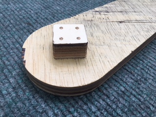
For the arm section my instructor Luiz suggested milling this out of plywood. I love the idea of a robotic arm made entirely of ply or other wood. There are potentialy some mechanical limitations which may increase the tolerance of the machine, but it would certainly be an eye catcher.
I designed an arm the biggest size I could that would fit in our Roland MDX-50, and some accompanying attachments with pilot holes for 3mm dowel to help stick the parts together.
.jpg)
.jpg)
.jpg)
.jpg)
.jpg)
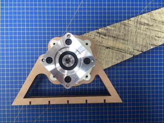
Having created this joint and the arm to go onit, it was time to create a holder, so it could affix to the degree below securely.
protoyping...
.jpg)
.jpg)
.jpg)
Success!.. So I went on to build a more detailed and stable model for the joint and to hold the NEMA23 motor and gear.

Programming
I want to control the arm using the Grasshopper interface with arduino. I have managed to create a model for inverse kinematics for a 3 degree planar robot arm, but looking at the maths for the more axis and non planar looks very complicated so still a WIP. I also need to figure out the angular momentum of each of the points to allow for smooth movement, which is a much more complicated form of mathematics called jacobian matrices.
To get the equations for this movement I used the lectrue notes on the Introduction to Robotics course run by MIT and also other documentation referencing this.
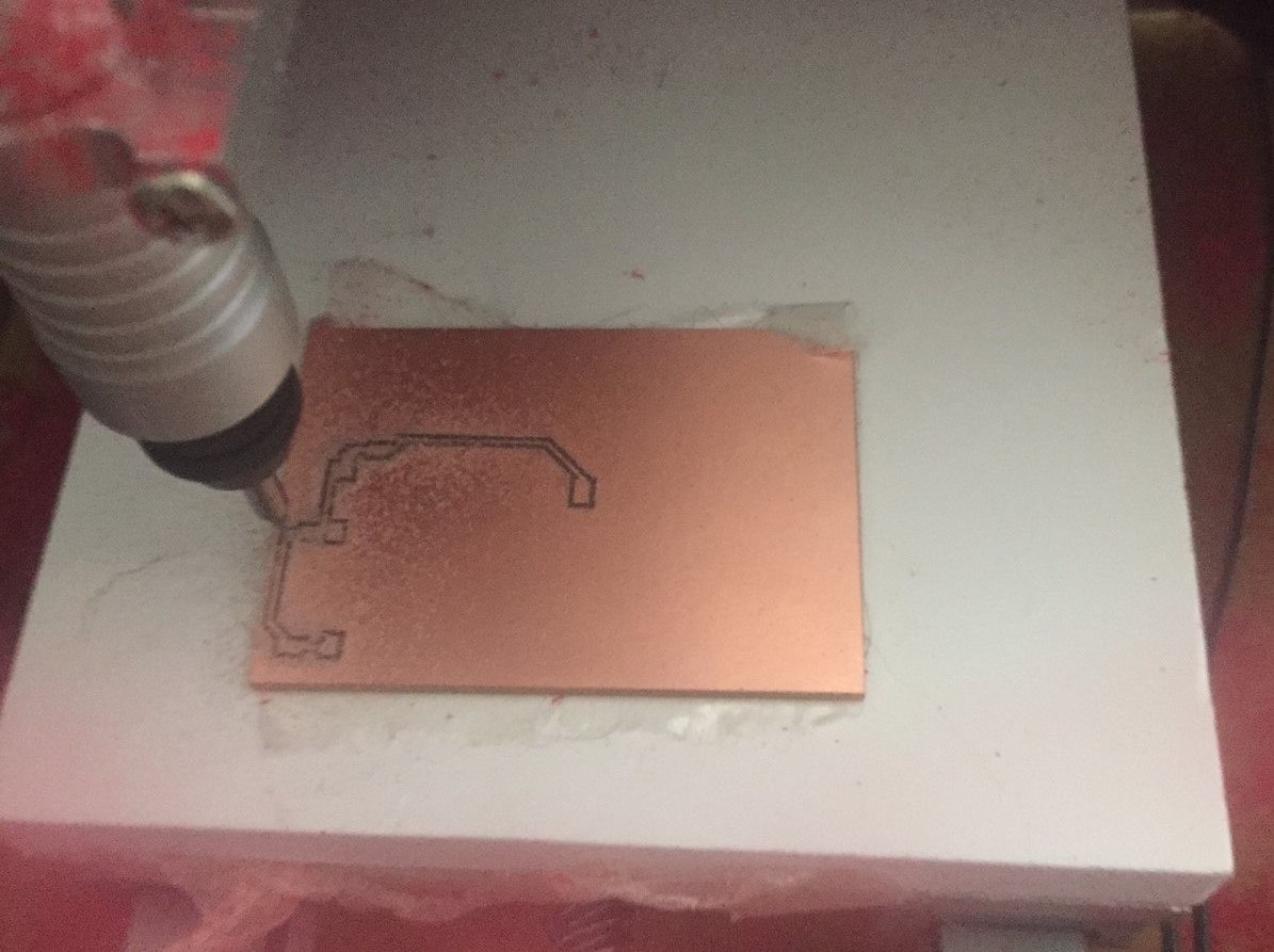
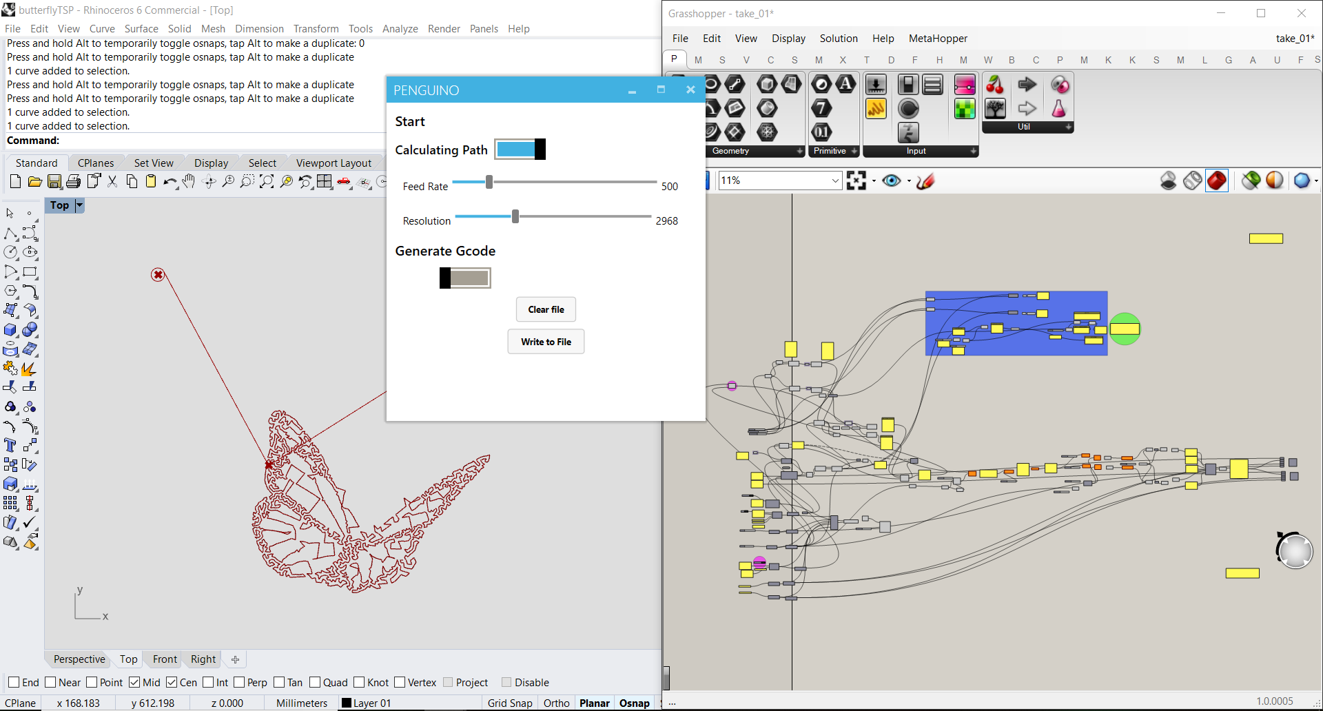
I had my first intro to gcode, which I envisage I will eventually use. I have a small mill at home called a Micromill. I didnt really like the way the code was produced and it messed up the scale of the board .png I produced (it recommendea site called Easel by Invetables). Using the grasshopper script I used to turn the eagle exported .dxf into a file for the vinyl cutter, I developed further a script that would take these traces and turn it into gcode. My initial experiments appear to be succesful, however I believe I have a problem with the Z access on the machine and it is hard to get it to the right height and to stay there.
It turned out I did have a problem with the Z, I was missing a small spacer which stopped the play I was having in the Z axis. After promptly receiving replacements I could have my first real test with the G code and milling the boards.
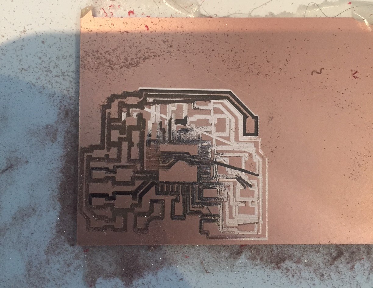
My first proper attempt showed me 2 things.
To remedy this I first created file for levelling...
I then set to work on my gcode and found it was when offsetted toolpaths became open curves, my logic for creating the code did not work as well. a quick tweak and another test tonight.
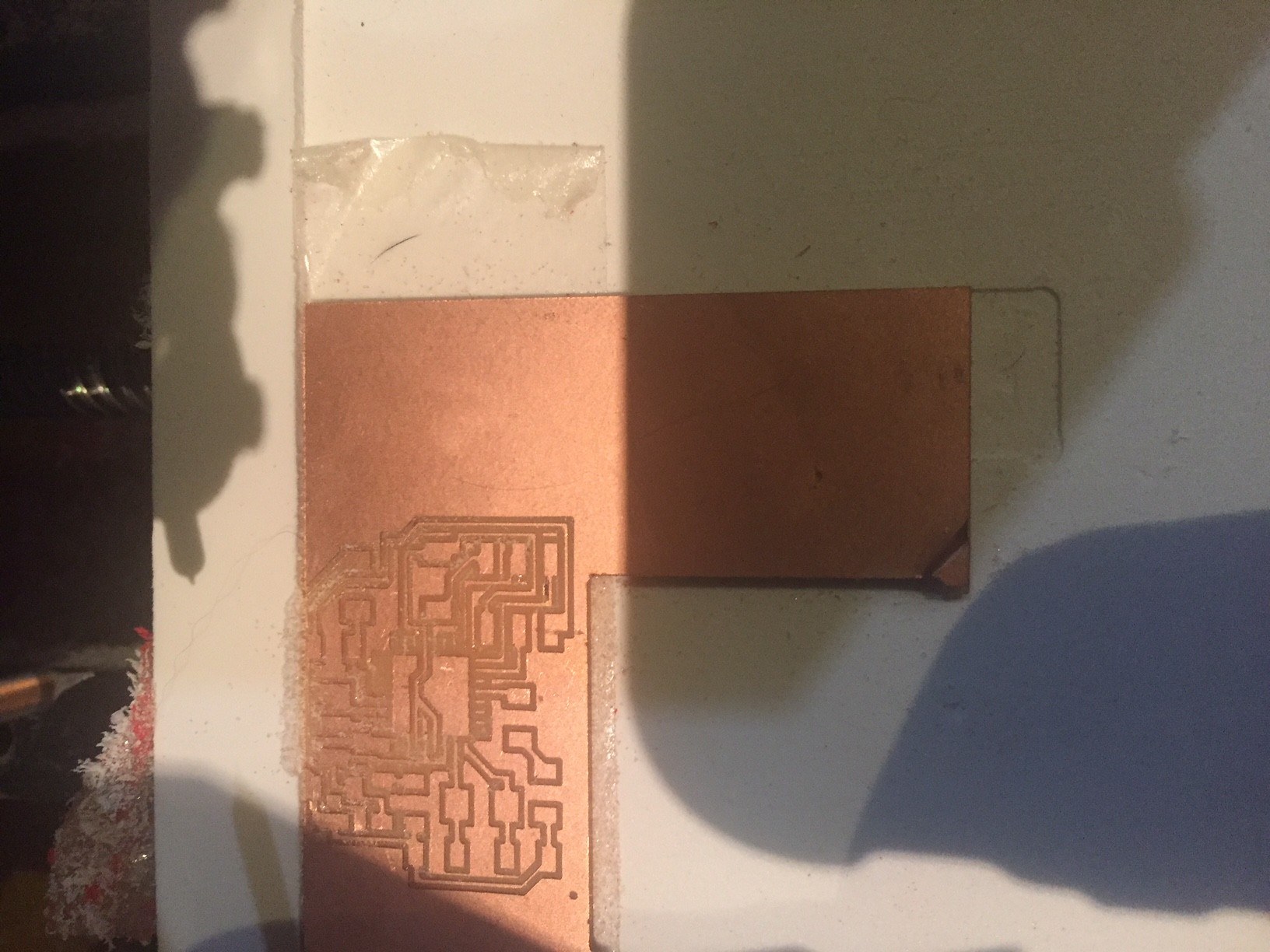
SUCCESS!
After contacting the manufacturer, it turns out I was missing a space for the spindle. After receiving it, I had much better results. I had a bit of an issue as I seem to have tool bits that fit between the collet sizes I had, but after sufficient tightening my z-axis issues were fixed.
Also having tweaked my code a bit I was finally getting a decent mill. I think this machine is designed for much less precise work (assuming my code is working as it should) beacuse some of the trace widths were very variable. So far I have just been using the 0.4mm bits, but I might try with 0.1mm and see what I get.
Programming continued..
During the Machine Building week I spent time to create the gcode for our machine Using Grasshopper. This was very succesful, using inverse kinematics to create a file that I could upload directly to my RAMPS board (Using marlin firmware).
The first task for this was to understand the geometry and variables of the machine, then to calculate the cable length with the gondola at a certain point.
To do this I used the Marginally Clever website.
Once our machine geometry could be read and any point along the curve it was a case of reading the values at subsequent points and finding the difference from the previous value. Once I had the difference between each point on a curve, I cumulatively added these so I could use absolute coordinates on my machine and add the relevant ‘G’, ‘X’, ‘Y’, ‘F’ value.
I had a play with using the HumanUI plugin for grasshopper. This allows us to create a more user friendly interface to control the generation of gcode. The 'spaghetti jusntion' of wires can sometimes be intimidating to those not familiar with grasshopper.
During Output devices week I controlled an Arduino using just Arduino code - no libraries, no gcode reader. I can see Daniele Ingrasia has used GRBL Gcode reader on his board, so it may be possible to upload this to my Pauduino, alternitavely I can try to create arduino code from Grasshopper.
My micromill did use the GRBL code, and it certainly is not difficult, however I worry about interfacing this with my Hardware.