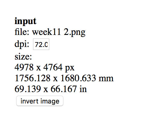
Note: you will see on the top right hand side of the screen now that there is a bit in bold titled "input" which contains information about the file you've uploaded. Double check that the size listed is correct and that the dpi is also correct.
This week has been the most easy and yet difficult thus far. Understanding milling has been weird for me. It has both been easy and difficult to follow and understand. I am trying to get more accustomed to terms used and remembering what they mean. For example earlier this week I though "fabmodules" was a file type or a document, just to remember moments later that it is the website Neil created.
On Wednesday after the class, we were shown how to use the machine. It was a lot to take in as I've never even seen one before prior to being in the lab. It is fascinating that we can make our our boards here in the lab. I was worried I would need to invest in an arduino board for my final project so it is nice to know I can save myself some cash and tailor it to do exactly what I want it to do instead of potentially buying a board and only needing a fragment of it's capabilities.
How-To: MDX-50 CNC Milling Machine - Setup
Setting up your board:
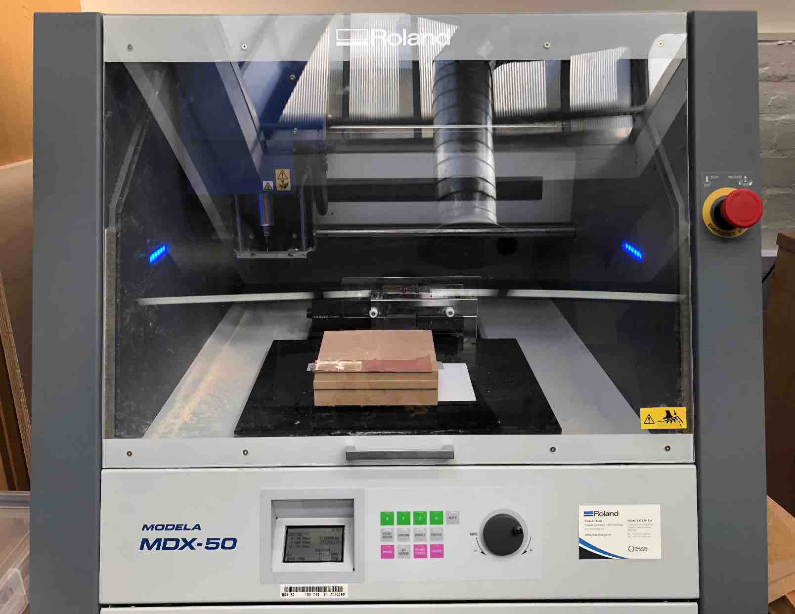
Setting up the machine:
Editing the board:
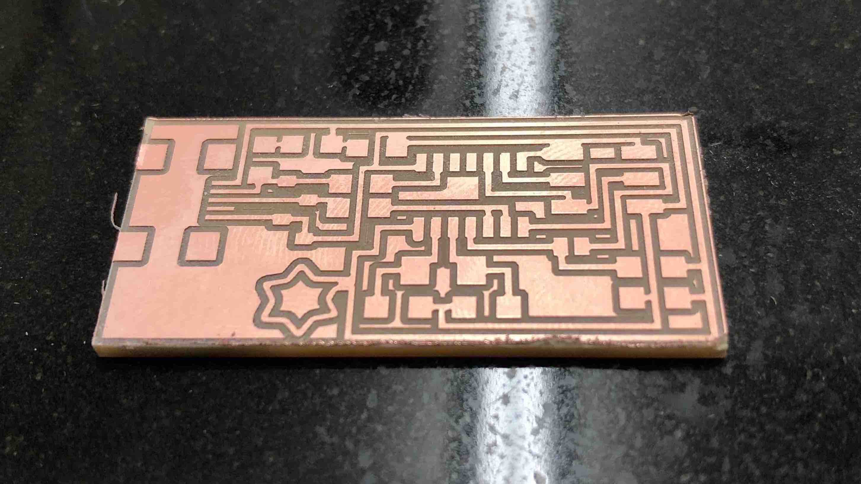
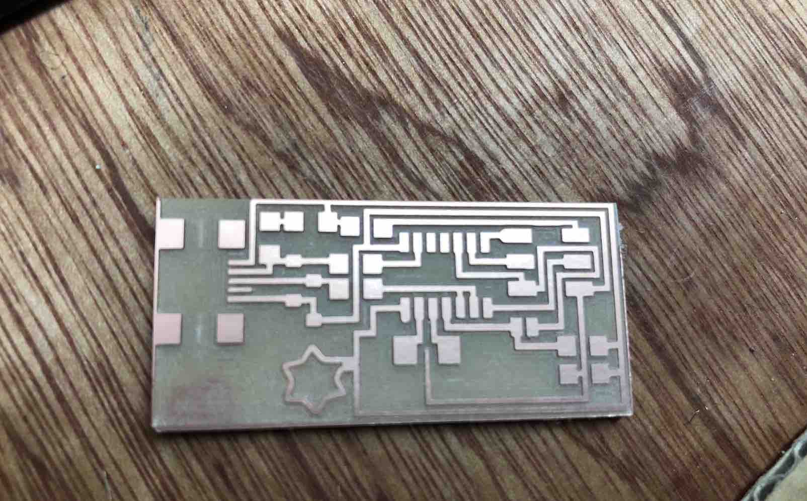
Making the board was a lot of fun. Everyone was adding their own touch to theirs by adding a logo. Initally I had no idea what to do as my logo and through sheer lack of creativity decided to go with the start theme again. However after creating it and seeing it, I think I might use a star as my logo for the fab lab. Perhaps design one to put on this website as well.
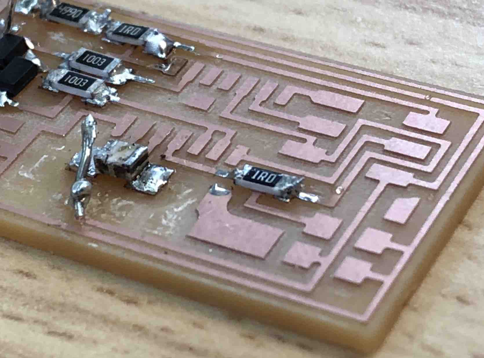
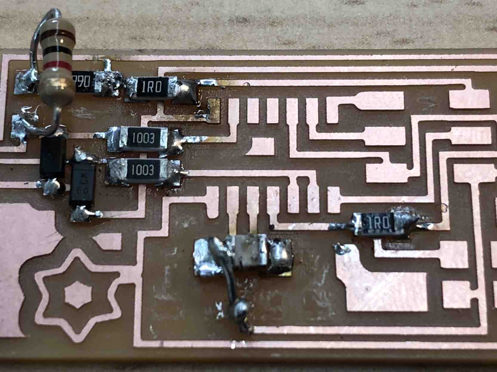
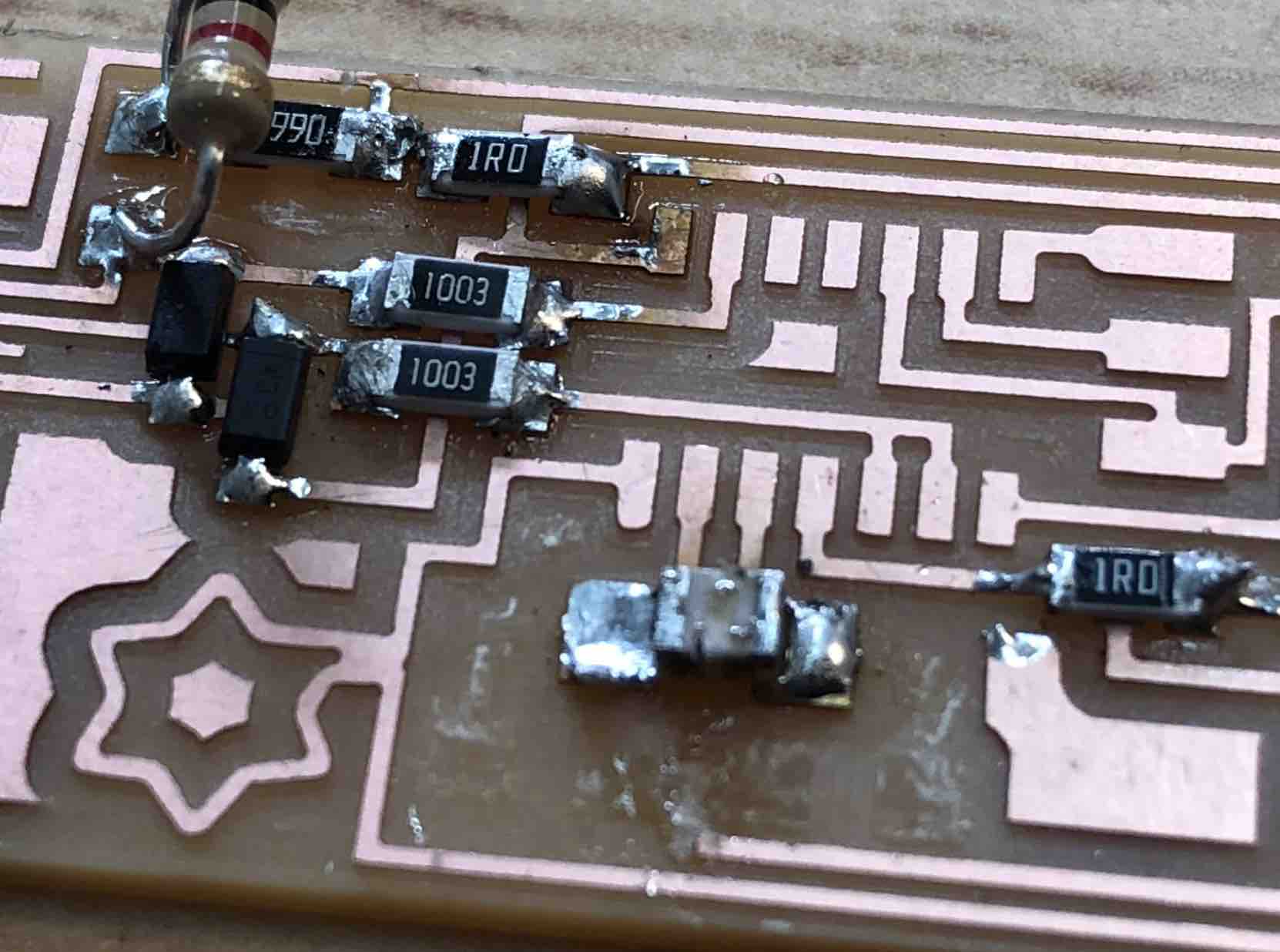
Unfortunetly, some of the bits did not come out as planned, and in the process of trying to manually fix it, it ended up being broken. However! Luiz and I managed to fix it using DIY methods.
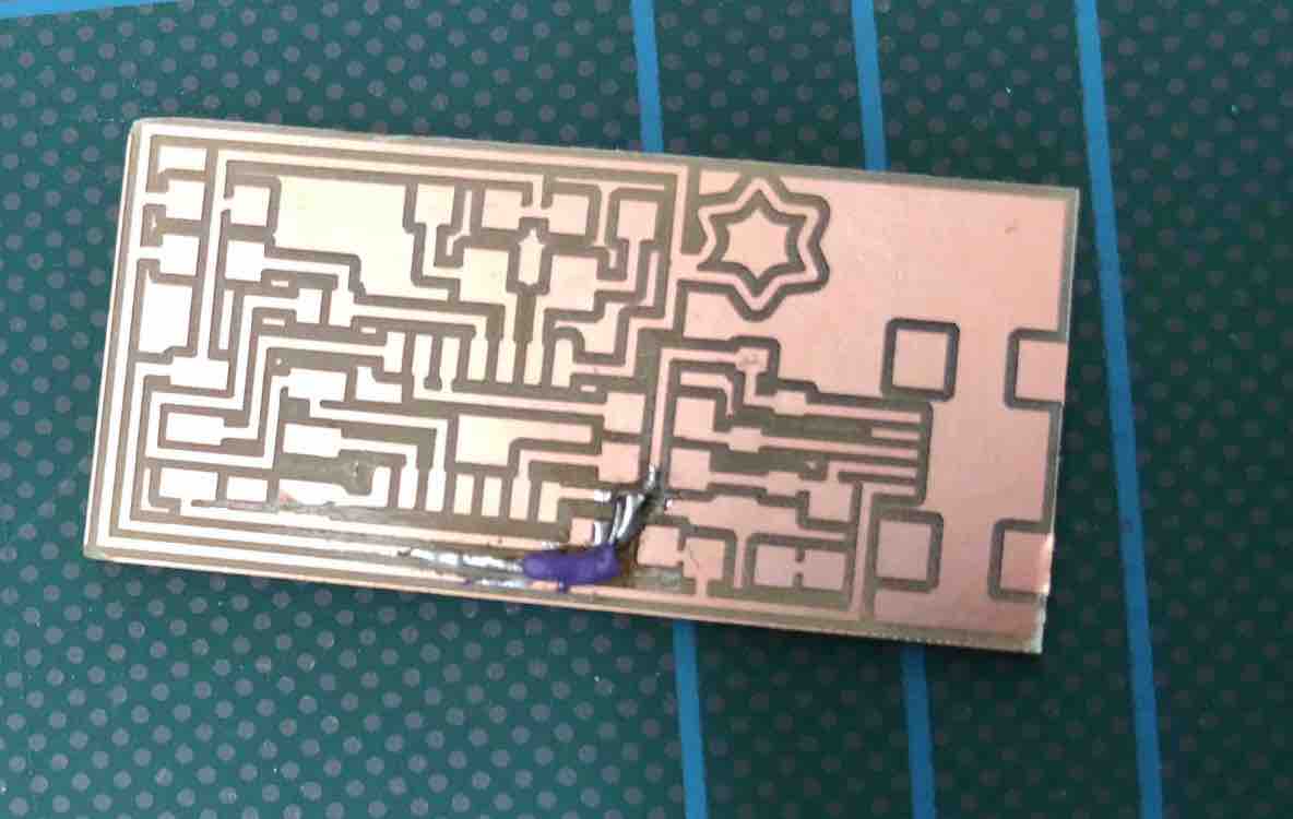
I still however wanted to create a new one, but it's nice to know that all is not lost if it doesn't turn out perfectly. It also gave me a chance to adjust my star's placement as I felt it was too close to the lines and I wanted there to be some distance.
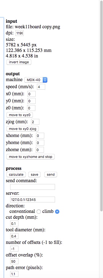
How-To: MDX-50 CNC Milling Machine - Setting up the Board to be Milled
Note: you will see on the top right hand side of the screen now that there is a bit in bold titled "input" which contains information about the file you've uploaded. Double check that the size listed is correct and that the dpi is also correct.
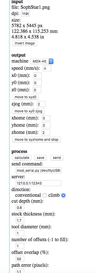
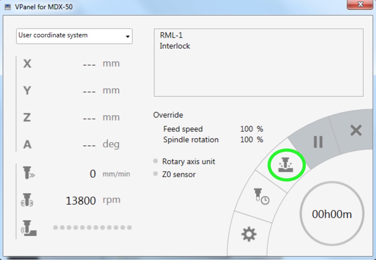
How-To: MDX-50 CNC Milling Machine - Milling the Board
Note:Make sure the XYZ are the same as the machine!
Note: To be double safe that nothing else but your own board gets milled, hit delete all before uploading your .png
Note: Keep an eye on your milling board, this way yo can ensure nothing is going wrong or you accidentally seemed to have missed a step along the way. If a problem exists, you can pause it from VPanel. If it is an emergency, hit the red button on the side of the MDX-50 machine.
Tip: The "override" button can be used to alter the speed of the machine during the process.
Note: Again, keep an eye on things happening. It should only take a moment anyways to mill
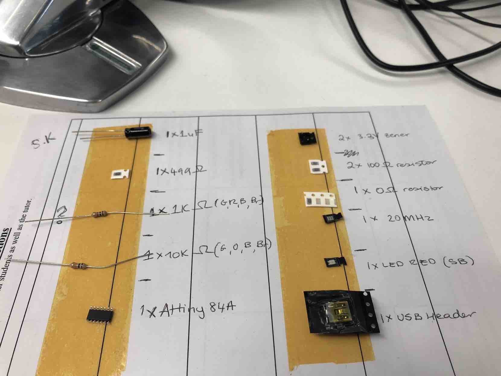
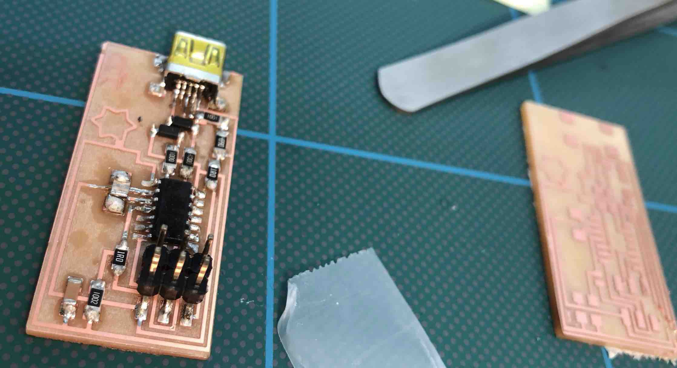
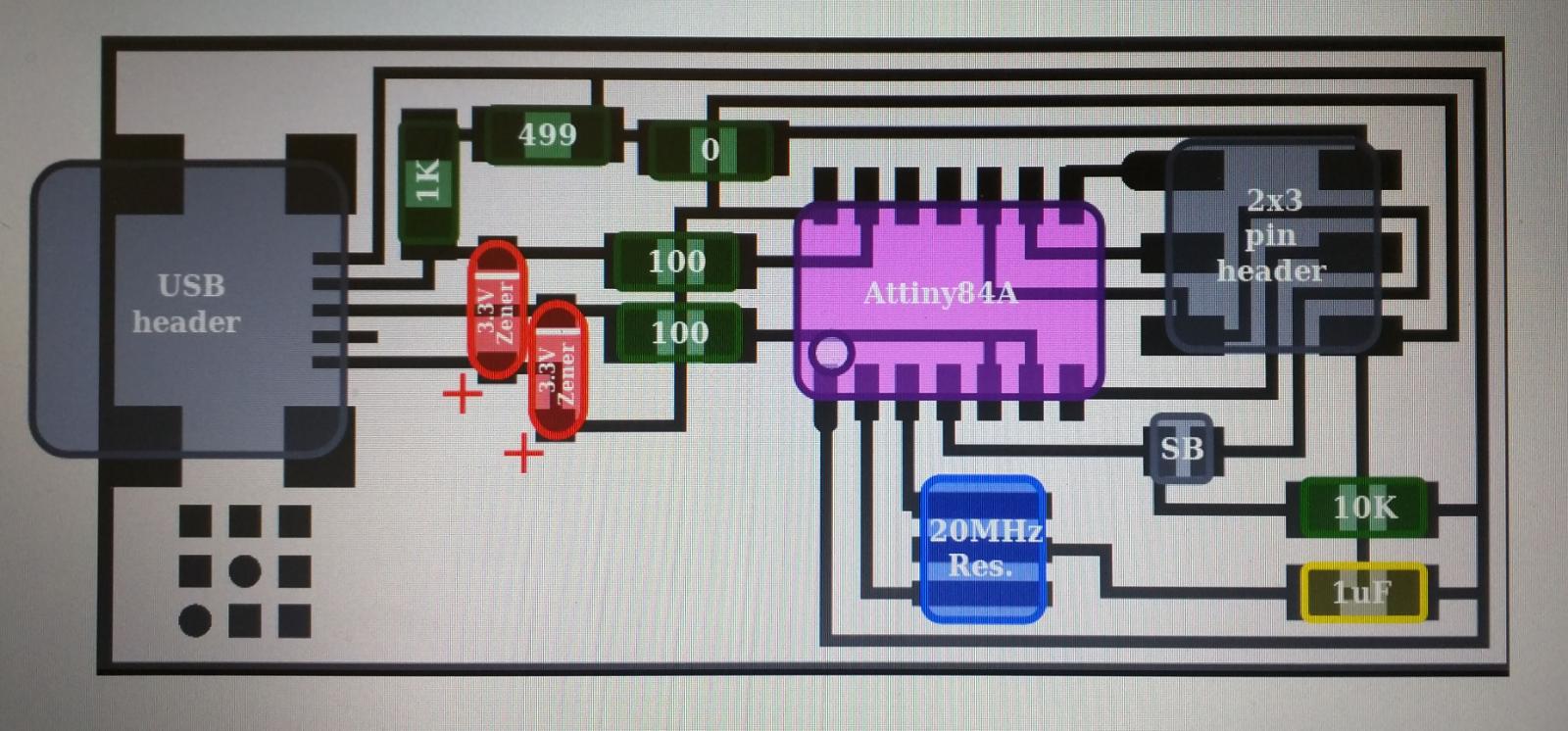
I re-did my board on Monday and began soldering my parts on. I used the template to guide myself and stuck my bits on double sided tape stuck to paper that I labelled to avoid confusion and speed up my soldering and be more efficient.
I didn't finish, but managed to do most of it. The remaining parts are the bigger bits (the resistors and (SAY WHAT ELSE BASED ON LIST). However, when I returned Wednesday to continue, I ended up breaking my board and so need to make a new one again.
It is frustrating but at least now I will be able to create one that avoids the issue I had before.(ADD IMAGE OF NEW DESIGN OF BOARD VS OLD DESIGN TO SEE DIFFERENCE)
On Thursday (22nd) I re-attempted my board for the 3rd time. The first failure was that the zero sense didn't work and so my board wasn't cuting through properly. So I restarted and set my z co-oridinate manually. It all worked smoothly and it looked more visually appealing... that is until I did the outline bit to cut my board out. Everything was working well nutil the last second, when the machine was returning to it's finishing position, it cut through some of the board.
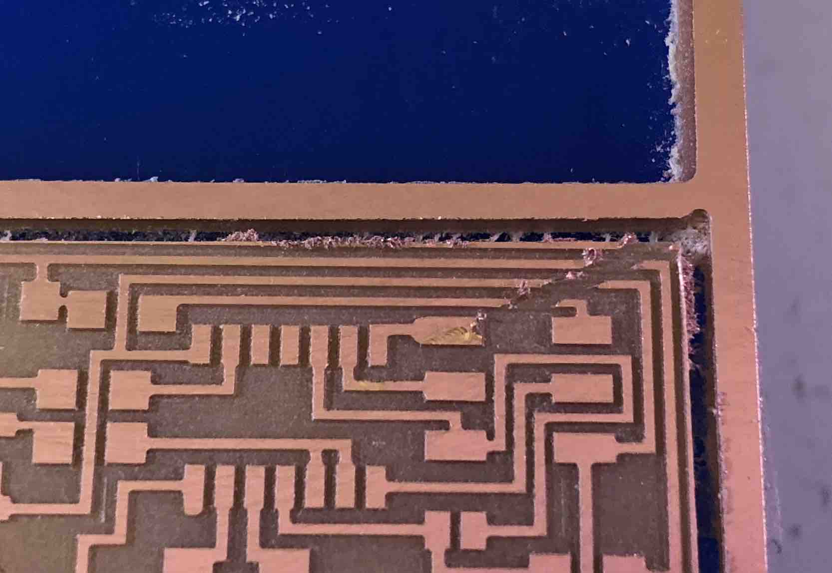
This meant having to re-do my board fot the 4th time! Very frustrating and was very de-motivating. It can be fixed, but as the point it cut through is so small, I'd be spending more time trying to fix it rather than if I simply made a new board. After he fourth attempt it finally worked!
Howver, as it was a very long day, I didn't start soldering till Monday that follwowing week. I did manage to solder everything on Monday, ran into a few bumps though; when I was soldering my USB bit, I accidentally soldered a bit together and had spent ages trying to remove the solder which was so small but obviously didn't work (confirmed through continuity testing the board).
Despite the fact that it took 4 attempts to finally mill my board and then solder it all correctly, the siverlining to it meant I got to do lots of re-milling and re-soldering so in a sense I got much better at doing the two. And having the offset, something I hadn't done in my first board, meant it looked cleaner.
How-To: Soldering the board (Tips and Tricks)
Just when I thought the worst was over, the next storm came in...
This is the link thatacted as our guideline to program our boards
http://archive.fabacademy.org/archives/2016/doc/programming_FabISP.htmlFor whatever reason, still unbeknowst to myself and Luiz, my programmer refused to a programmer! I've tried once more to mill another board and solder it, but still, nothing. It wasn't until take x (I lost track of how many attempts there were at this, yes there were THAT many), where I decided before giving up and cutting Luiz's board to see if maybe the problem was with my design, to try programming using his programmer but instead now from my computer that it mysteriously worked. On the first time too. Not sure why. The only difference made was switching devices. But alas it worked.
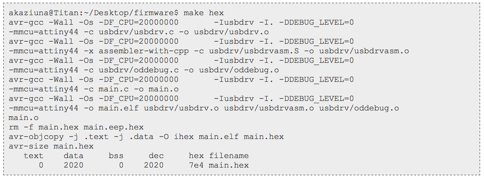
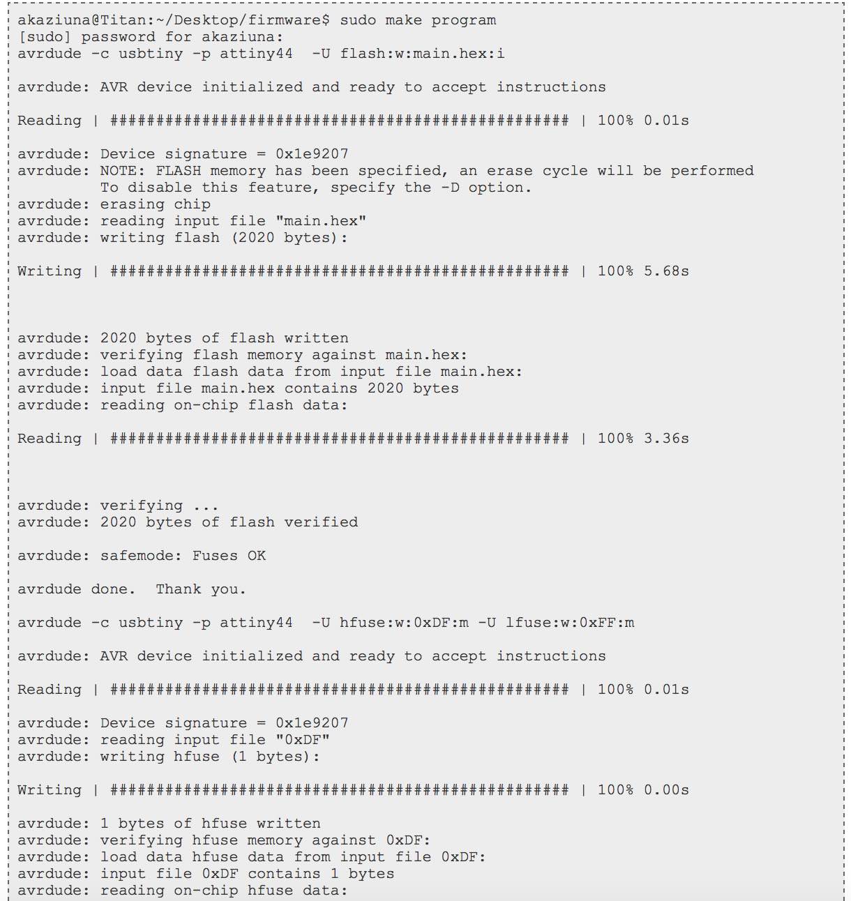
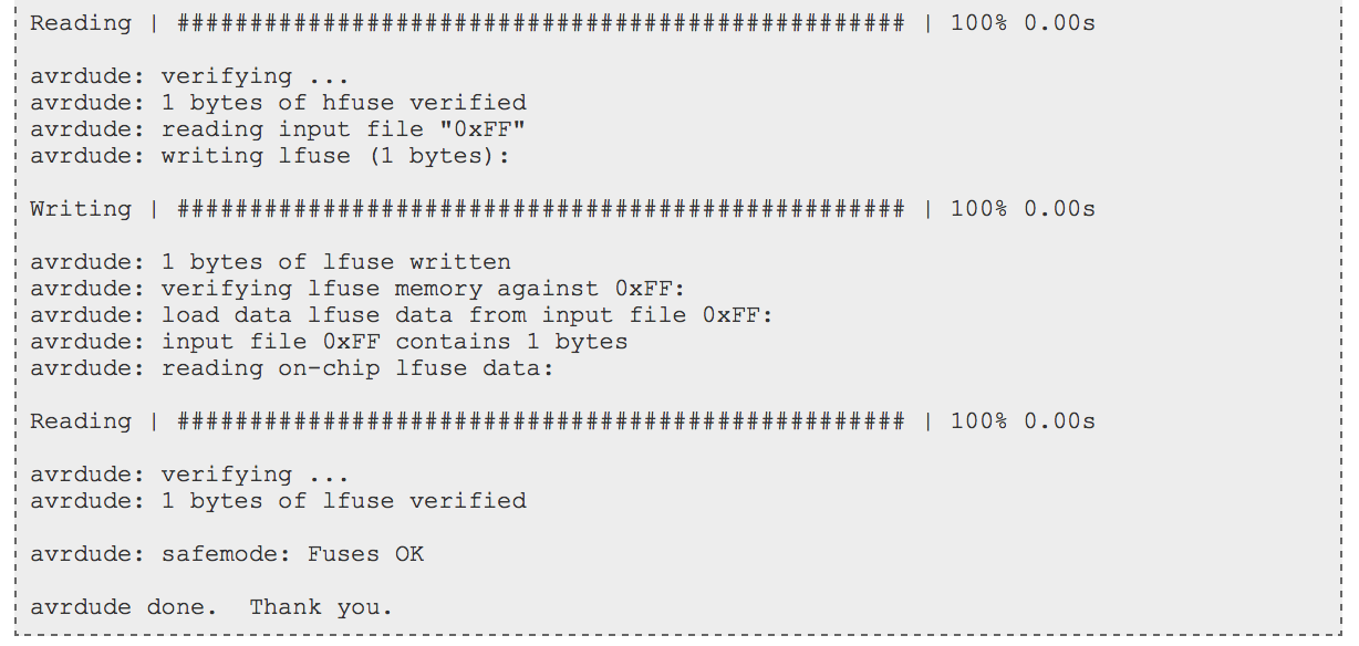
Initially we thought the issue was with the feedback given by the board during the prgramming stages (see below image).
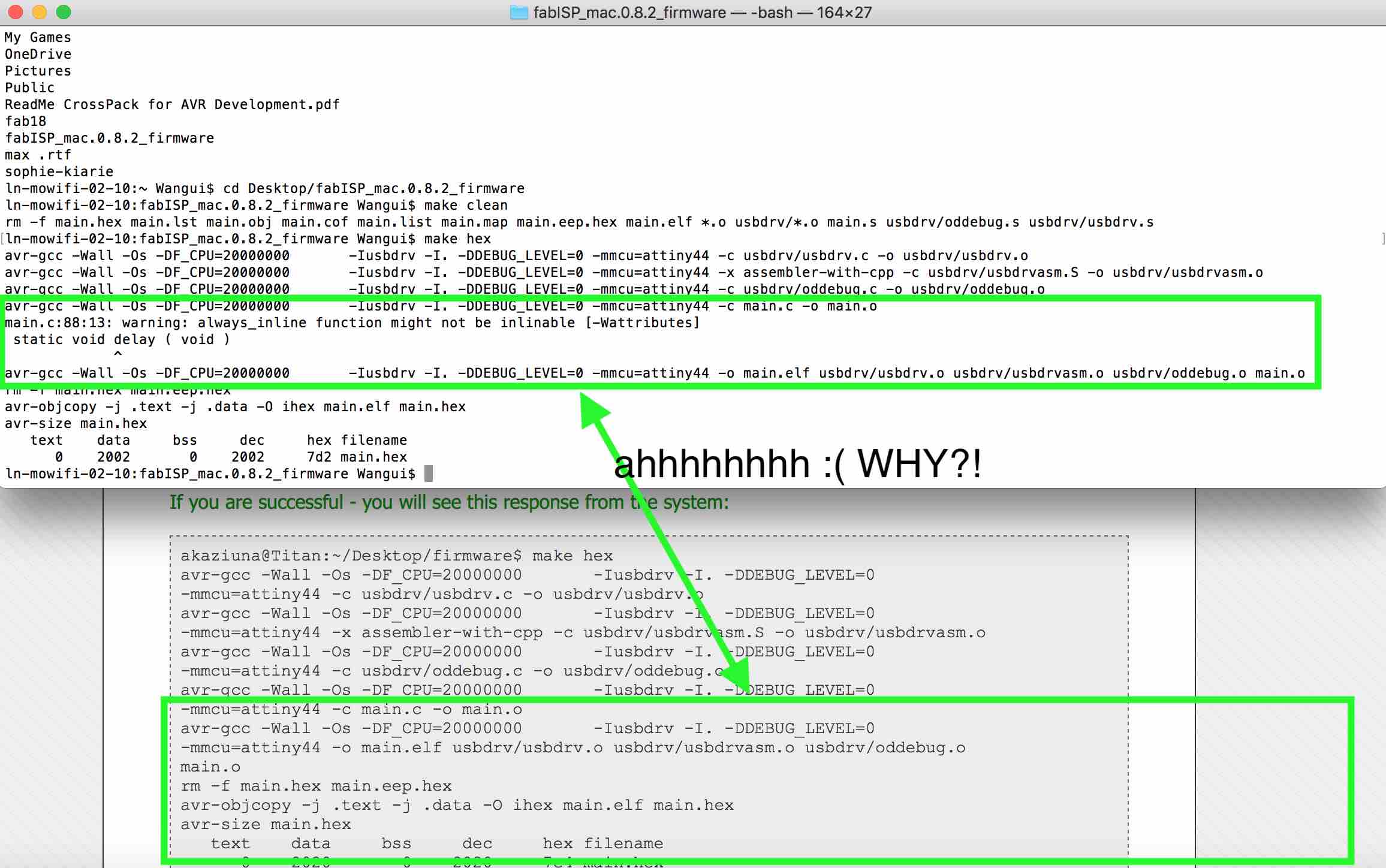
But when the same message appeared on my screen when I was trying it from my laptop, it still worked. Which is puzzling as it does not appear in the document posted on the fab academy site....Unfortunetly it was too far down along the line to bring it up with Neil (in terms of how many weeks had passed since this week).
On the fab link, it states things to look out for if the board doesn't program (see image below)
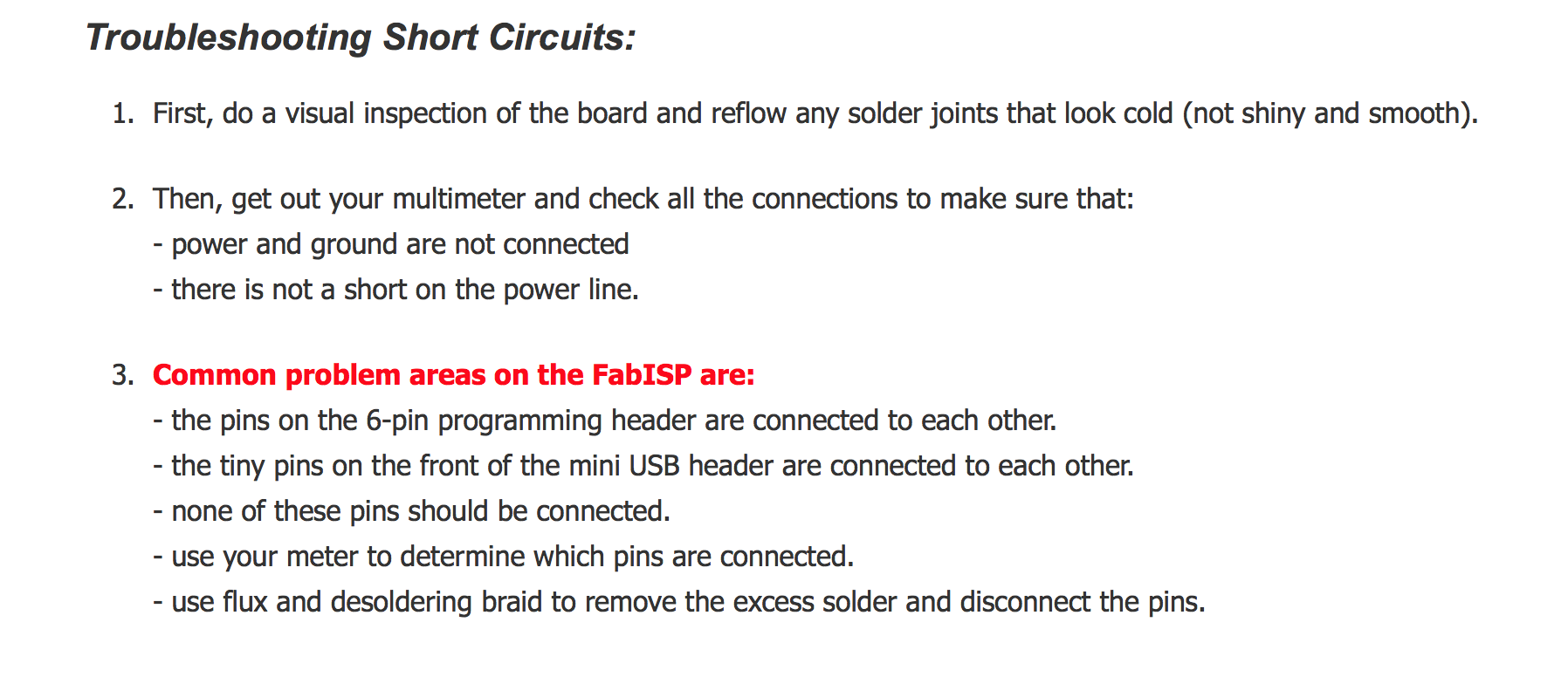
However, when I double checked everything, including checking all the soldered component parts under a microscope, everything was alright. At least I can say that out of this, my soldering skills are basically amazing if I do say so myself. ;)
How-To: Programming the board Part 1
Because I had issues with mine, for documentation purposes for the instructions, I will be using images from the fabacademy instructions page..
#AVRDUDE = avrdude -c usbtiny -p $(DEVICE) # edit this line for your programmer
AVRDUDE = avrdude -c avrisp2 -P usb -p $(DEVICE) # edit this line for your programmer
If you are using the USBtiny programmer or another FabISP....:

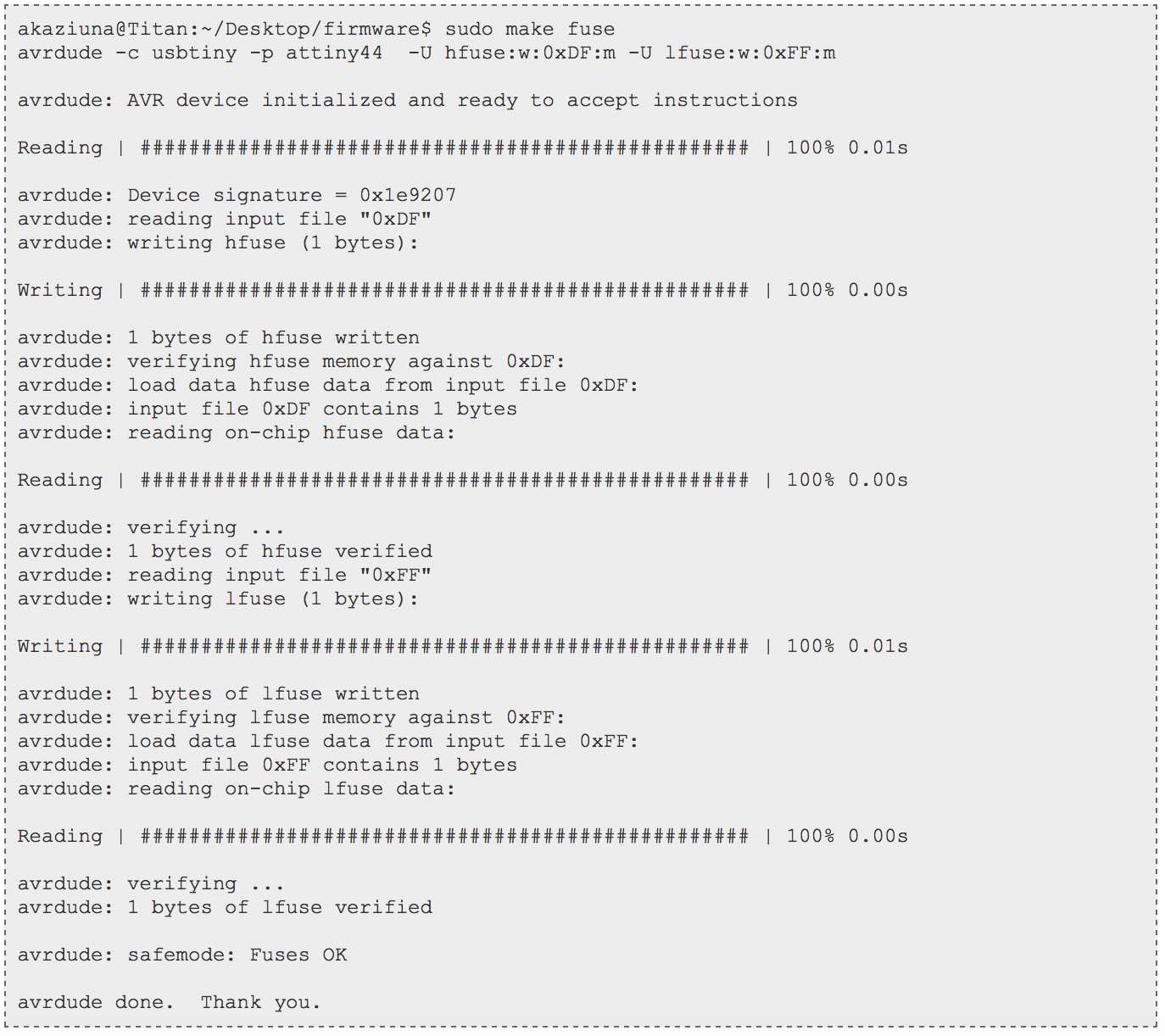
How-To: Programming the board Part 2 (Programing the board to be an ISP)
Is my programmer a programmer now?!?
The answer is hopefully yes. But to double check, go to the "apple" menu in the mail toolbar and select "about this mac". From here select "system report", and under the "hardware" - go to "USB". Here you should be able to check to see if your ISP pops up. If not, go back and try to see what might have gone wrong.
Once you have confirmed it is, remove the 0 Ohm resistor on your board as well and the solder bridge. AND HEY! LOOK AT YOU! YOU'RE COMPLETE!
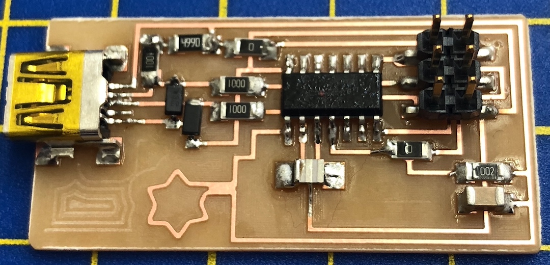
My Programmer
Luiz's Programmer
This weeks homework:
And for those extra brownie points...