

Week 11
Input Devices
Individual Assignment:
Measure something add a sensor to a Micro-controller board that you have designed and read it
Group Assignment:
Measure the Analog levels and digital signals in an input device
My contribution is in group work is to do documentation and understanding oscilloscope
key learning from this week
1 Using ldr senor and understand its connection and programming
2 Making board which have multiple features as on board sensor , pins for external sensor , 12v power socket and proposal for motor connection etc.
Files
1 Eagle Schematic and Board file
Designing board for Input and Output week
As i got basic understanding of designing in eagle so i tried to make circuit which have multiple things in it and the process i understand for designing any board
1 Define your requirement
2 Select and make list of component why you used them
3 Select micro-controller board as per your requirement and read its data sheet
4 Select those component from eagle library and make schematic and check erc
5 Specify the design characteristics i.e clearance , line width and create board from schematic
6 Do auto routing and check fab drc and do correction
7 Export your final design for milling as png file
Requirement
In this week i want to design a board
1 Which have sensor connected to it on board
2 It have option for connecting external sensor to it
3 I want to use motor in my final project so i decided to give position for motor connection
4 Give 12v power supply jack so i can directly power my motor using 12 v power source
As i am making one board for both input and output week so i listed all component which i am using in my board
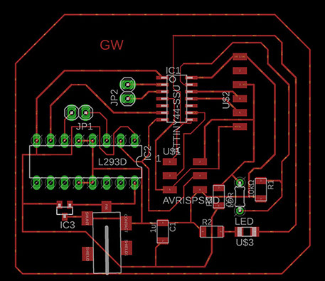
1 AT-tiny 44 - As At-tiny 44 have more i/o pins than AT-tiny 45 and the PCB i am making i need 5 i/o pins also i tried At-tiny 45 previous week so i tried this iC in this week
2 LDR sensor- ldr sensor is light detecting sensor ,i want when someone put hand over sensor it will glow led as i need to test its functionality
3 10k ohm resistor i connected this with ldr sensor
4 Red led - to check the sensor is working or not
5 1k ohm resistor - this i connect with the red led
6 6 pin headers - i used two 6 pin header one 6 pin ftdi header and another is 6 pin isp header , i used ftdi here as i need rx and tx pin for serial communication and isp header for programming
7 LDO-5.5 v i used as a voltage regulator in circuit
8 2 pin header - i used two 2 pin header one for connecting external sensor and another for connection for motors
9 L293D- motor driving ic as i need to drive motor using same board so i used this ic for controlling dc motor , we can control 2 dc motor with one ic
10 12 v dc jack - i have used this jack as in next week i am going to use this for powering my board with external power
List of component
Micro controller
I use attiny 44 in this for which i need to refer its data sheet in this the thing which is of more importance in this pin diagram of ic as which pin is for what purpose and at what pins you can connect your input, output and the second thing is about your specific need i.e you may look for temperature , memory etc.
Input devices
In computing, an input device is a piece of hardware equipment used to provide data and control signals to an information processing system such as micro-controller
Sensor i used
it is analog sensor that means it give certain value for change in light intensity for more reading refer
Some source for ldr sensor projects
some source for ldr sensor projects
1 http://archive.fabacademy.org/archives/2017/fablabuae/students/164/w13.html
2 http://archive.fabacademy.org/2017/fablabbahrain/students/999/week10/week10.html
Designing schematic of board
making schematic is easy if you know what component you are using and where to connect them for this read data sheet as you just need to import component and connect them, i use maximum of component from fab library
Error in schematic
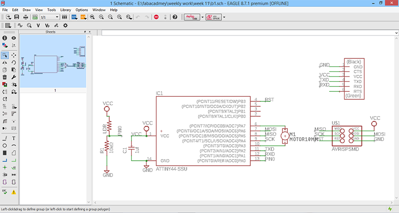
AS i started by selecting component from component library and start connecting them ,this is the first schematic i made i did lots of error which are as follow
1 in this i forgot to connect few pins as reset pin for ftdi,
2 as i want to use 12 v motor and i connected directly which is wrong
this is also incomplete schematic so i took help of research assistant in our lab for making new schematic
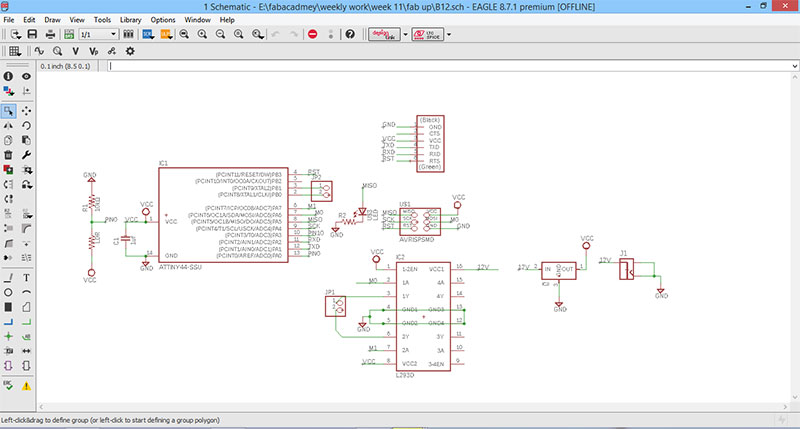
Correction in schematic
in this schematic the changes i made '
1 i add one led so i can easily check working of my LDR sensor on board
2 i add 2 extra pins in which i can connect external sensor
3 i add 12v dc jack and lm117 ic so i can use that 12 v supply to run motor
4 i have removed motor from board and i use 2 pin header for that and use L293d motor driver ic for that
5 connect all pins and check connection
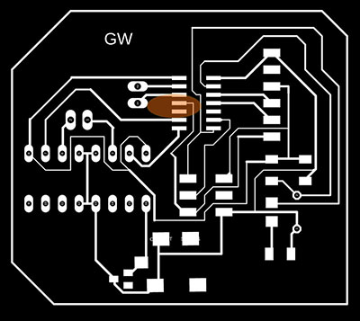
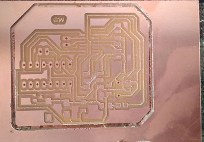
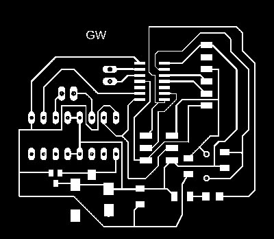
Final Board Schematic
Making Board
making board is really challenging as i add lots of thing in my board and it is really difficult to arrange component in board view without overlapping and i find lot of difficulty in this process and spend my 3-4 days in board designing only as earlier i was using net lines for joining component and this take lot of time , thanks to chandani last year fabacadmy student , she told me to help me lot me use autoroughting tool , i get 100% resolved trackes and i finally made my board
1 place component in such a way that there will be very less intersecting lines
2 keep minimum distance between two lines otherwise your path will be overlap once you done milling
3 check your png file in fabmodules.org first before taking it to milling so it save your time
Errors and Correction
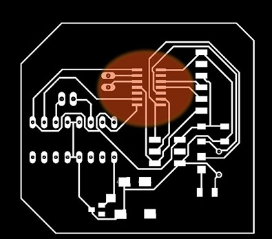
Board 1
in this board my lines are very close and they are merging on milling so make sure you don't have such lines in your board
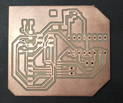
Board 2
in board 2 i solved the error in board 1 by selecting small track and rearranging the lines but again i did error i did in board 2 is that i disconnect the miso pin so at the time of programming i need to connect this with jumper but i redesign new board for removing this error
key tips - always check your schematic and board first before going further to milling and soldering as i skip this step and i need to redesign my board again just because of this ,i redesigned my board with zero error milling new board and soldering new board while soldering my tracks are broken so i remill the board for correction and d
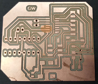
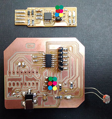
Final board
Milling The Final Board
I used same process of milling board which i explained in week 7 but this time i keep different setting for milling , tracing and drilling images of final board for making this files so i am here writing only those parameters
process is first run tracing path than drilling path than your cutting path
Refer tutorial i made on how to make trace , cutting and drilling file for milling using krita
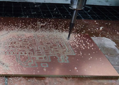
Trace board settings using MDX-20 Modela machine
1 Bit -1/64 inch
2 Speed -3
3 Cut depth -0.18-2.0
It may varies with board thickness you first try with lower value than move to higher value if that wasn't work
error -0
keep other parameters same
For cut board setting
1 Bit- 1/16 inch
2 Speed -4
3 Cut depth -0.4
4 Error -1.1
keep other setting same

Drill setting
Bit - 1/16
Cut depth -0.5
Error -0
keep other setting same

This all error come into notice when i milled my board so for removing this error i need to still again mill my board and i redesigned the board the board file by removing this error milling the board and soldering is still remaining and i will finally complete my board by this week
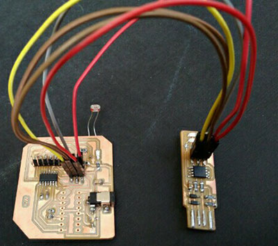
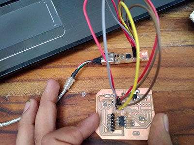
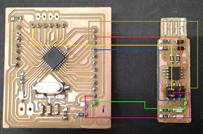
Connecting fabisp with board for programming
For Programming the board i have used both fabisp and arduino board ,the connection in both you have to connect the corresponding miso to miso , vcc-vcc , gnd-gnd, mosi-mosi , reset to reset
Note
It is recommended connect your fabisp with computer using usb to usb cable , sometime connecting direct isp to usb damage laptop port if something is short circuit in isp
Programming Steps
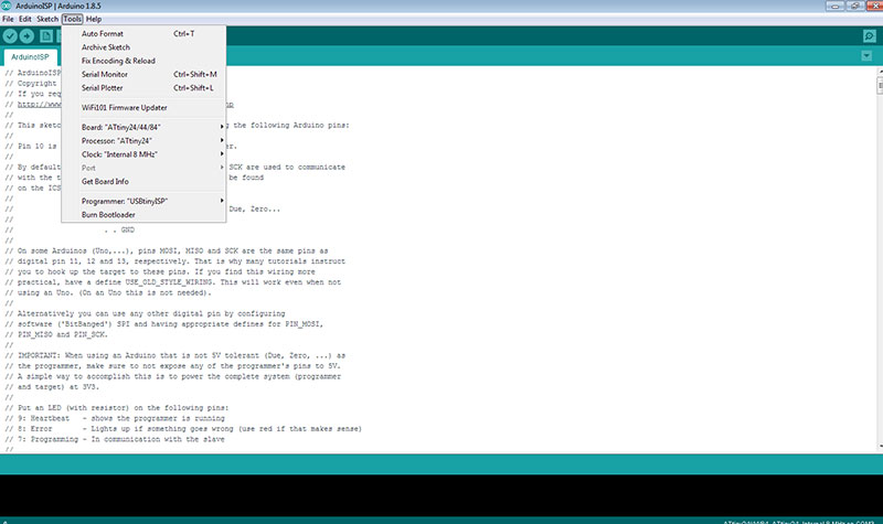
Step 1
Burn Boot Loader -we did this step for Steps when we need to make our micro-controller programmable this is the first thing which you need to do this for first one time before programming
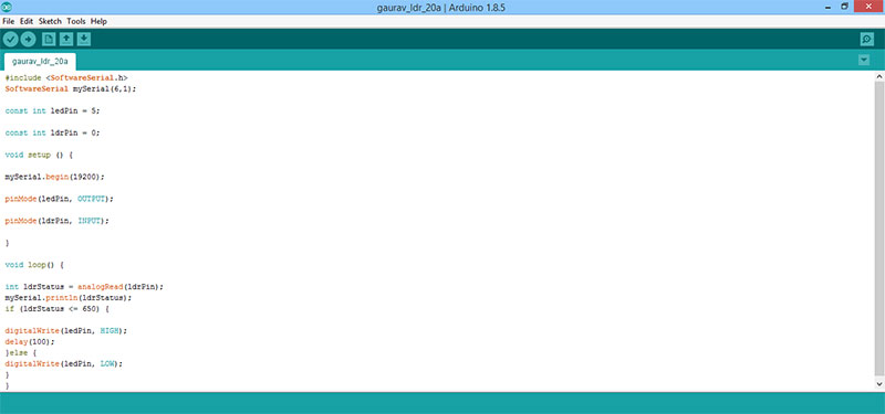
Step 2 Write Program Code
we need to read value of ldr on serial monitor for which we assign the pin 6 and pin 1 to rx and tx correspondingly and connected this pin to the rx and tx pin of ftdi cable at serial port
Testing ldr sensor on serial monitor
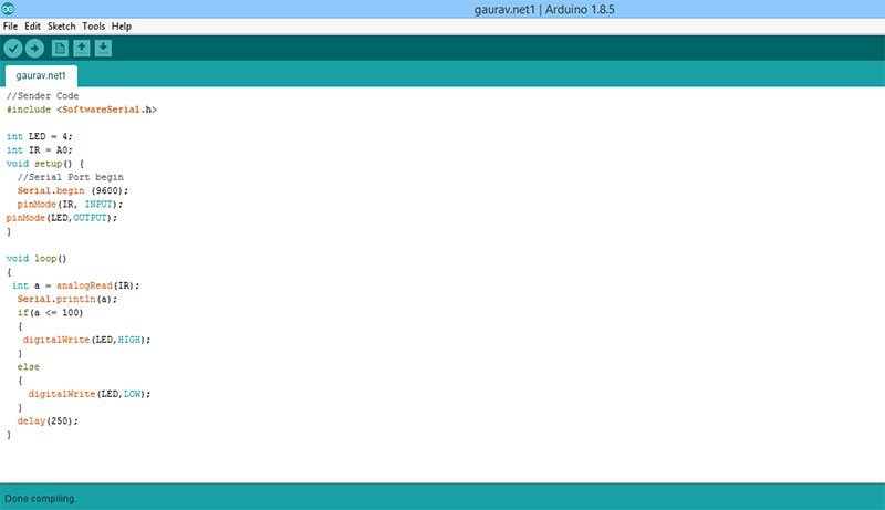
Checking input device on Modified Shashakit board ( My final project board )
I did this work in project development week , here i am writing this as i do want to test my final project board for input devices , so use IR sensor which i connect to my board , just like above board you can also program this as it have 328P AU ic so you need to change the board setting while uploading the code and connect all the programming pins such as miso , mosi , reset , vcc , gnd and sck of board to respective pins of fabisp or arduino based on with what you are programing this board

Program code for this
Get its Program file from here and for eagle schematic and board files and more info about this board visit my Project Development Page

This work by Gaurav wadhwa is licensed under a Creative Commons Attribution-NonCommercial 4.0 International License.