

Week 4
Computer Control Cutting
Checklist
Explained how you parametrically designed your files
Shown how you made your press-fit kit
Included your design files and photos of your finished project
Files of this week
1 Parametric comb fusion .f3d dxf
2 Press fit construction kit fusion .f3d dxf
3 Mini kerf book fusion .f3d dxf
Assignment
Group assignment:
Characterize your laser-cutter, making test part(s)
that vary cutting settings and dimensions
My contribution in group work is helping in laser cutting as
setting parameters for different operation
Individual Assignment:
Cut something on the vinylcutter
Design, lasercut, and document a parametric press-fit
Construction kit,accounting for the laser cutter
Kerf,which can be assembled in multiple ways
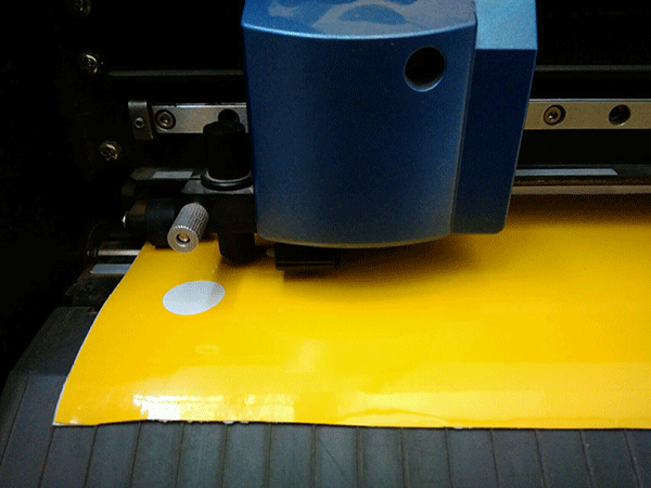
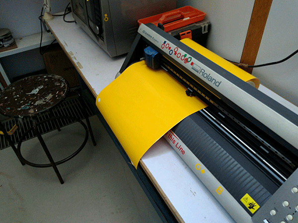
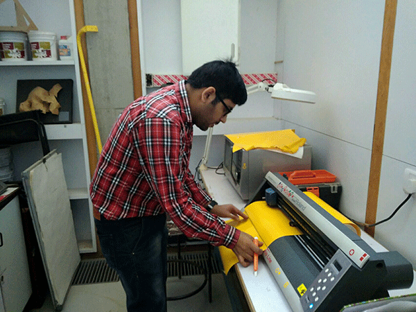
I started this week assignment with vinyl cutting machine , a vinyl cutter is a type of computer-controlled machine it look like computer printers. The computer controls the movement of a sharp blade like a knife. this blade is used to cut out shapes and letters from sheets of thin self-adhesive plastic (vinyl) this is also used for making flexible circuits
for vinyl cutting we have roland GX-24 in our lab and cut studio software so i started vinyl cutting by referring a video on youtube about machine and using cut-studio software
2 how to use GX-24 for basic vinyl cutting by jeff able at century college fablab
Setting up vinyl roll
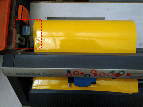
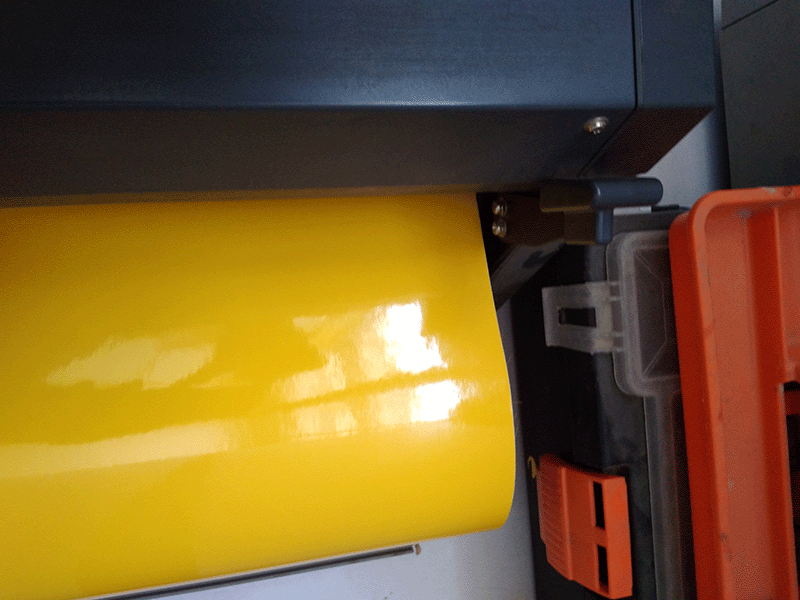
first step is to set roll in machine using a lever at back of machine , while inserting roll notice that the roller present there should be at the friction surface (white marks present in the machine ) .
click on force option to check force as we have preforce setting at 70 it depends upon Material Thickness
Open lever to insert sheet
Close lever
Notice sheet roller are friction surface
(white mark)

On machine
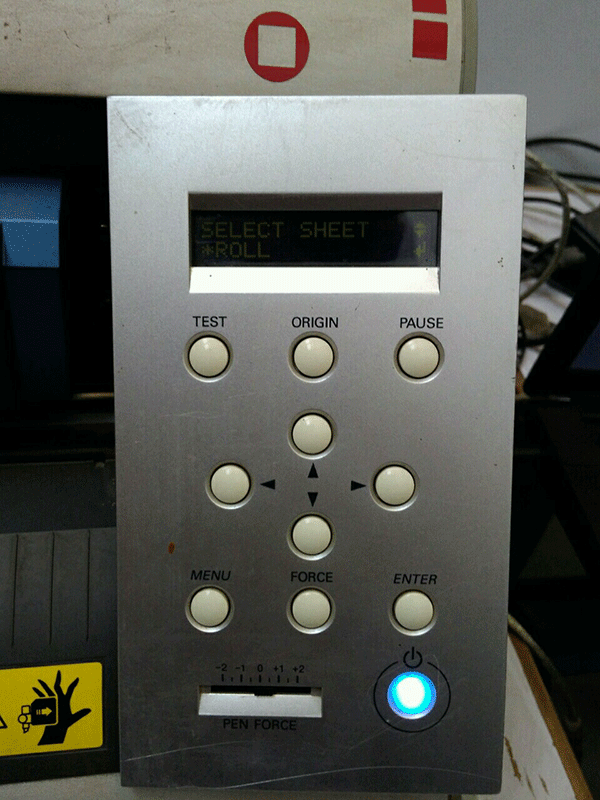
Select sheet type roll/ piece, press enter on roll as i have roll.
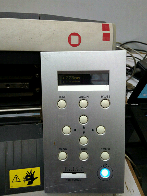
It will show you roll width here
w 275
Setting origin of machine
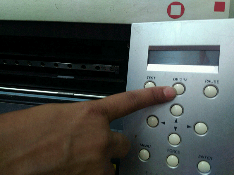
once the sheet is set , press the origin for the long so it will set the origin at start point of sheet and click on force to set it as 70 here i am using this as We tested this value on our sheet it may very so first give test print test for cheking force value
Test cutting
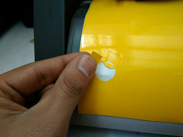
For test cut first set origin by pressing origin and Once origin of the Roland cutter is set so now press test button , it will make a square in a circle, I removed the vinyl cut from the main sheet and checked the cutting was properly done or not and it is proper so my force value is okay
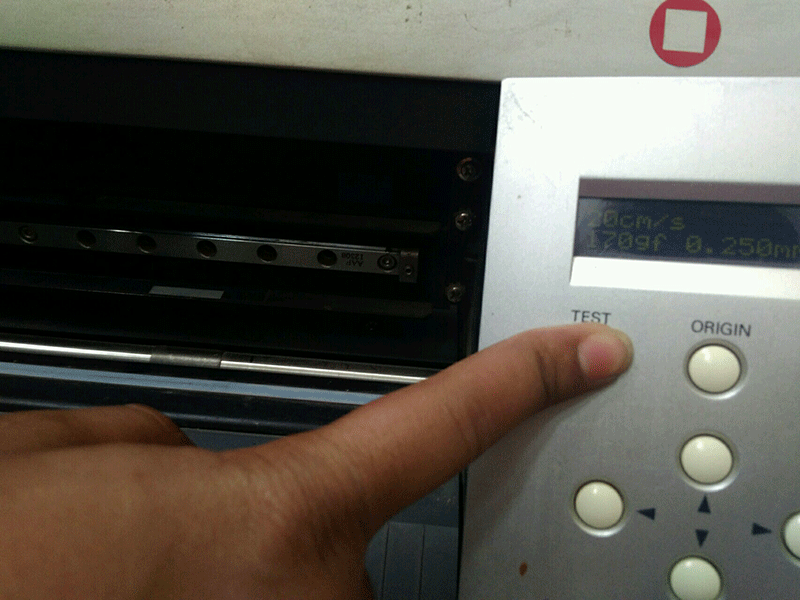
click on test for test print
check test cutting by moving sheet out
again set origin after doing test
Selecting image for cutting
For vinyl cutting you need to generate vector image as machine will cut actual outline of your image , so you need to extract outline of your image so select the image in which you can trace sharp image outlines for ex black and white images give better result ,
Image tracing and Cutting
i use cut studio software for image tracing and cutting process , this software have its plug-in for adobe illustrator and coral draw so you can use adobe illustrator or corel draw for better image generation .
Steps to use cut studio software
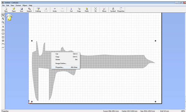
Step 1 : it is to load image in cut-studio ,the image is drag and dropped in the cut studio window or you can import using import option in file menu bar
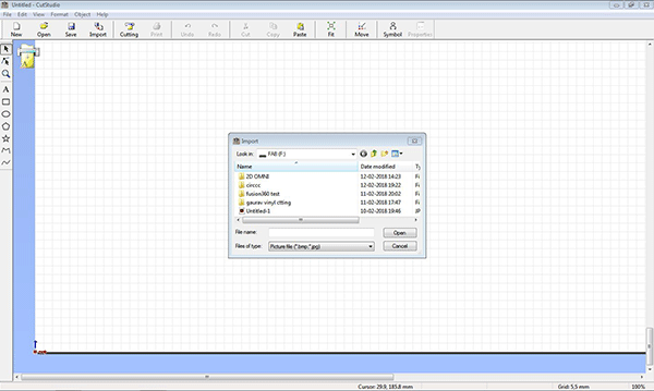
Importing file `
Click on properties
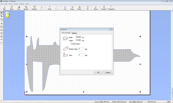
Resize image size
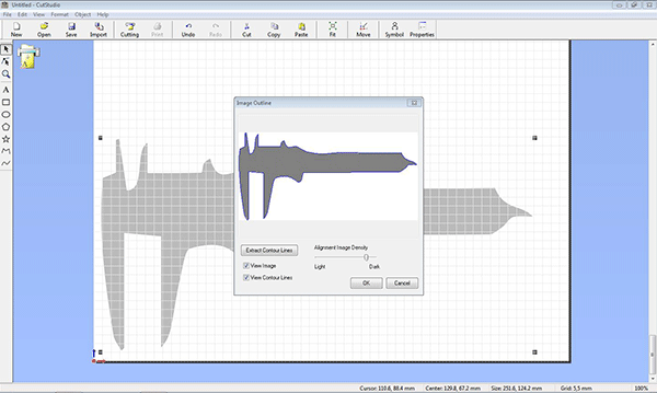
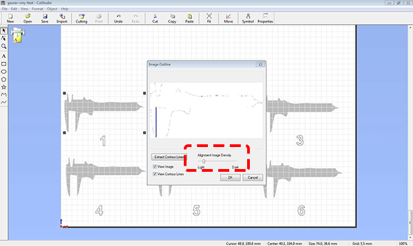
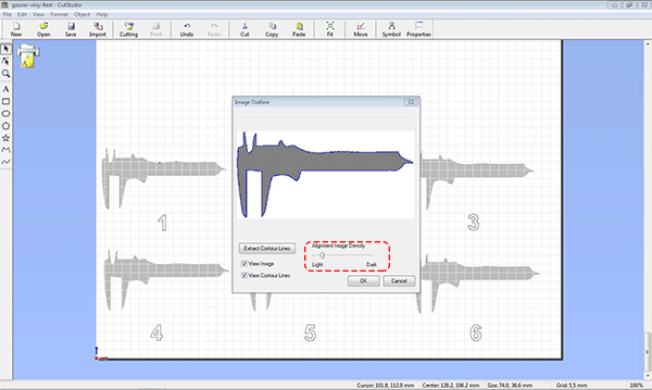
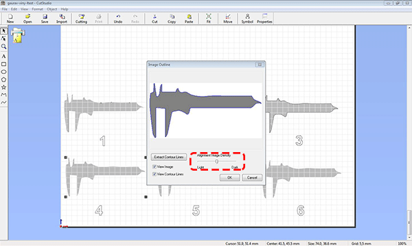
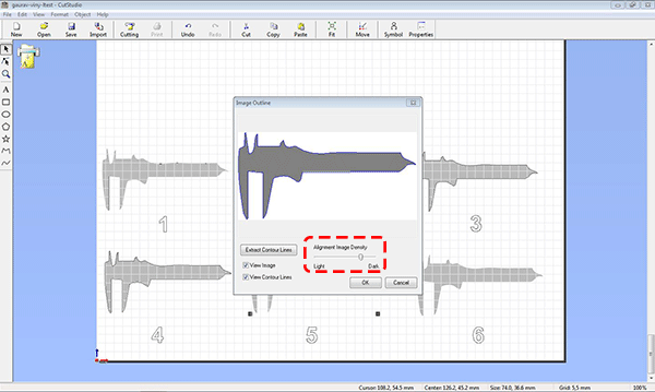
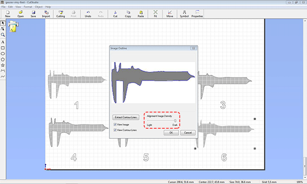
Step 2 you need to convert this jpg image into line drawing for which you have to select image outline, In image outline option you will find alignment image density set this and click ok to get image outline
Cutting
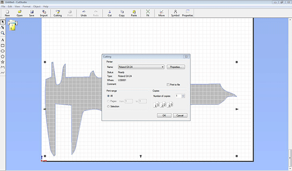
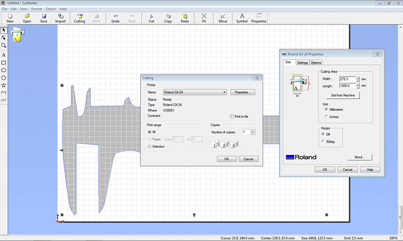
click on the cutting option on the top , go to properties , you will be asked for width and length if you are not sure click get from machine and set units in mm/inches and rotate setting to 0or 90 degree than click on okay , machine will start cutting
move sheet down by down arrow key
cut the sheet using normal cutter
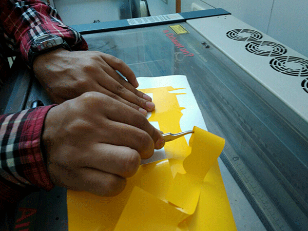
remove the extra material carefully by using twiser
this is how it get removed
Transferring Vinyl Cut
For transferring vinyl cut you may use transfer tape generally we use it when it is difficult to directly transfer it , i tried transparent self adhesive tape and paper tape for experiment but this things are not good and not recommended here this tape is very less adisive to sticker so i used this
.gif)
Best practices for vinyl cutting
1 for getting right cutting of vinyl sticker must do test cut varing force as it give you correct value of force so your sheet will cut nicely
2 remove the transfer tape slowly
3 you can use twiser for removing vinyl negative part as i am doing this thing
Experiment for exploring effect of image alignment density factor on cutting
For this i reduce down the size of image and place 6 images on screen as shown write 1-6 below them for indication as image alignment density varies from light to dark from1 to 6
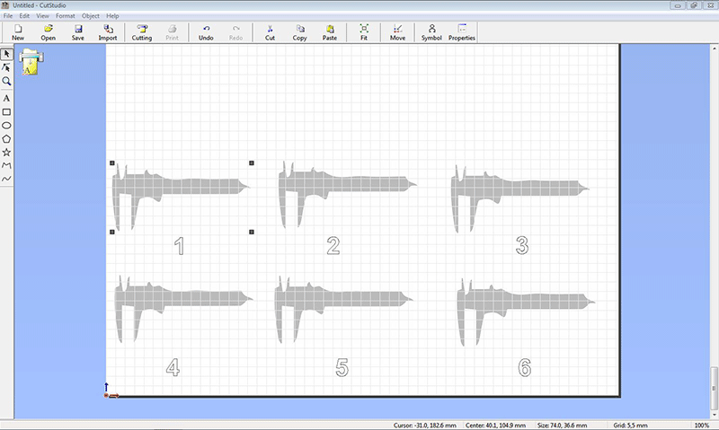
Now i assign different image alignment density to each image from light to dark
Extract counter lines for image 1
Extract counter lines for image 2

Extract counter lines for image 3
Extract counter lines for image 4
Extract counter lines for image 5
Extract counter lines for image 6
I deleted its background to see the lines
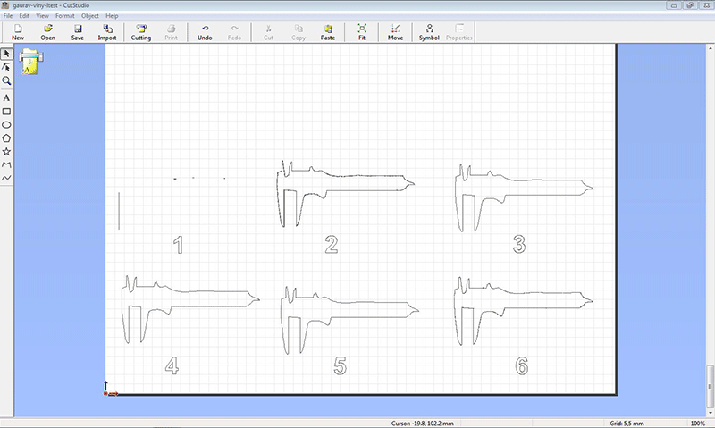
Observation
On noticing cutting lines keenly you found in image drawing
1 no visible cutting lines ,
2 cutting lines are not clear they are in steps
3 cutting lines are clear and properly visible
4 in this cutting lines are clear and properly visible
5 at vernier holding edges cutting line is not clear
6 lines are distroted from everywhere in image
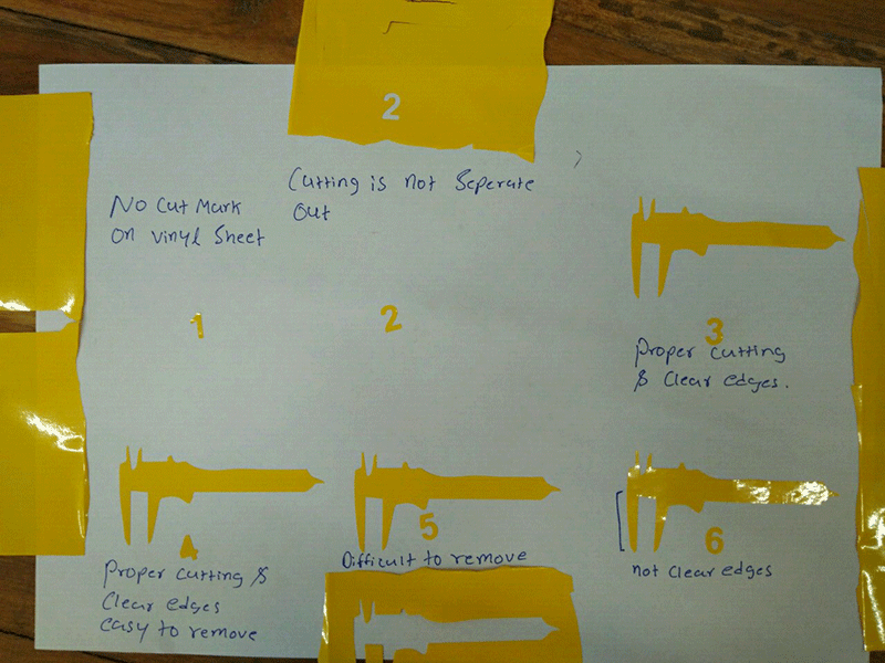
Conclusion
it is concluded that the image which is clear in drawing and have visible proper outside lines give proper cutting for this you have
to adjust the image allignment density to the point where you get visible neat and clear cutting lines i also did vinyl cutting in Week 17 and Project development Week refer both week to see my work
Laser Cutting
General steps for operating laser cutting machine
1prepare your drawing file for laser cutting
2 Starting the machine and its accessories
3 set cutting/engraving parameters
4 Setting up material and origin for cutting, focus point
5 Sending file to machine and start the cutting
Prepare your file for laser cutting
Usable formats .DXF
Compile all components in material size which you are going to bring here for cutting. And compile inside the reference box
Delete duplicate and overlapping objects
Join all the single objects and form a close boundary
Use layers/colors to differentiate different operation you want to do on machine
keep your drawing within 900*1200 mm as this is our bed size of laser machine it may very for any other machine
Minimum distance between two line for full cutting is 1 mm for MDF and Paper, its 3 mm for acrylic
Minimum distance between two line for etching/marking/half cut is 0.3 mm
Send design file for approval should be sent from same person who has booked the slot
For text etching, export it in line format (In Rhino explode text)
Perform a test print which is square of 10 *10 mm
Suitable materials for co2 laser
Allowable materials:
Pine MDF (up to 7 mm thickness)
Plywood (up to 6 mm thickness)
Casted acrylics (up to 15 mm thickness)
Papers
Non plastic boards
Wood (for engraving)
Veneers
Prohibited materials:
Polystyrene, polypropylene, polycarbonate
Plastics containing chlorine and fluorine content based material
Any particle board other than Pine MDF
Rubber (All Forms)
Casting resins
Any kind of Metal
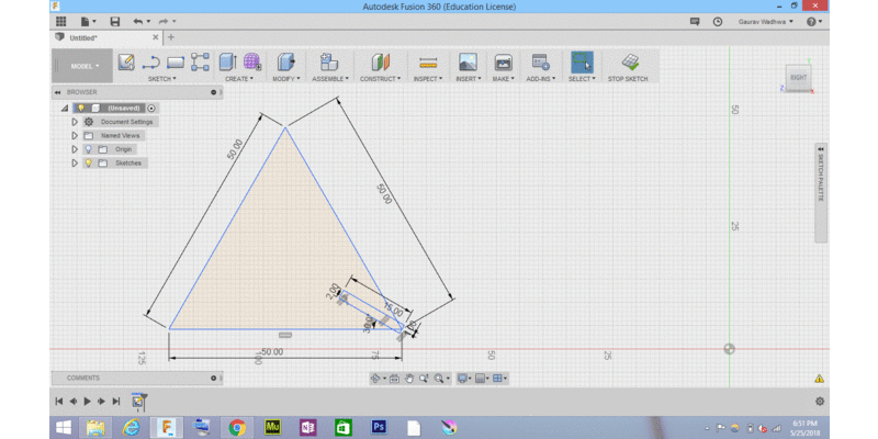
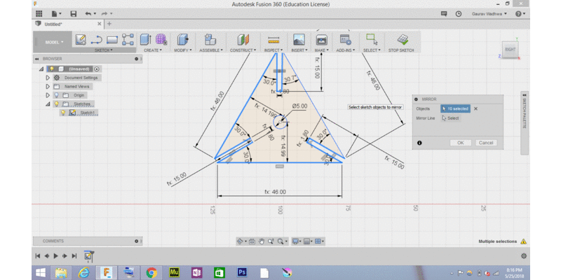
Parametric Desiging of Comb
laser cutting technique which uses high energy laser beam for cutting it is cnc controlled machine so you need to generate 2d drawing file for this ,it can perform cutting , engraving , marking ,we have 100w co2 laser in our lab of bed size 4* 3 feet
Task setup for this week
1 make comb for checking press fit
2 make parametric construction kit
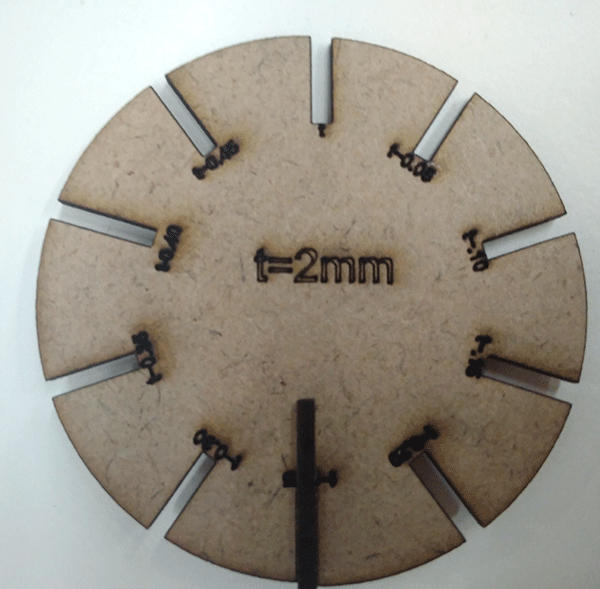
Making comb for checking press fit
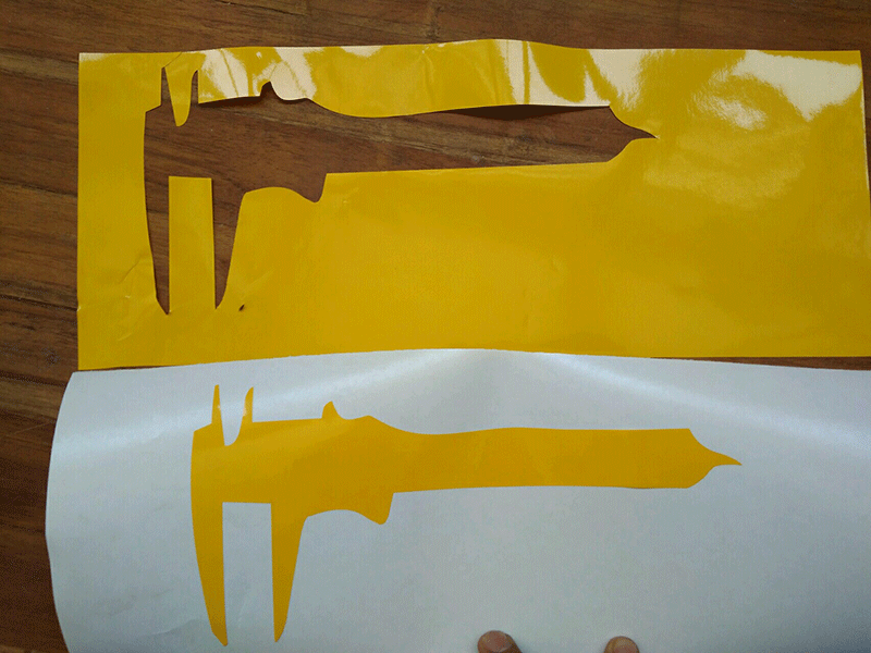
we are asked to make comb on different material and of different thickness so i try to make comb which is parametric and one can use this to test on any material of different thickness so i designed parametric comb i tested this on two material acrylic of 3.10 mm and MDF board of 2mm
.gif)
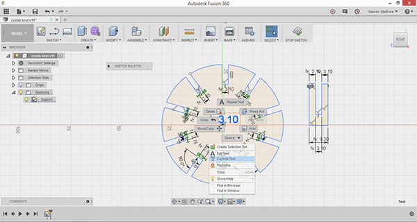
For testing this on different thickness change inner making by replacing value of t here (t=3.10) and explode text
Now change the value of t in parameter to 3.10 this is explained in GIF in next test in more detail

`
Testing comb on 3.10 mm acrylic sheet ,

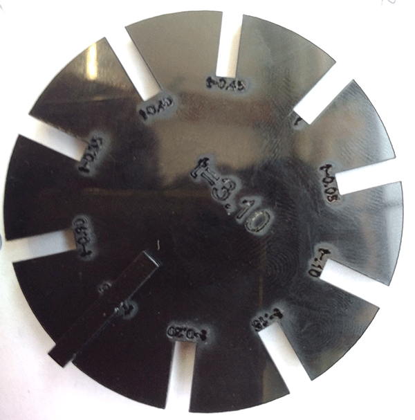
In doing comb test it come into notice that test piece fit perfectly into into t-0.25 that is 3.10-0.25= 2.85, now i have to design 2.85 slot for getting perfect press fitting
Checking parametric comb test on MDF of 2 mm thickness
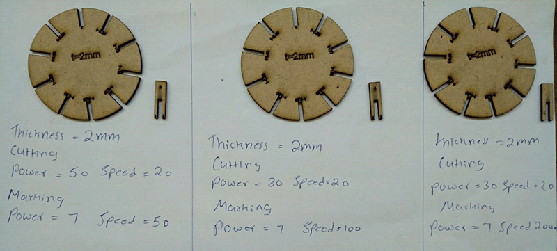
In this test piece fit perfectly into t-0.25 it shows for designing press fit kit for this material you have to give slot size of 1.75
Correction in comb
In above design of comb , My regional mentor Ohad suggest that the comb teeth ( test piece which i am inserting in comb) should reach to the center of circle so you can determine the correct fitting , so i redesigned the comb test piece and do changes in comb dimension .
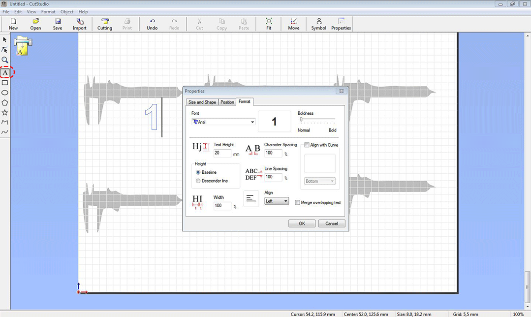
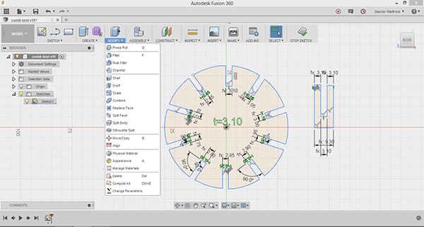
Method to change parameter of comb
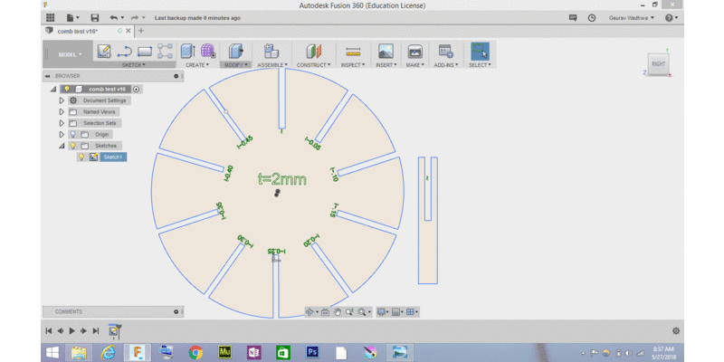
In this way you easily change the dimension of of comb to check this on different material i did this in 2mm and 3mm mdf get parametric laser cutting file in fusion 360 ( .f3d format ) here
.gif)
Setting the parameters in rd works software i.e setting the speed and power for cutting this thing depend upon the material thickness and material type
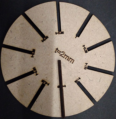
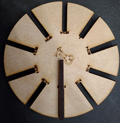
1 See here the teeth go up to center so i can check perfect fitting
2 Here it go inside t-.20 so the kerf of cutting is 0.2 mm in both
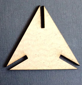
Parametric Press fit construction kit
we have to design press fit construction kit which can be assembled in multiple way for this i created a pattern , with notches which you can connect to form multiple press assembly , i created that in fusion 360
Steps for creating Parametric Pattern
for this create any pattern ( for ex here i am creating a triangular pattern with side notches so they will get press fit ) make the pattern with exact dimension ( i.e without considering kerf ) to check press fitting of it than measure the kerf and consider that also in designing
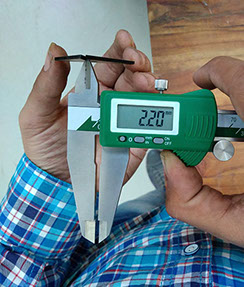
Measuring Material thickness and kerf of cutting
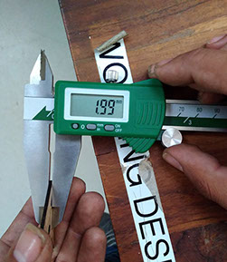
Material thickness varies from 1.99 to 2mm so i take 2mm in conideration
Measuring keft as in dimention i have given 2mm slot and it comes out 0,2 mm which is kerf of curtting
Test cut
on press fitting this comes out loose so i redesign considering kerf
Redesigning the Pattern

Making array of Pattern for laser cutting
Parameters for laser cutting
i am cutting this on 2 mm MDF board so the parameters i choose are in below image
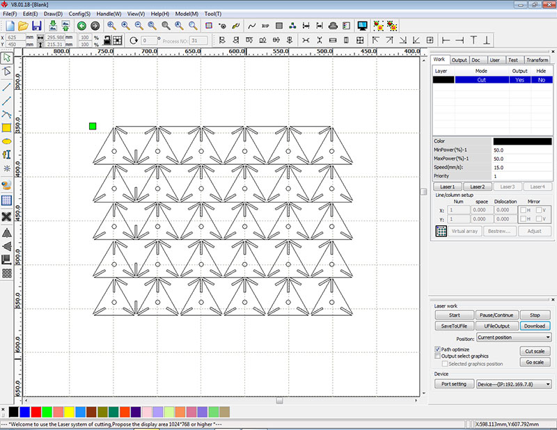
Laser cutting
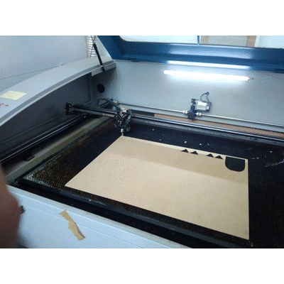

Testing kerf Pattern
testing kerf patten i did laser cutting on 2mm jute board
for testing i downloded thi sfrom instructable - link for original source
Video of testing pattern
i downloaded this pattern from Inscrutable link , design files of this is available on top and this kerf testing is done on 2mm Card Board Sheet
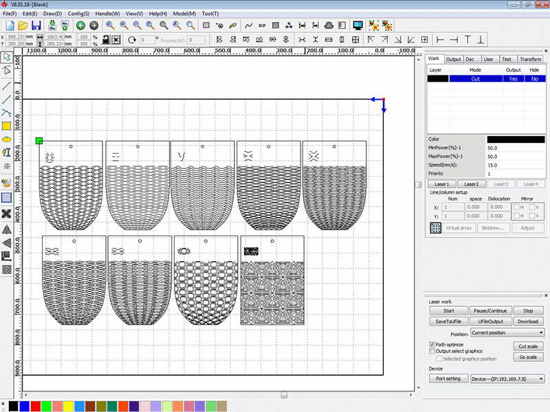
Desiging Pattern and Testing it
Learning from above patterns i start designing pattern for making tiny book cover
.gif)
Video of testing book
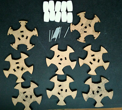
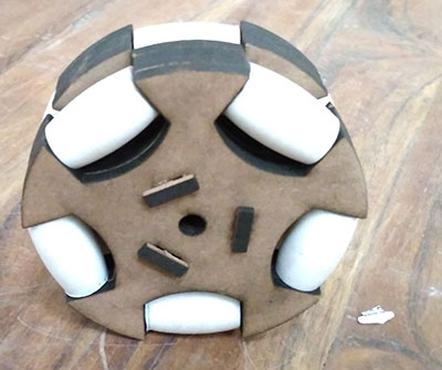
Laser cutting Omni wheel
I Made omni wheel using laser cutting and 3d printing for my final project as my final project , Refer my project development page for design files and assembly of omni wheel

This work by Gaurav wadhwa is licensed under a Creative Commons Attribution-NonCommercial 4.0 International License.