Exercise 10 - Input Devices
Weekly Assignment
Group Assignment:Measure the analog levels and digital signals in an input device
Individual Assignment:Measure something: add a sensor to a microcontroller board that you have designed and read it
Group Assignment
To measure the analog signals, we used a potentiometer hooked up to the ultrasonic sensor that we built for the individual assignment. We used a multimeter to see the changing voltage.
To measure the digital signal, we used the oscilloscope and probed both the trigger and echo functions of the ultrasonic sensor. The trigger pulses are very small because they are being measured as they leave the sensor, whereas the echo pulses are a bit longer because they are being measured as they return and thus the wavefronts are longer.
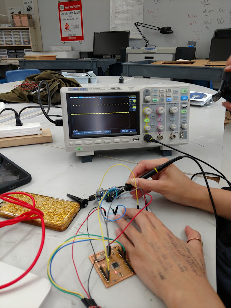
The small trigger pulses (about 10 microseconds in duration)
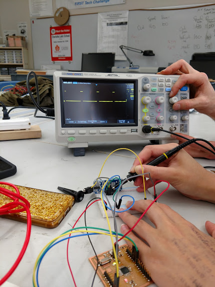
The larger echo pulses (about 200 microseconds in duration)
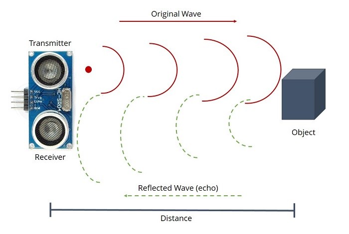
This image helps explain how the wavefronts spread out and are smaller for the trigger and larger for the echo
Individual Assignment
Building the BoardYet again, I was severely challenged by the week's assignment. So much of what we are currently doing are things I have never done before. However, there are tons of resources online and learning how to wade through them and find the good ones is turning out to be a very valuable skill. I decided to work from a board designed by a previous FabAcademy student, Daniele Ingrassia. His design, called Satshakit, and a tutorial are well outlined at this link.
This design was well suited for what I wanted to do, because it had extra ftdi pins AND, once set up, it mimicked the functionality of an Arduino Uno at a fraction of the cost. The extra ftdi pins also allowed for a variety of different sensors to be attached to the board, which I liked because I wasn't entirely sure which sensors I would be using. There were several different options on the page, one to be laser cut, one for cnc, one multi-core and one micro. There is a good table outlining the benefits of each. I realized I needed to use the cnc design, as I was going to be cutting this board on the Othermill.
Mainly following the tutorial, the steps I followed are outlined below:
- I chose the "satshakit cnc" design and downloaded two files ("internal" (for the traces) and "outline")
- Using fabmodules, I input and processed the files for cutting on the Othermill (.nc files)
- I then milled the design using a 1/64" tool for the traces and a 1/32" tool for the outline
- All of these procedures were previously written about in greater detail in Exercise 04 and Exercise 06
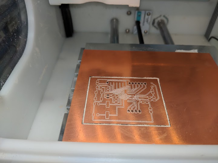
The board milling on the Othermill
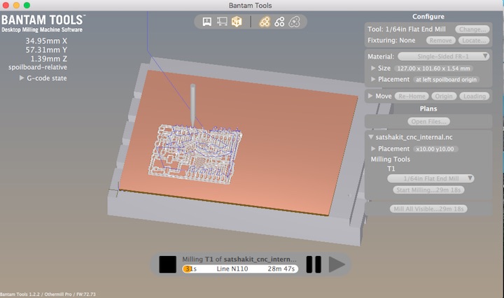
The toolpath for the traces on Bantam Software for Othermill
- Right click to download
- Satshakit Traces (.nc)
- Satshakit Outline (.nc)
Once the board was cut, I needed to solder the components on. Before I could do that, I had to drill the holes for the ftdi pins, because the Othermill did not drill those through. We used a tiny drill bit on the drill press and quickly knocked those out. The rest of the components were soldered in place. This chip, the ATtiny44, was a bit difficult to solder to these tiny traces. I had to remove it once and start over because it was slightly off-kilter and the traces didn't match up on one side.
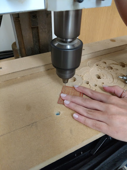
Using the drill press to drill the holes for the FTDI pins
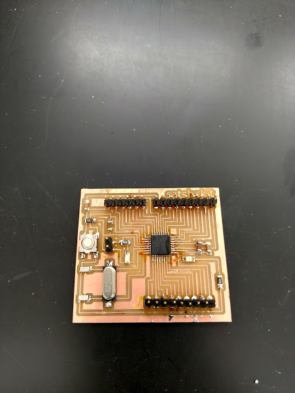
The finished board!
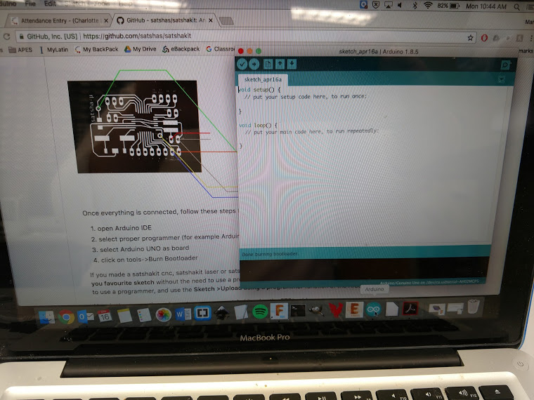
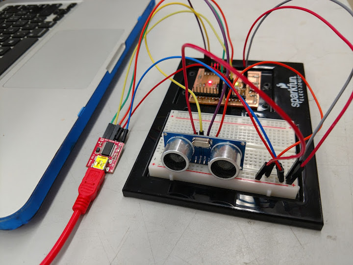
The next step was to get it working. First, I had to burn the bootloader. I used the image below to hook up the board to a Sparkfun FTDI Basic.

Difficult to get all this on a breadboard, but I did it
The process to burn the bootloader was fairly simple. In Arduino IDE, select the programmer (USBtinyISP) and the board (Arduino Uno) and then go to Tools>Burn Bootloader.
Success at burning the bootloader
Finally, it was time to actually see if the board works and then try adding an input device. I decided to run the simple "Blink" code to see if the board worked and it did, which was delightful. For my input device, I decided to go with the ultrasonic sensor because it seemed "cool". One of my labmates, Will Rudolph, discovered that Arduino has a web-based IDE that is much simpler to use because pretty much any library you might need is already built-in and you don't need to add any.
It works!! It can blink an LED
In order to hook up the ultrasonic sensor, I worked with this tutorial from HowToMechatronics. This tutorial works because the board I created works just like an Arduino Uno. Another great resource was this page from randomnerdtutorials. I got the ultrasonic sensor wired in to the breadboard and attached to my circuit board. Neil was right, using a breadboard CAN get messy.
All wired up and hopefully ready to go!
Finally, it was time to program it, which I also did in the Arduino IDE. Using the built-in libraries in the web based Arduino, I was able to search for and find some examples that used the HC-SR04 sensor. I compiled the program, uploaded it to the board, and it worked! However, the numbers flashing by on the serial monitor were going by too fast for me. I edited the code and added a delay of half a second so that it was only taking readings twice a second.
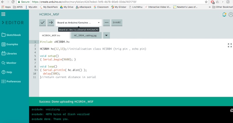
Arduino Code with Delay to Slow Down the Readings
It works! The readings are really accurate, also
All in all, this week was really hard but satisfying. The project had a lot of parts to put together, both literally and figuratively. I feel like I learned a LOT, though.
Final Project Board Design
So, knowing that I had to actually DESIGN a board and not just copy one from someone else, I decided to work on modifying the oh-so-useful and helpful Sastshakit cnc board. Below is an abbreviated list of the changes I made, some pictures of the planning process, as well as screenshots of the modified schematic, board, and FabModules output.
- Changes:
- Remove pins 5-9 and ADC6 and ADC7
- The above pins were removed to make space on the board for the ambient light sensor
- This board will be purpose built for my function
- However, I left the analog pins on top because of their I2C protocal capabilities, in case I want to add more sensors
- I also left a few digital pins on the bottom
- Added ambient light sensor and resistor in space created by removing the other pins
I took my sketched out ideas and went to Eagle to modify the Satshakit board. Pictures and files are below.
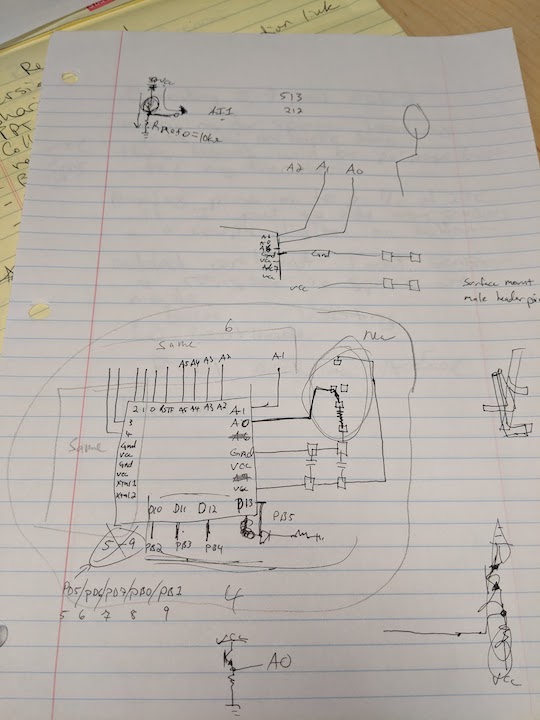
Sketching out what I want to remove and how the light sensor will fit
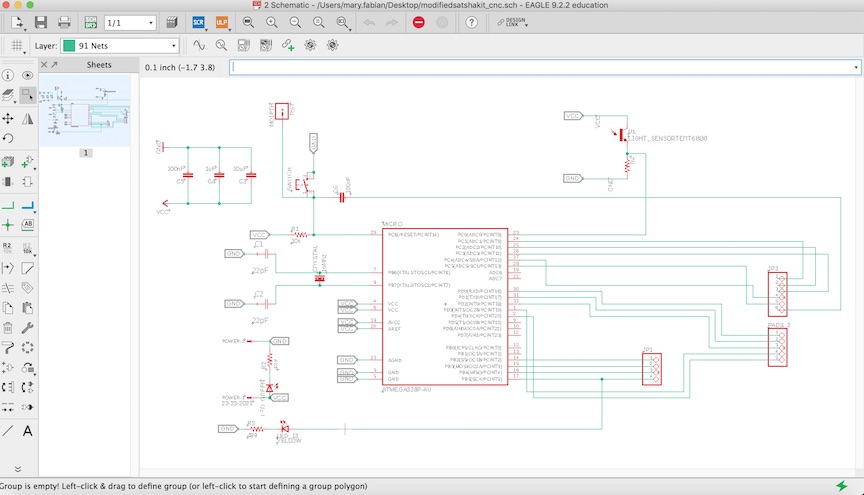
Here is the schematic in Eagle after I modified the original Satshakit
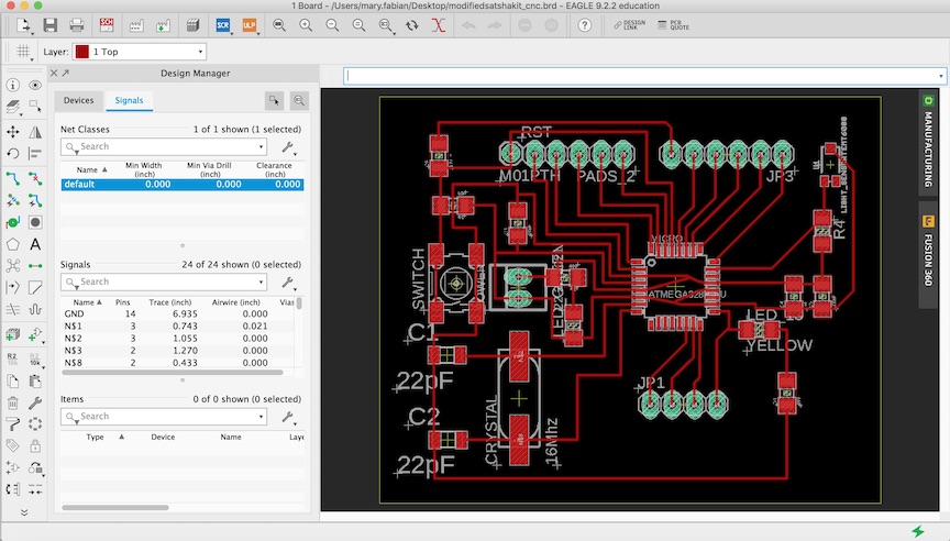
The matching board in Eagle
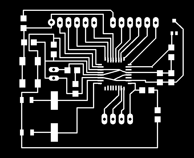
The board ready to export for milling
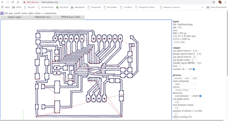
The .png after loading into FabModules and processing for the OtherMill (1/64" tool for traces, 4 offsets)

I also made an outline file to cut the board out of the material
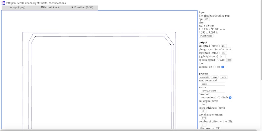
The FabModules setup for cutting out the outline (1/32" tool, 1 offset)
Download the .sch, .brd, and .nc files below
Modified Board (.sch)
Modified Board (.brd)
Modified Board Traces (.nc)
Modified Board Outline (.nc)
Sigh. Well, the best laid plans, so they say. I loaded up my files into the OtherMill, as I have done SEVERAL times before. It said it would take about 50 minutes, which seemed long, but whatever. I ran it, and thought it looked odd... really large on the FR-1 blank. Maybe this board was bigger for some reason? That didn't make sense, but I kept going.
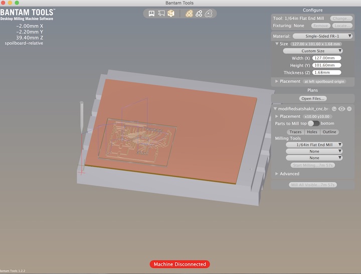
The final board file loaded into Bantam Tools, ready to be milled on the OtherMill
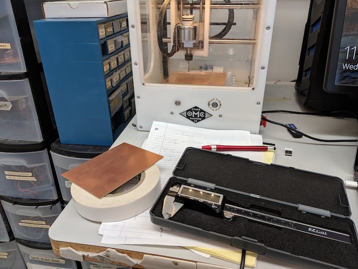
After extensive measuring and prep, milling has begun!
I soon realized that something was wrong, but I decided to let the whole thing continue. I started doing some more research while the milling was going on, eventually landing on the Bantom Tools Resource page for Double Sided Boards, as I couldn't find one for single sided. I started browsing through, congratulating myself for doing what they had suggested in terms of measuring and taping down. But then something in the step-by-step walkthrough caught my eye... "Import a double-sided PCB file. EAGLE .brd and Gerber files are both supported." I could import my Eagle .brd file?!?! I didn't have to go through all that exporting of a monochrome image, importing into FabModules, and calculating the g-code from that? I decided to try this, since when I pulled my board off the mill it looked terrible. Bits of copper were hanging off and some traces looked to be completely non-existent. So, I loaded the Eagle .brd file in and it immediately looked better. The size seemed more in keeping with what I was expecting, and the option to mill the holes and outline were there, also! I would not have to drill the pin holes?! This was so helpful and I am so glad I learned this!
Second attempt is being milled. Fingers are crossed!
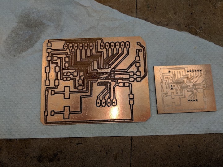
Side by side comparison of the two boards. The new one looks so professional!
I am still not sure why the g-code generated by FabModules was so far off, but I am extremely glad I learned that I can upload an Eagle .brd file into Bantam Tools for the OtherMill. That is a huge time-saver (and apparently mistake fixer). I've pulled all my parts, so on to the soldering!
All my parts are here and ready to solder!
I was not as ready as I thought I was. (Of course). I realized, upon showing pictures of the new board to my partner that evening, if you look at the upper left part of the board, that one set of pads had not milled out. I had no idea why? They were in the schematic and on the .brd file. The next day I went in, and sure enough, when I looked at the file the pads were there, but they would NOT import into Bantam Tools. I had to delete that set of pads and add a different set (I have no idea why), but this fix seemed to work. I was nervous about the TINY space between the traces on the board, so I decided to try to use Fabmodules again, and see if I could get more spacing with offsets. Long story short, I ended up making, in total, 8(!) boards before getting one that was the right size AND had spacing I felt I could work with. I also messed up soldering on 2 boards, before I finally got one that was not shorted out somewhere!
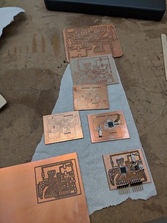
Here are the 7 failures. Some are the wrong size, some are not milled correctly, and some are not soldered correctly
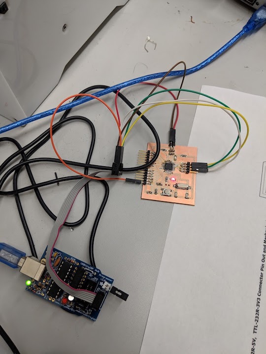
Success! Here is the board getting it's bootloader burned on
So, after a long string of frustrating failures, I finally got my board milled correctly, soldered correctly, and working. I burned the bootloader as outlined earlier. Then I modified some Arduino code to register the ambient light sensor and to turn the green LED on if the ambient light was below a certain level. To determine that level, I hooked the board up to the Arduino serial monitor and checked the numbers that represented different amounts of light. I decided that if the light value was below 100, it should register that as the cutoff and turn on the green LED.
The modified Arduino code to make the LED turn on when the light levels are low
The green LED turns on when the ambient light level is below the cutoff threshold and turns off when the ambient light level goes above the threshold
All in all, this was TOUGH. But I got it done and this board will work with my Final Project perfectly! I am pretty excited to be nearing the finish line.