Week 07 assignments:
- Make something BIG
- Test runout, alignment, speeds, feeds and toolpaths for my machine.
Leveling the spoil board
Before i even think about milling something i need to be sure the spoil board is
not crooked, so my first step is to level the board.
The working area of our milling machine is about 1 meter by 1.30 and you have to
use a large endmill if you don't want to wait for ages!
Large endmills can be a problem with harder materials but our spoil board is made
out of MDF and so i can use pretty aggressive parameters.
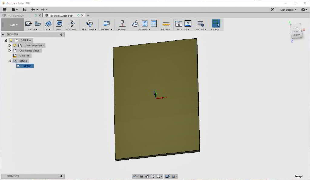
3D model of the board.
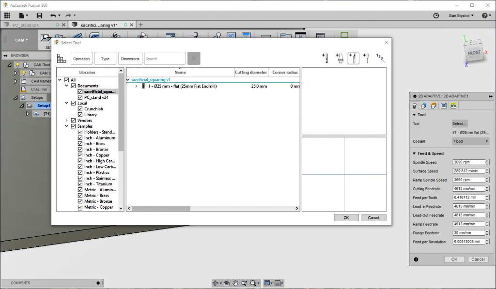
Selecting a large endmill for the toolpath generation.
I modeled a simple board on fusion360 and generated a 2D toolpath using the largest
endmill we have in our lab: 25mm.
I exported the toolpath as gcode using "grbl" postprocessor.
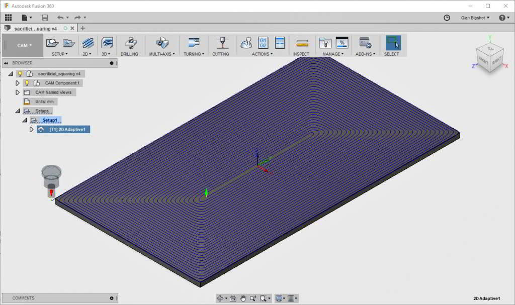
Leveling toolpath.
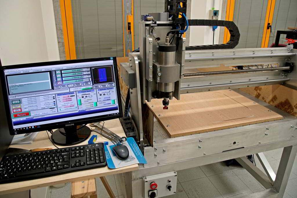
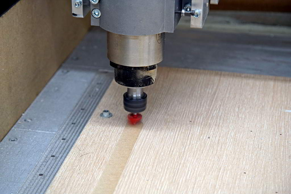
Machine setup before leveling.
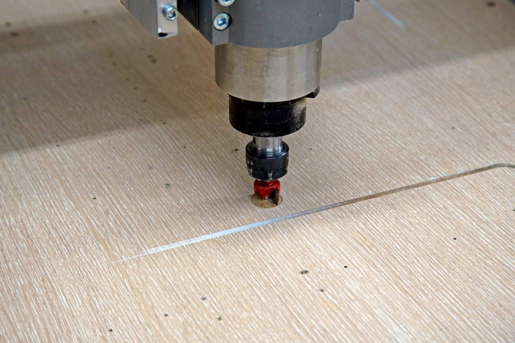
Zeroing the endmill.
Our milling machine is controlled by Mach3, i don't like its interface but it
works.
After homing all axis i zeroed Z axis "by hand" lowering the endmill by 0.5mm
steps until it touched the board.
Leveling in progress.
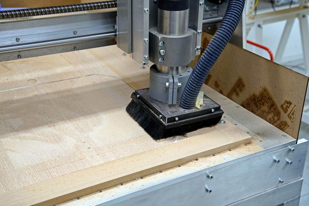
Better use the dust cap.
I repeated the leveling going down 0.5 each step and after a lot dust the spoil board was nice and flat.
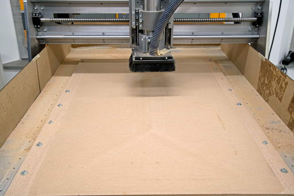
Spoil board leveled.
sacrificial_leveling.nc
Testing machine performance
I milled a test model to try to measure runout errors, compare up-cutting vs
down-cutting and try different spindle speeds.
I designed the model on Fusion360, it looks like a skull just by chance :)
It took a lot of time to generate the toolpaths changing all those parameters,
maybe it was a smarter choice to generate a gcode by hand or with some python
script.
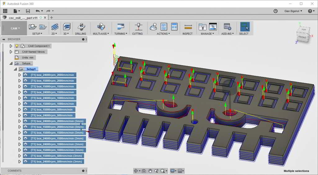
CAM toolpaths.
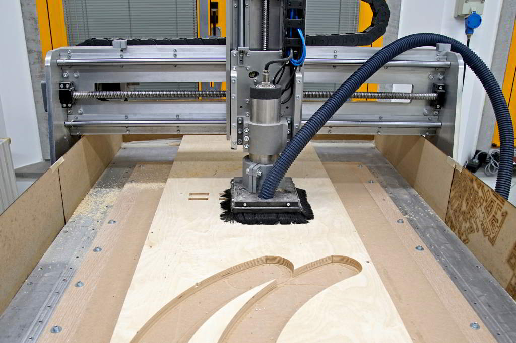
I used a 3mm 1-flute endmill on 18mm birch plywood.
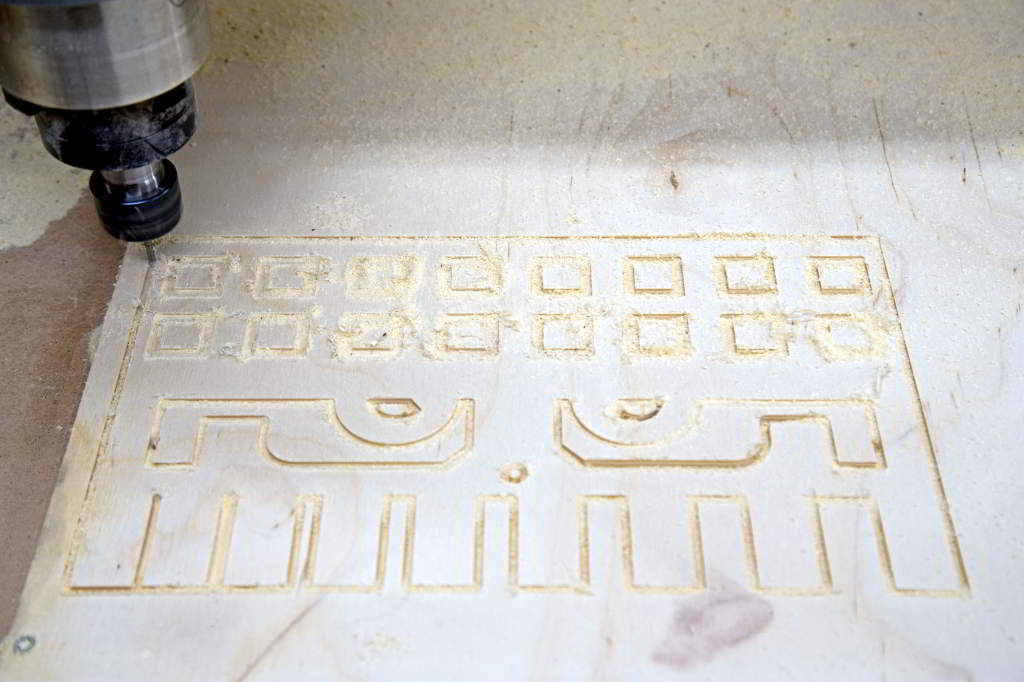
Machining in progress.
I calculated the runout measuring the space between the "teeth", it's under 0.1mm
but don't trust too much wooden surfaces against my hardened steel caliper.
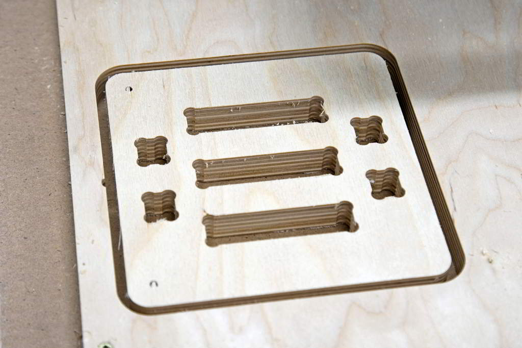
Scrap wood inside the "eye" milled using up-cut toolpath was ripped off but the
surface finish is smoother than the other "eye".
On the "forehead" i tested various spindle speed and feeds, at 2000mm/min the best
results are at 15000rpm or above.
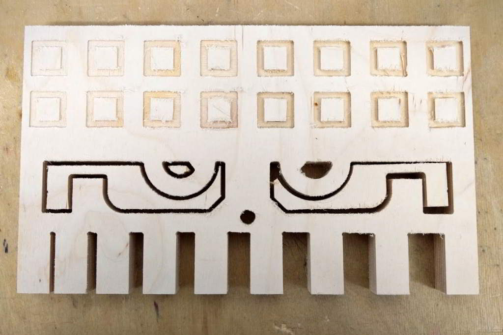
Test table completed.
cnc_machining_test.step
cnc_machining_test.iges
cnc_machining_test.nc
Articulated wooden arm for our CNC mill console
After testing our milling machine i realized that the console was a bit inconvenient.
So i designed and builded an articulated arm tha can be rotated o shifted at will.
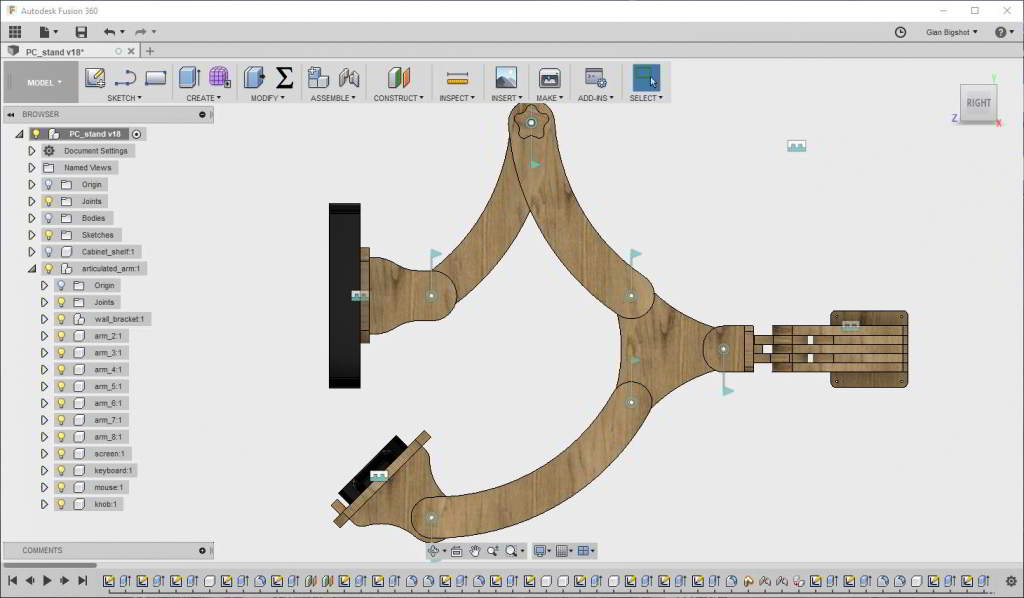
3D model.
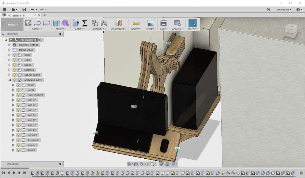
3D model with the wall and the nearby milling machine.
This design use a lot of joints, to compensate for endmill radius i used an external script for Fusion360 that generate dog-bones "automagically".

Using an external script to generate the dogbones.
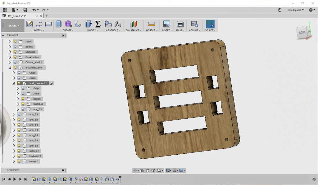
Dogbones generated.
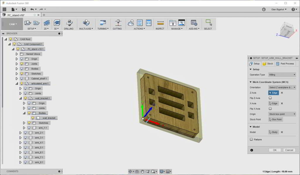
Selecting the origin of the toolpath.
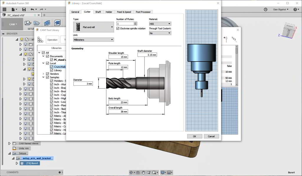
Design a new endmill in Fusion360 CAM.
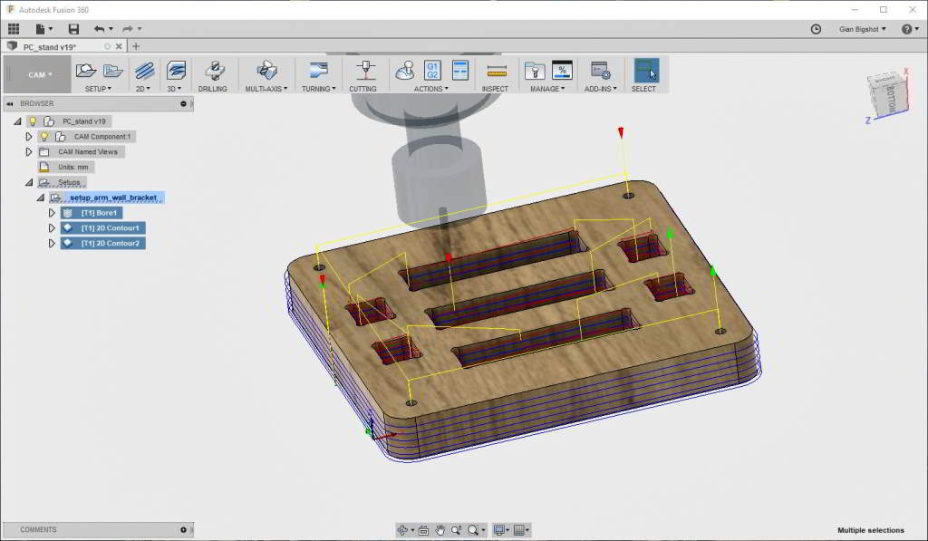
CAM.
I manually splitted M0 commands (rapid movements) in single axis commands because of a problem of the controller board. Hopefully we will repair it soon!

Splitting G0 commands to generate dogleg rapid movements.
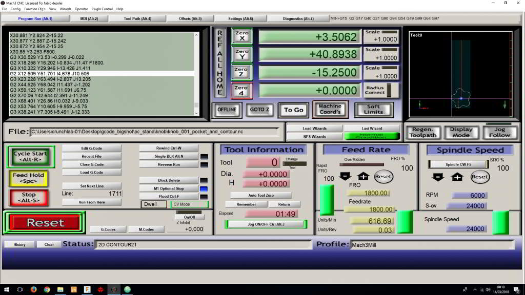
Mach3 standard interface.
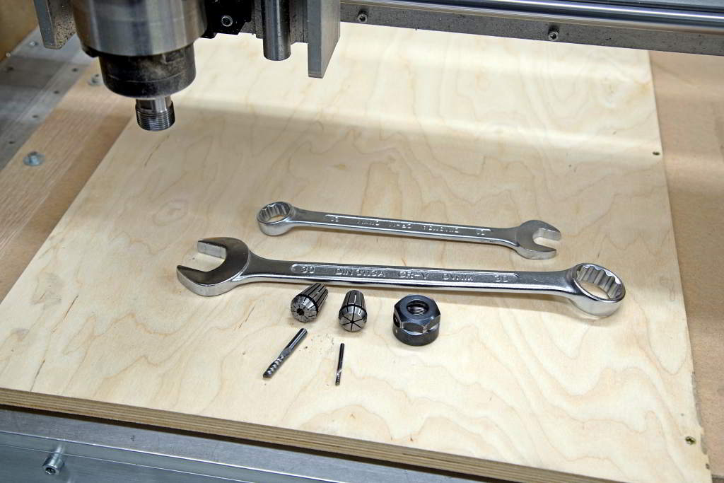
Collets and endmills.
The stock was 18mm birch plywood fastened with wood screws on the spoil board.
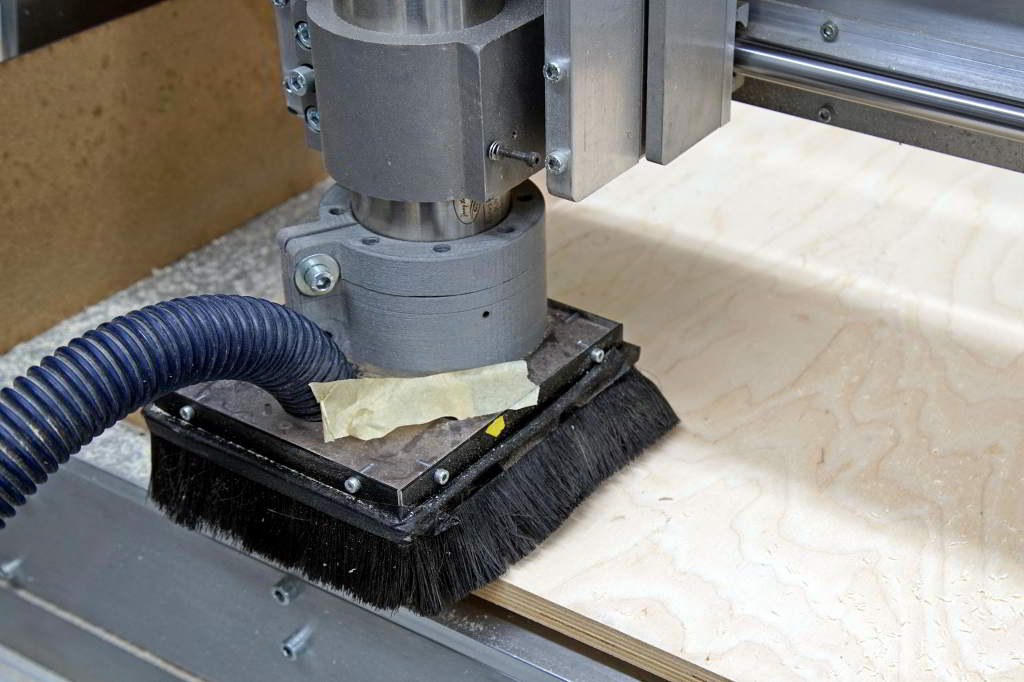
Milling birch pieces.
More machining.
Milled panel.
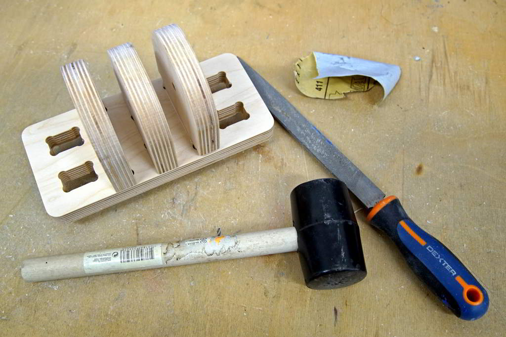
The assembly was very laborious and i needed to use a lot of "elbow grease" to
sand down every single piece.
Joints was very tight (i used the rubber hammer!) but i also used a bit od wood
glue.
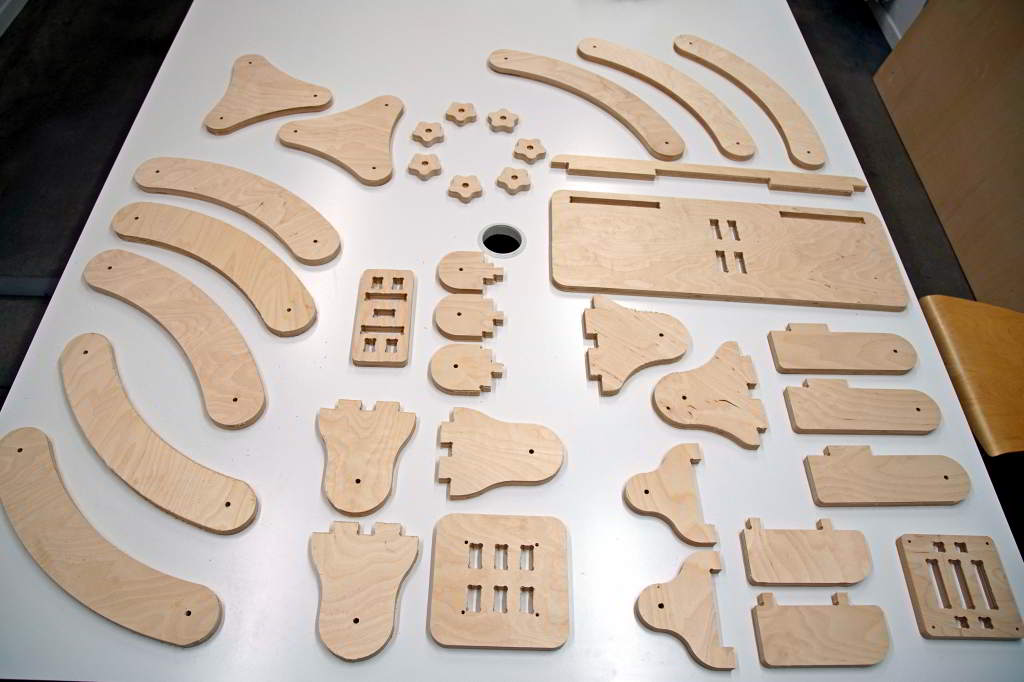
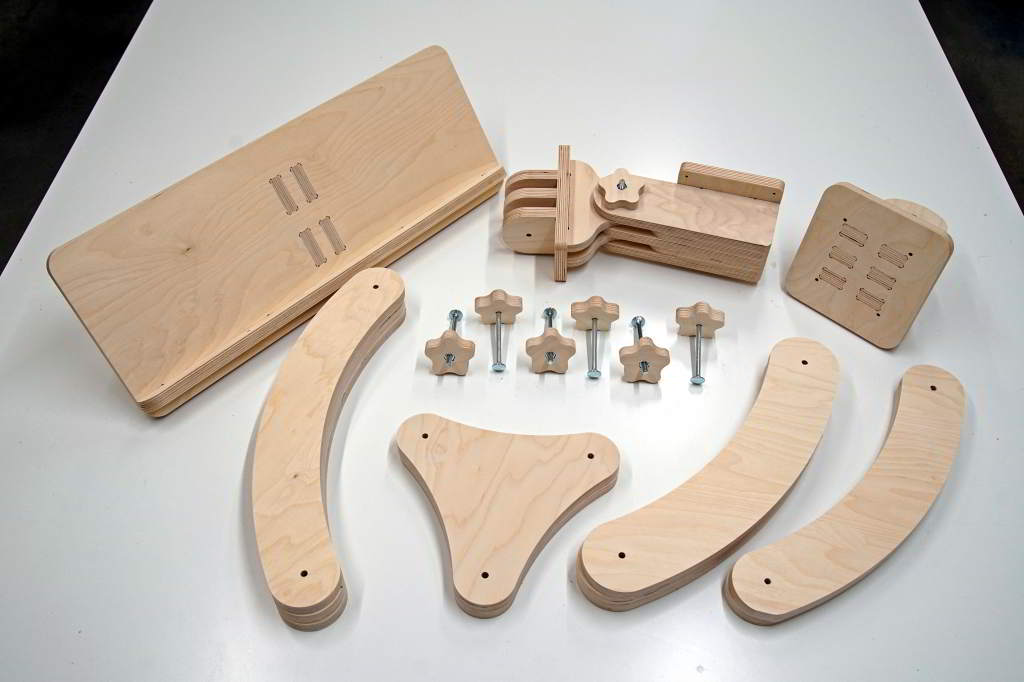
Full kit of machined parts.
Assembling the parts together.
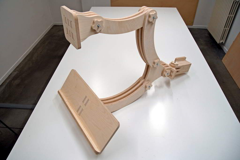
Sub-assemblies completed.
Hero shot.
2018-06-02 Update:
We are updating air milling machine using servo motors instead of steppers and we
are mounting the arm on the wall! :)

Super hero shot.
articulated_arm.iges
articulated_arm.step
articulated_arm_gcodes.zip
Bonus: Aluminium base plate for a 3d pritner
We just bought some chinese 3D printers that unfortunately have a very weak
acrylic frames, so I designed a "package" of reinforcements including a new
aluminum base plate using SolidWorks.
Anyway i like the CAM integrated in Fusion360 so exported and reimported the model.
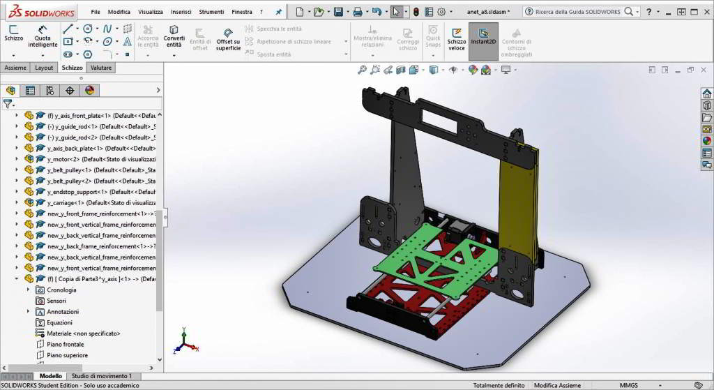
Base plate integrated in the 3D printer model.
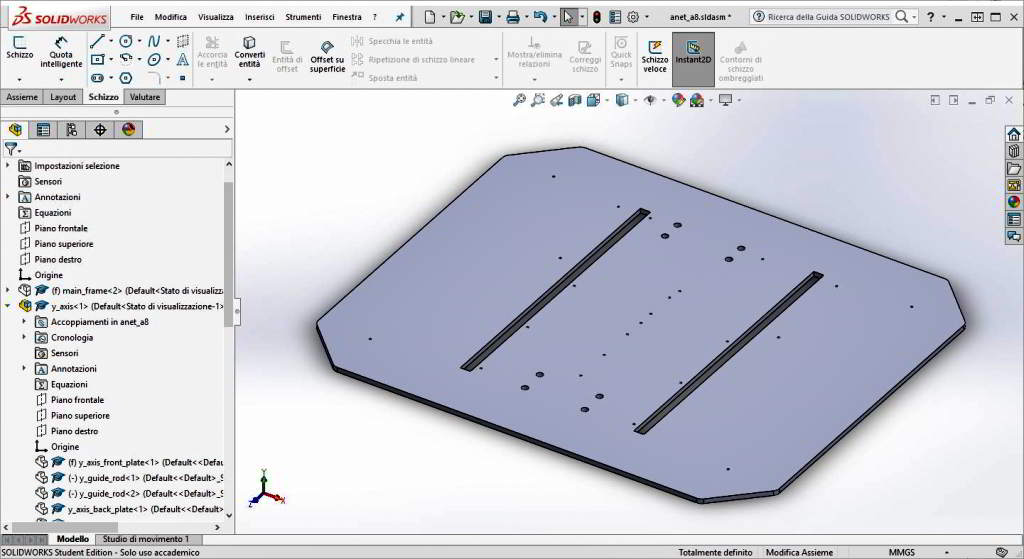
Base plate model.
Unlike wood milling parameters for aluminum need to be chosen wisely using
shallow stepdown and ramps.
After the initial holes are milled i planned to add some screws to block the
aluminum stock more firmly so i paid a lot of attention to safety heights.
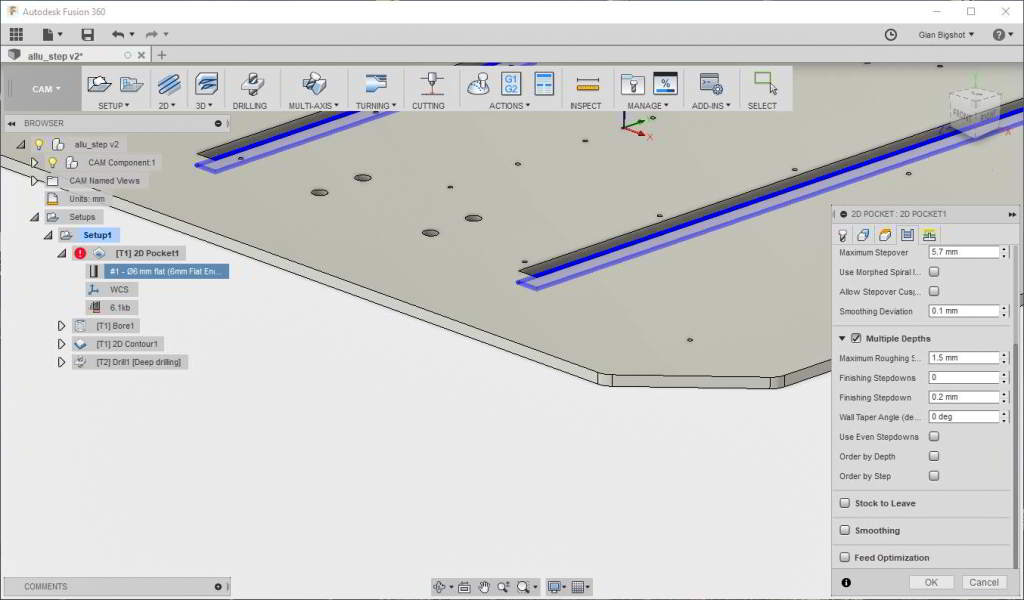
2D pocket toolpath generation: geometry to machine selection.
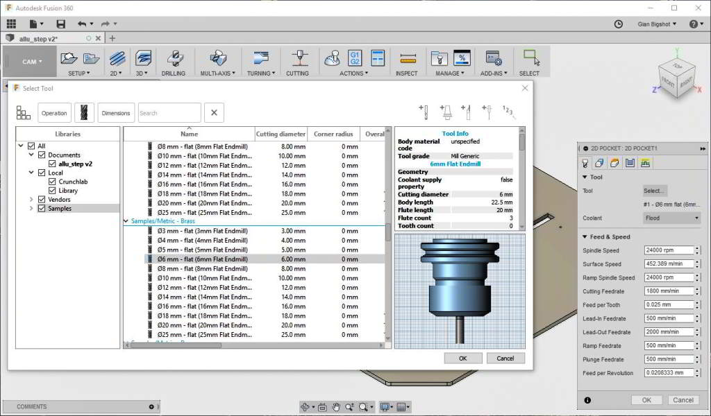
2D pocket toolpath generation: selecting the endmill.
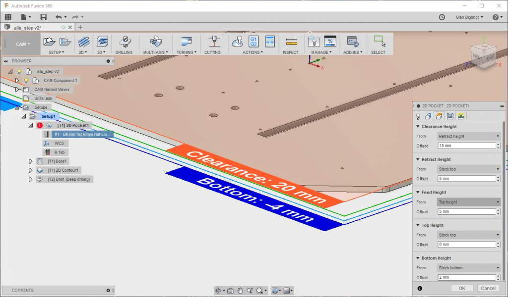
2D pocket toolpath generation: setting up safety heights.
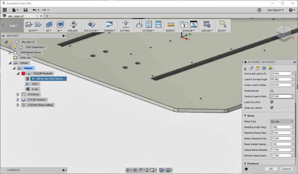
2D pocket toolpath generation: ramps parameters.
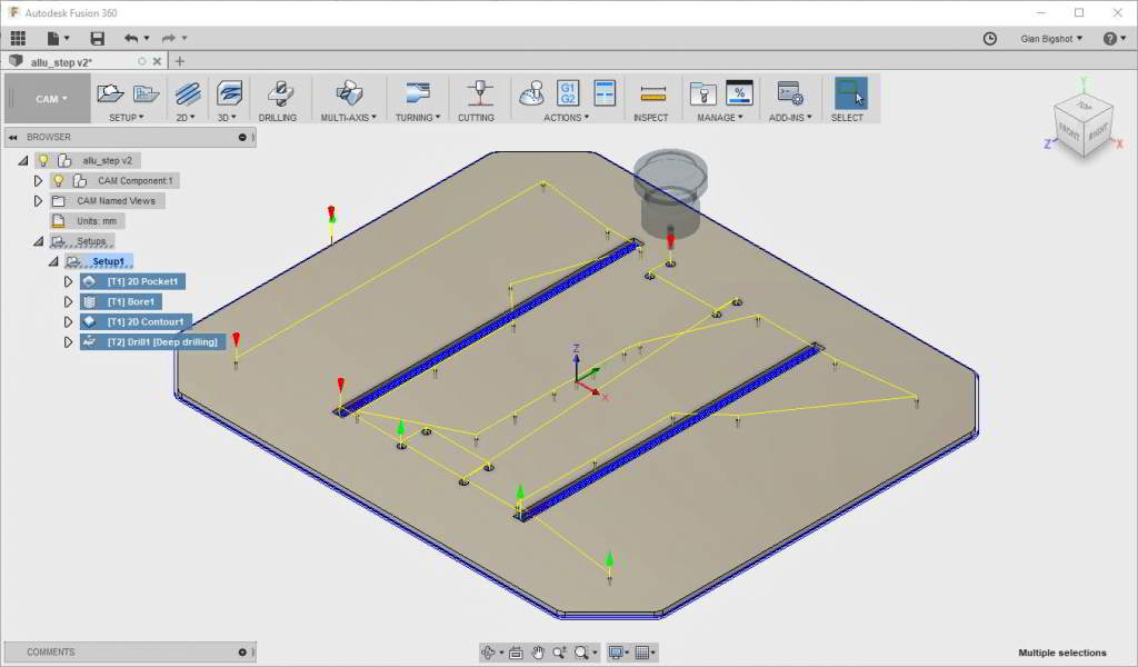
Complete toolpath.
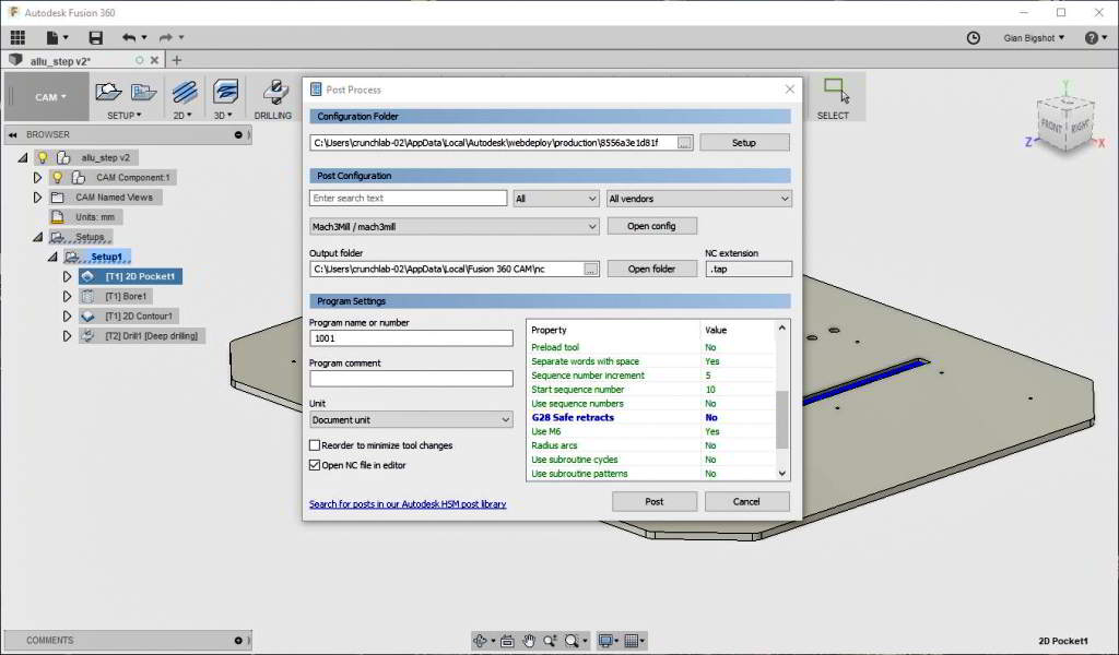
Exporting the toolpath to gcode using mach3 postprocessor.
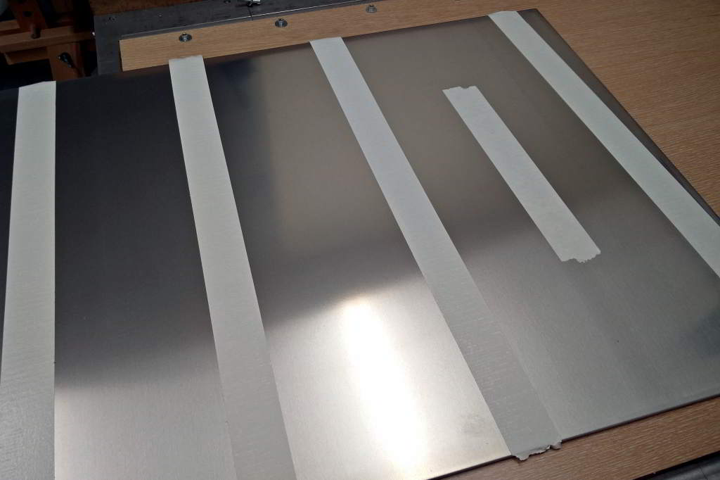
Double-sided adhesive tape is used to fasten the aluminum stock to the sacrificial.
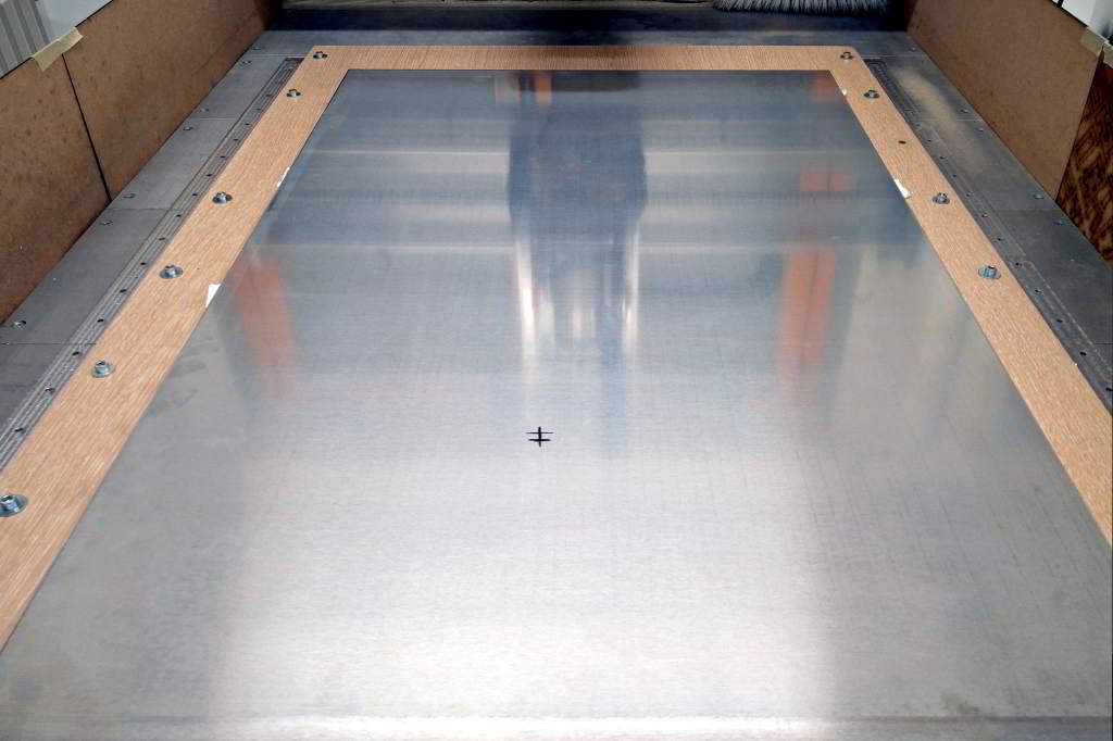
Marking the center of the toolpath con the stock.
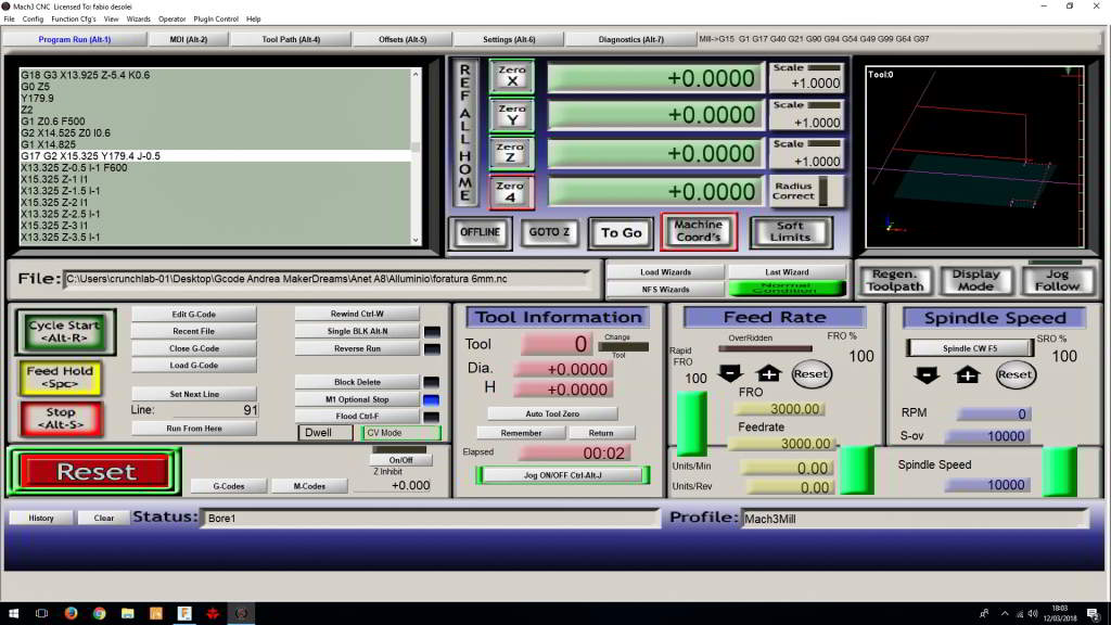
Mach 3 interface.

6mm flat mill.
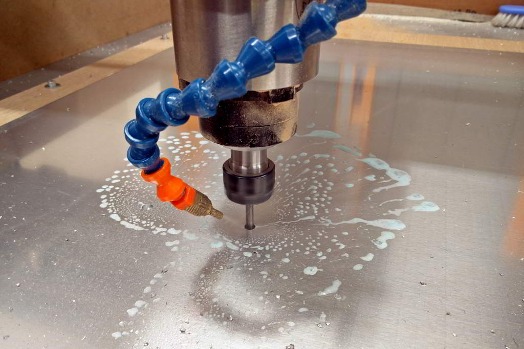
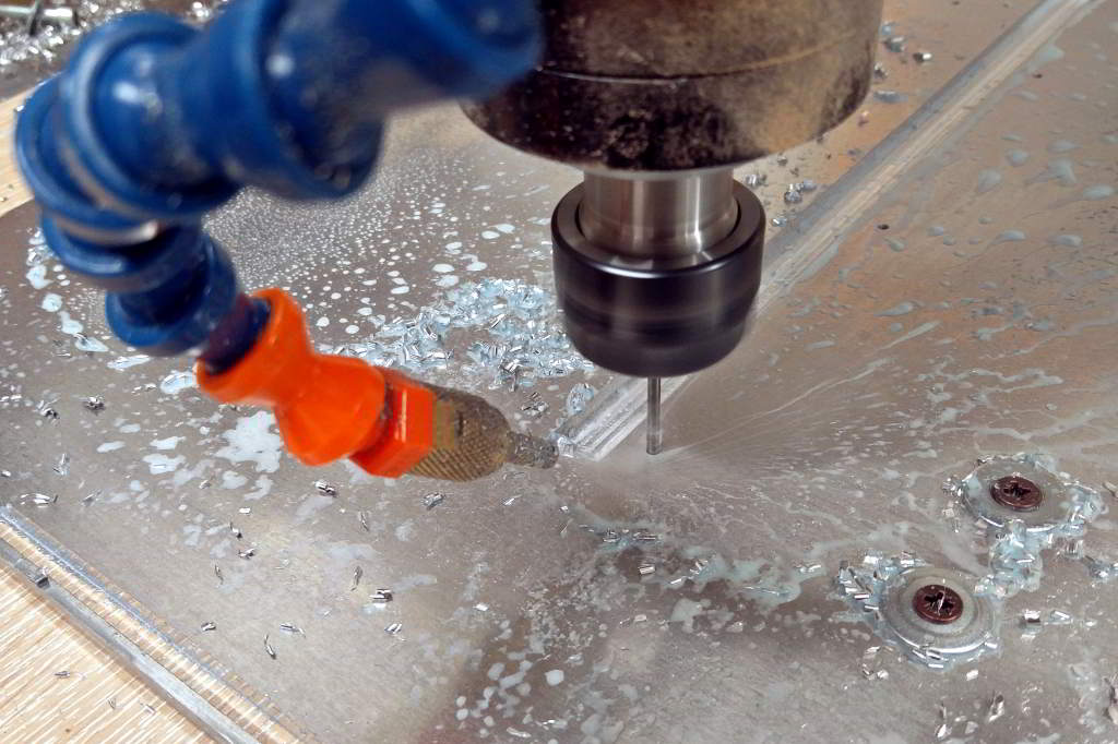
Machining in progress with coolant.
Milling in progress...
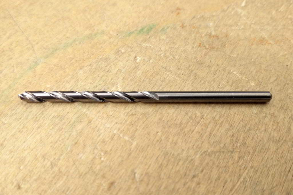
3mm drill bit.
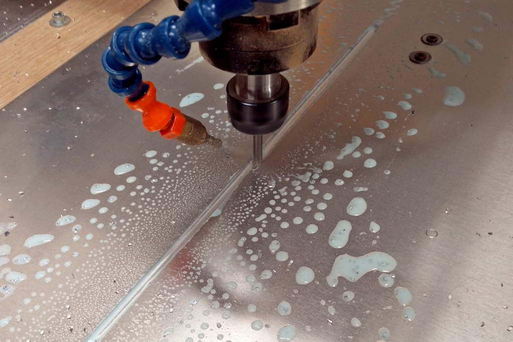
Drilling in progress with coolant.
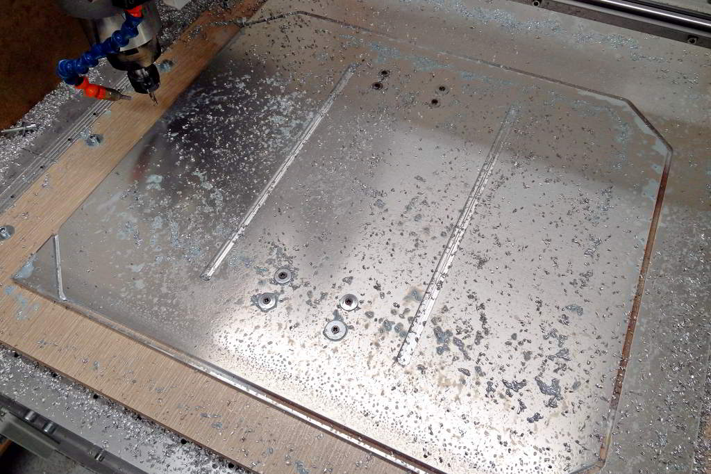
Machining completed.
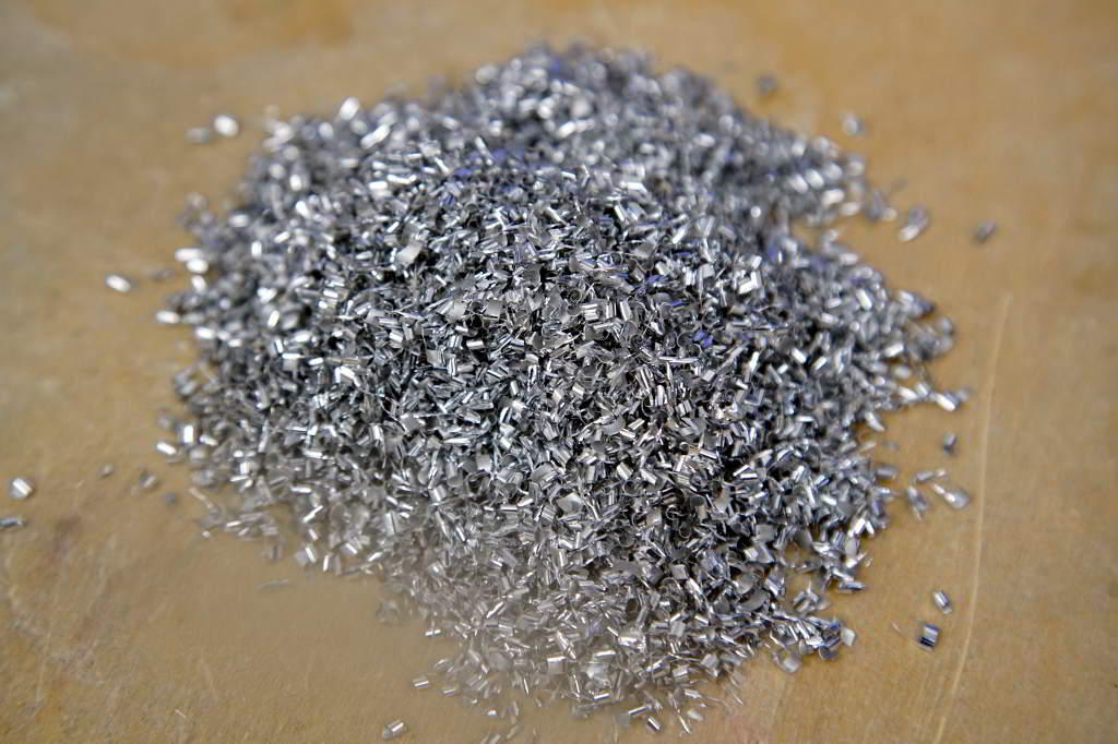
Aluminium chips.
anet_plate.sldprt
boring_4mm.nc
boring 6mm.nc
milling_6mm.nc