Exercise 12. Interface & Application Programming
Assignment: Interface and Application Programming
- Write an application that interfaces with an input and/or output device that you made, comparing as many tools as possible
Learning Outcomes
- Interpret and implement design and programming protocols to create a graphical User Interface (GUI)
Evidence
Process
MIT App Inventor
I wanted to create a phone app that would display my cats' activity (or lack of) on the cat wheel, tracking either revolutions or distance during each use. MIT App Inventor paired with HC-05 seemed like a good place to start. I was disappointed to see that it's only available for android phones at present but found the Android Emulator easy enough to download and use on my computer.
Reading through the guide and trying out the tutorials was helpful in understanding the programming environment and capabilities.
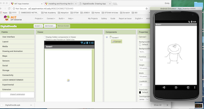
DigitalDoodle App on the Emulator
Blynk
Given that I:
- Don't have an android phone and
- Was advised to connect via wifi instead of bluetooth
I decided to simplify and switch from AppInventor to Blynk and from HC-05 (bluetooth) to ESP8266- ESP 12E (wifi module). The Wifi module will receives input from an app and transmits data to the app from my board. Meanwhile, I'd had a SNAFU with my input/output board after trying to mend some ripped up traces and was back to milling ad nauseam.
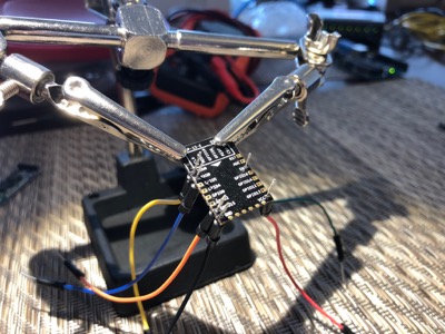
ESP8266 ESP-12E Wifi Module
Soldering
First step was to solder wires to the Wifi module so that I could plug it into a breadboard.
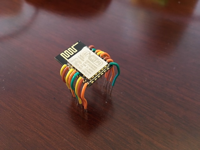
Next, I plugged the Wifi module with the wires into a breadboard. I found the datasheet with the pinout of the module and how to connect it for use.
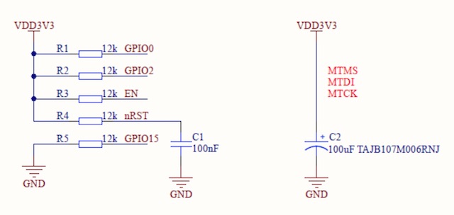
Circuit from datasheet
Wiring
I wired up the circuit as in the datasheet. I used the Arduino in the picture only for its 3.3V power supply. The module must be connected to 3.3V supply, and according to the datasheet, 5V will damage the board.
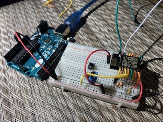
At this point, it seemed to be working because a blue LED on the module lights up briefly when it's powered up, and something called AI_Thinker appears on my iPhone Wifi network scan.
Arduino Installations
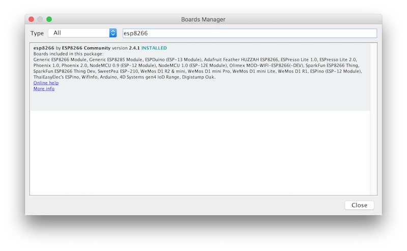
Next, I needed to install the ESP8266 libraries to use with the Arduino IDE. I needed to add the following link to my list of "Additional Boards Manager URLs" in the Arduino IDE:
And then I installed the board using the board manager
Blynk Setup
Blynk is a platform that allows iOS and Android devices to control Arduinos over the Internet. I installed the Blynk app from the App Store, registered, and received the auth token in my email.
There is a Blynk library available that work with the ESP-12E module. It must first be installed with your other Arduino libraries, as outlined in the Blynk Help Center.
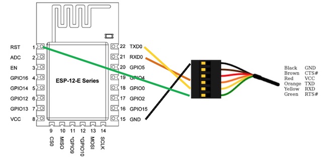
The ESP-12E is similar to an Arduino itself. You can use the Arduino IDE to upload sketches to it. In the Blynk library, there is a sketch called ESP8266_Standalone that uploads directly to the ESP-12E for basic control. To upload the sketch, I needed to connect the computer to the ESP-12E through a basic serial interface. I connected the FTDI cable connect like this:
I also had to modify the sketch with my own auth token and Wifi credentials:
#define BLYNK_PRINT Serial#include <ESP8266WiFi.h>#include <BlynkSimpleEsp8266.h>// You should get Auth Token in the Blynk App.// Go to the Project Settings (nut icon).char auth[] = "auth"; // I had my real auth token here// Your WiFi credentials.// Set password to "" for open networks.char ssid[] = "ssid"; // I had my real ssid herechar pass[] = "pass"; // I had my real password herevoid setup(){// Debug consoleSerial.begin(9600);Blynk.begin(auth, ssid, pass);}void loop(){Blynk.run();}
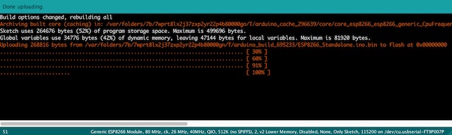
When I tried to upload the ESP8266_Standalone sketch, I got several error messages at the bottom of the Arduino IDE window:
warning: espcomm_sync failedAn error occurred while uploading the sketcherror: espcomm_open failederror: espcomm_upload_mem failed
I realized that I didn't pay close enough attention to the document. It tells you that to put the module into "flash mode," where it will send a program, you need to connect GPIO0 to low:
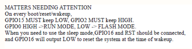
After connecting GPIO0 low, I was able to successfully upload the sketch to the ESP-12E:
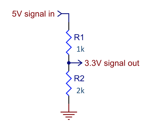
One small warning is that the FTDI cable I was using sends out 5V signals, but the ESP-12E module only accepts 3.3V signals, and I read that connecting a 5V signal might damage the chip. To get around this, for any signals being sent from the FTDI cable to the ESP-12E, I used a voltage divider circuit to convert 5V to 3.3V. An alternative would be to use a 3V FTDI cable.
I used the ESP-12E board first with a commercial Arduino because I've been having trouble getting any of my boards to be recognized from my Mac, despite hours of troubleshooting and assistance from both instructors.
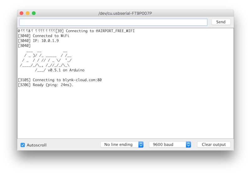
I then connected GPIO0 to high (run mode), and I was able to see the information on the Arduino IDE serial monitor. This was incredibly satisfying!
Project build
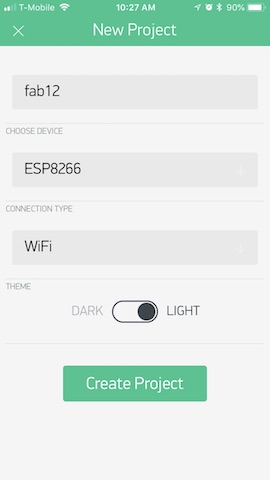
On the Blynk app on my phone, I created a new project. I thought I'd start simple:
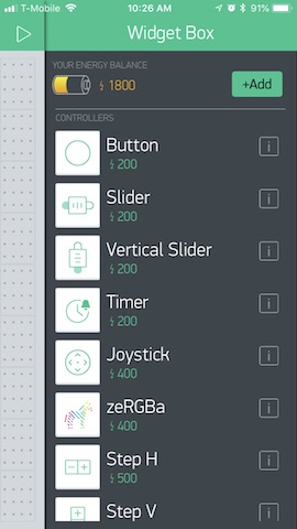
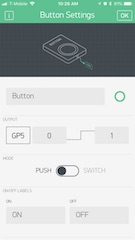
I added a button element from the Widget Box:
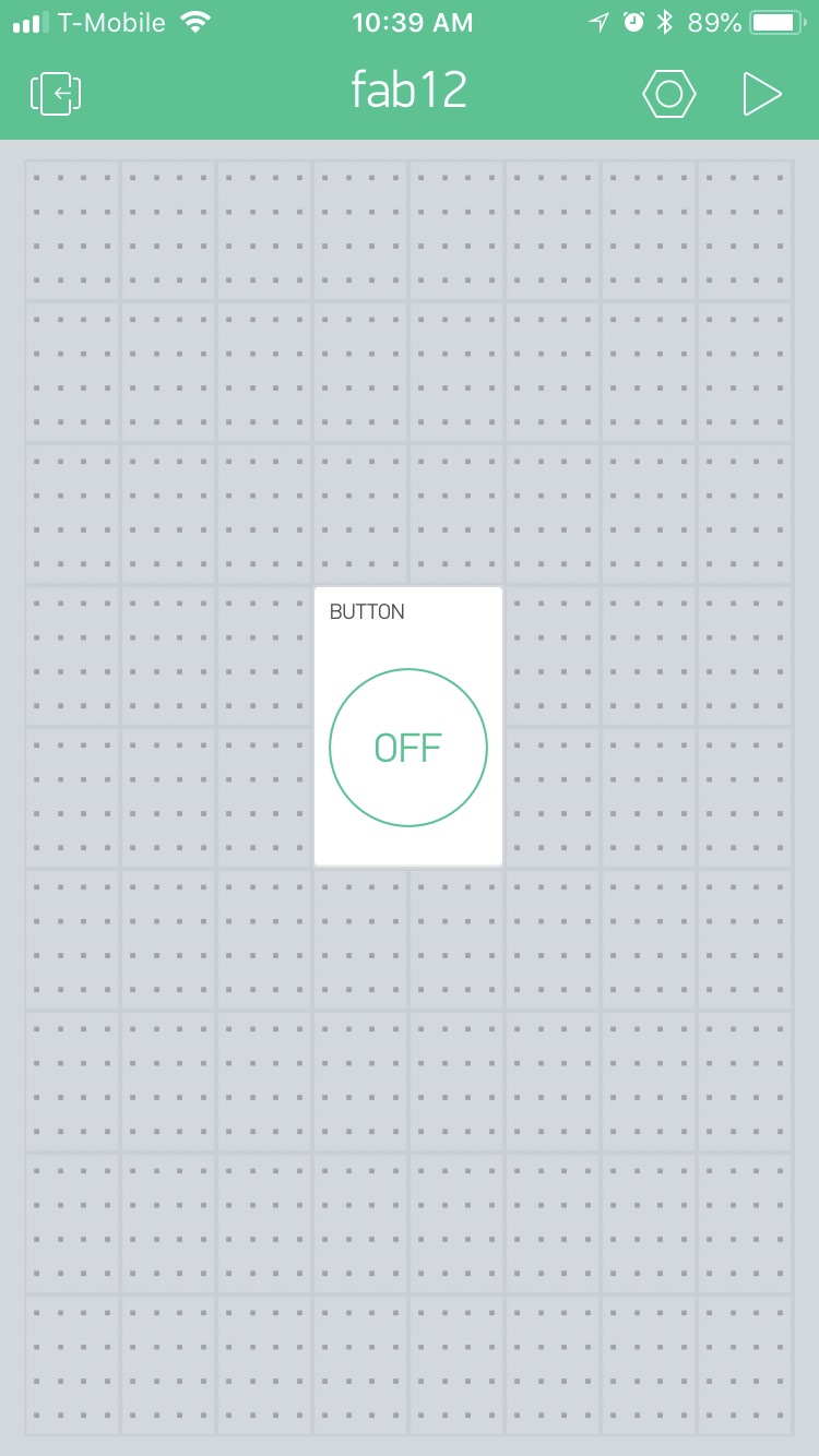
I placed this button in the project:
I configured the button to use output GP5, meaning GPIO5, which is a pin on the ESP-12E:
Now I have a project that looks like this in the Blynk app
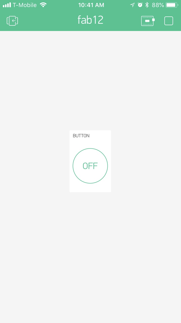
It's not quite the app for the cat wheel but making progress. I connected GPIO5 (pin 20 on the module) to an LED. Now when I press the button in the app, the LED lights up:
Sending Data to ESP-12E
The ESP-12E has a serial data port on pins 21 (Rx) and 22 (Tx). Below is the code from the Uno. It sends a number starting at 1000 and increments it by 5 every second. I had difficulty sending data between the boards. It worked only when I sent the integer number as a fixed length string (5 characters here):
// fab12_send_data.ino//// send example data through hardware serial port//int num = 1000; // This will be real data eventuallychar str[5];void setup() {// Begin the Serial at 9600 BaudSerial.begin(9600);}void loop() {itoa(num, str, 10);Serial.write(str, 5); //Write the serial datadelay(1000);num += 5;}
And here is the updated code for the ESP-12E.
// fab12_disp_data.ino//// receive data on serial port//#define BLYNK_PRINT Serial#include <ESP8266WiFi.h>#include <BlynkSimpleEsp8266.h>char str[10];// Get auth token from Blynk appchar auth[] = "auth"; // replace with auth tokenchar ssid[] = "ssid"; // replace with ssidchar pass[] = "pass"; // replace with passwordBlynkTimer timer;// This function will run once every secondvoid timerEvent(){// You can send any value at any time.// Please don't send more that 10 values per second.if (Serial.available() > 0) {Serial.readBytes(str, 5); // read incoming bytes}else {itoa(-1, str, 10); // display -1 if no data available}Blynk.virtualWrite(V5, str); // Write to virtual pin 5Serial.println(str); // Send to serial monitor for debugging}void setup(){Serial.begin(9600); // Debug consoleBlynk.begin(auth, ssid, pass);timer.setInterval(1000L, timerEvent); // Call every second}void loop(){Blynk.run();timer.run(); // Initiate BlynkTimer}
I based the above code on the ESP8266_Standalone sketch but I have added code to read from the serial port and write the data to a virtual pin in the Blynk app. The virtual pin (V5) is tied to a Value Display box in the Blynk app.

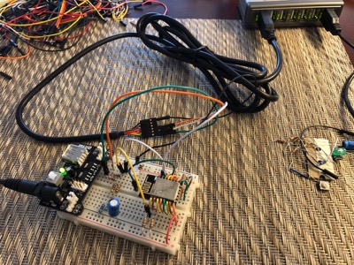
The Uno is connected to the ESP-12E breadboard with the orange wire, which connects Uno pin 1 (Tx) to ESP-12E pin 21 (Rx). The gray wire also ensures the grounds of the two boards are connected.
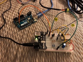
The Blynk app now displays the number being communicated from the Uno. It updates every second.
Set-Up with Modified Satshakit Board
In order to use my application with the boards I milled myself, instead of a commercial Arduino, I borrowed one of Dassault's Dell laptops.
I needed to go through the whole set-up of installing all the necessary software for Windows following instructions here and here. This process is trickier than software installation for Mac or Ubuntu but ultimately means I can use my boards again!
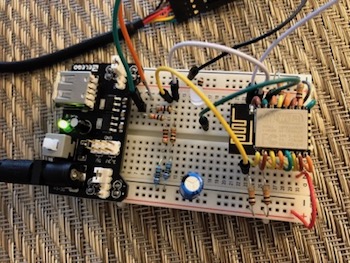
Once I could use the Arduino IDE with my board, I was ready to send the program via my FabISP.I connected my board to the ESP-12E breadboard with a wire that connects TX to ESP-12E pin RX. I also used another wire to connect the Ground of the two boards.
I set up my FabISP to program the Satshakit as I've done before and sent the Send Data code to this board.
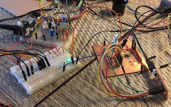
The Blynk app now displays the number being sent from the Satshakit, updating every second. It can also be use it to turn the LED on or off. To reset the number display, I used the reset button on my modified Satshakit.
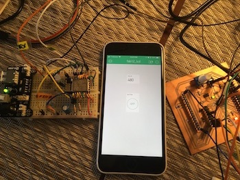
Close up of everything in action
It works!
Next Steps
Now that I have my board working with the app, next I plan to make an app that can display distance my cat travels (calculated from revolutions captured by the Hall Effect sensor) and uses the button to reset the tracker. Largely this will involve modifying existing code for the ESP-12E and the Hall Effect-LCD Display code I'd used for Exercise 11. Output Devices.