Week 09: Molding and Casting
Design a 3D mold, machine it, and cast parts from it.
Learning outcomes:
- Design appropriate objects within the limitations of 3 axis machining
- Demonstrate workflows used in mould design, construction and casting
Have you:
- Explained how you designed your 3D mould and created your rough and finish toolpaths for machining
- Shown how you made your mould and cast the parts
- Described problems and how you fixed them
- Included your design files and ‘hero shot’ photos of the mould and the final object
My Process
Background
I have a some theoretical knowledge/understanding of moldmaking and casting, but very little hands on experience. I hope also to become more familiar with Fusion 360's CAM tools by using them to mill my countermold. And I also wanted to use the Roland monoFab SRM-20 precision milling machine because I actually have one of those in my own Fab Lab and want to build my facility with it.
Getting Started
I started by brainstorming a list of possible mold-making projects. I asked myself the question: what would I like to make many of? And also, what might I like to make in a different material than I could 3D print (e.g. food safe materials, structurally stronger materials, high temperature resilient materials, etc. Here is the list I came up with:
Molding & Casting Ideas:
- nametag something
- high temp nozzle for heat gun
- hooks for headphones
- chess set pieces
- lego bricks
- lego man
- fidget spinner
- shoplight shelf bracket
- Lena park logo
- lena park Fab Lab coin/token (metal)
- star wars space fighters (x-wing, tie fighter, y-wing)
- green army men
- storm troopers
- lego brick ice cube tray
- lego brick lollipop tray
- lena park lollipop tray
- rocket body, fins
- drone parts (e.g. rotor blades)
- tin soldiers
- tin yoga poses
- yoga men (like "yoga joes"_blank")
I was interested in doing something food-safe (e.g. silicone ice cube trays, chocolate molds, lollipop molds) or higher temperature (e.g. casting something in low-melt bismuth-based alloy). When I learned that our lab had some Smooth-On Sorta Clear 37, which is food safe, it tipped me toward my favorite idea: lego brick ice cube trays.
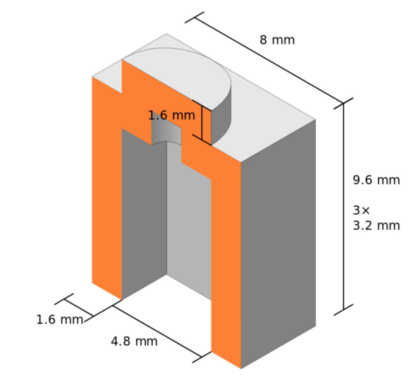
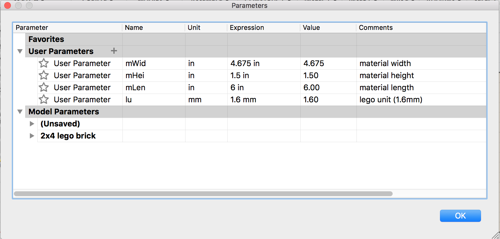
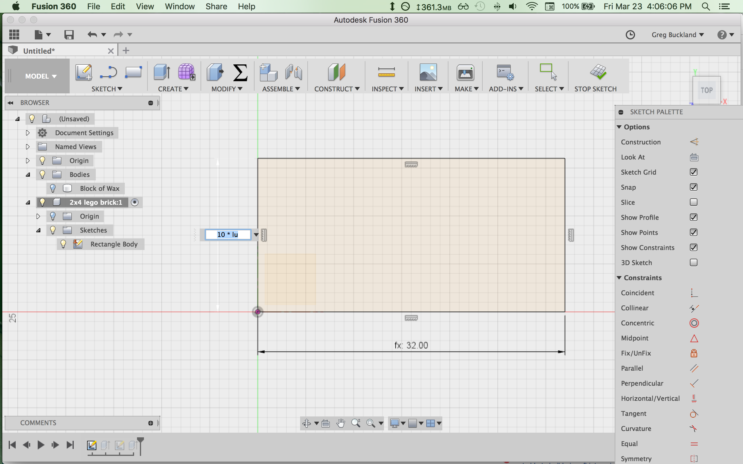
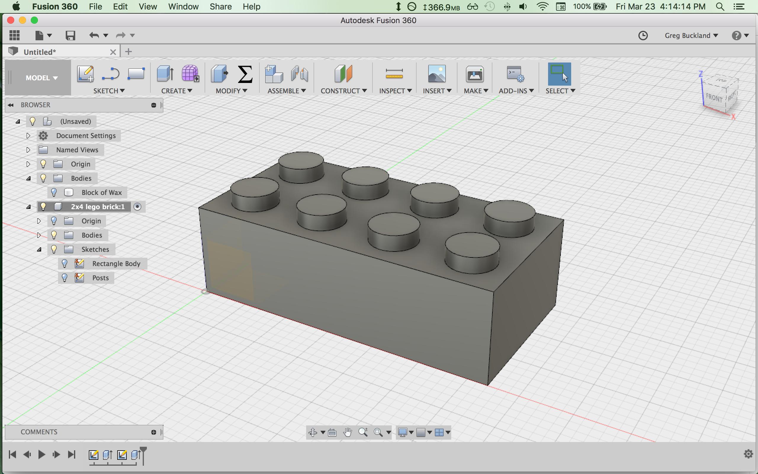
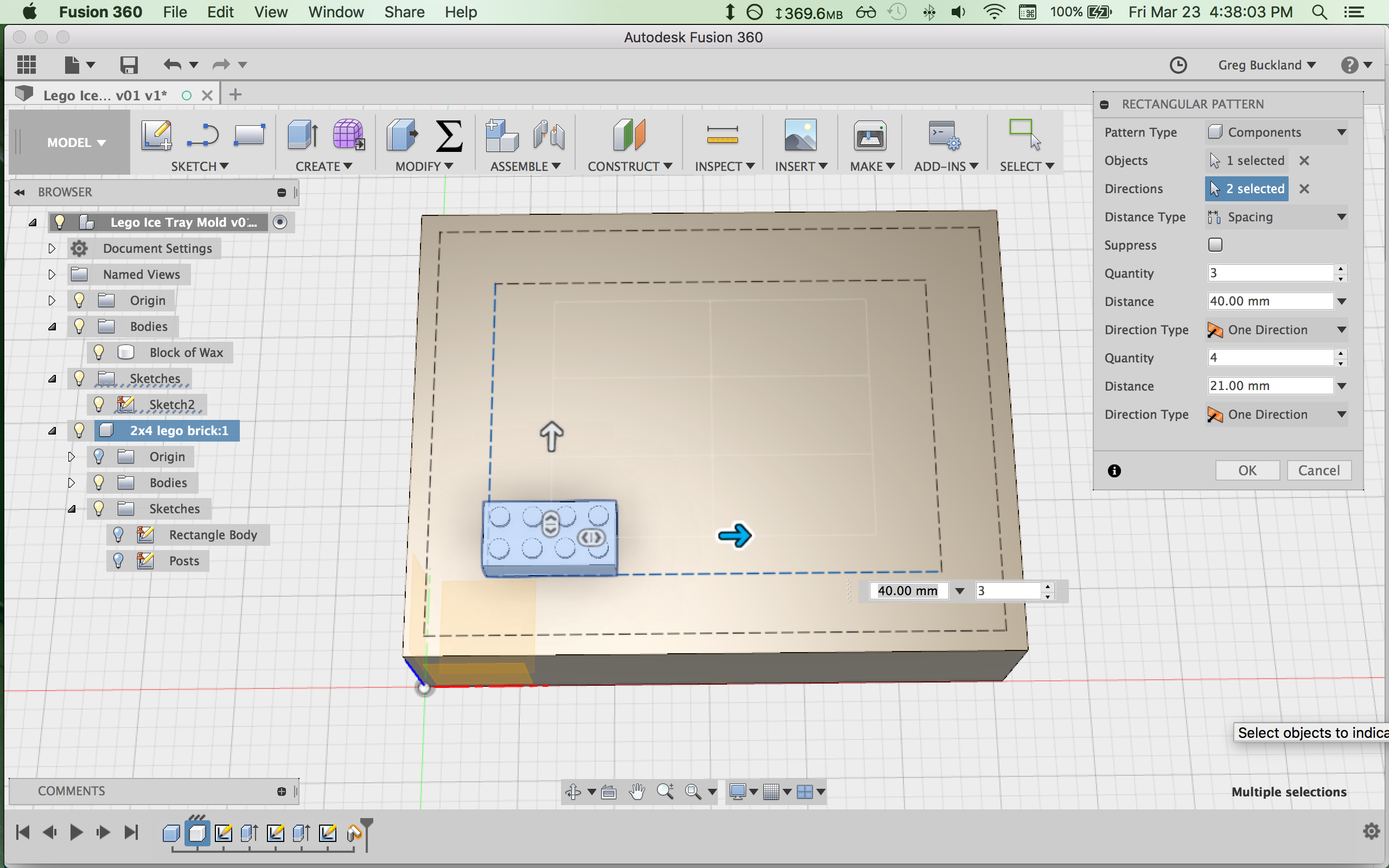
Designing the Counter Mold
With my idea picked out, I began by researching Lego brick dimensions, and worked up a CAD model of a standard 2x4 brick in Fusion 360.
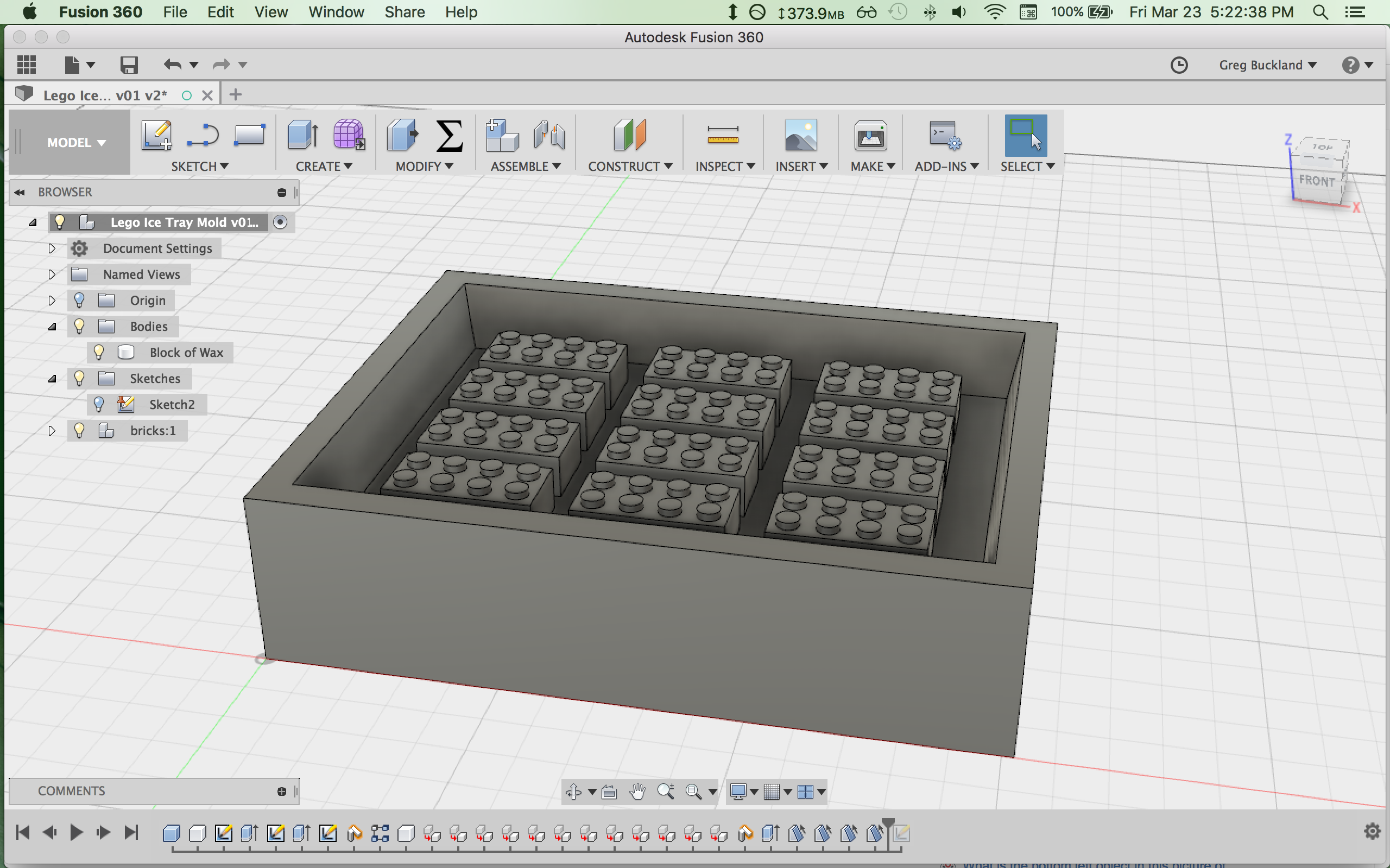
Here's an STL of my counter mold:
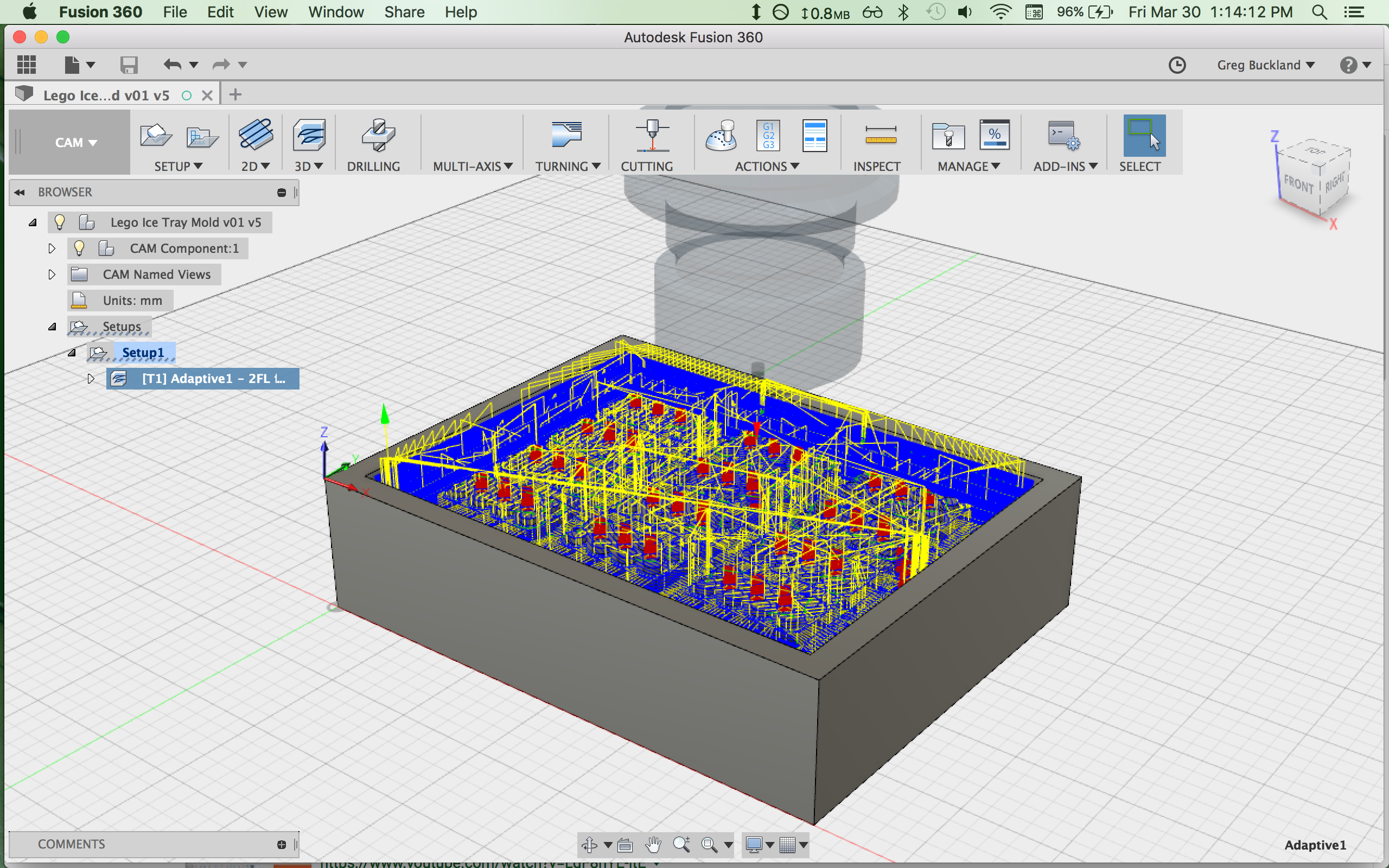
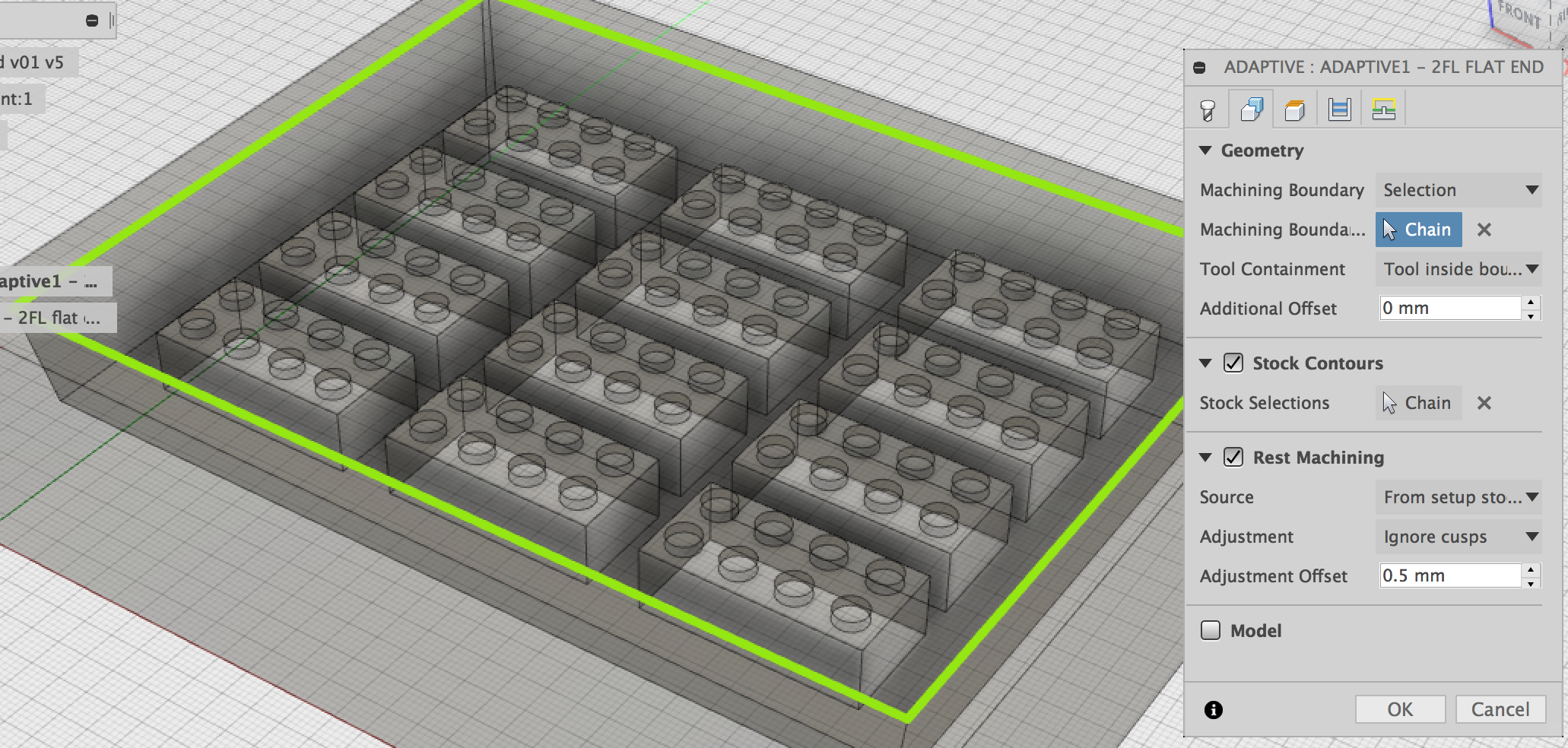
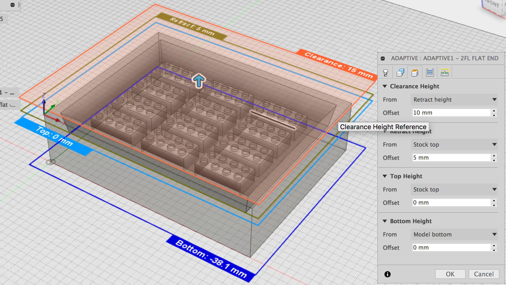
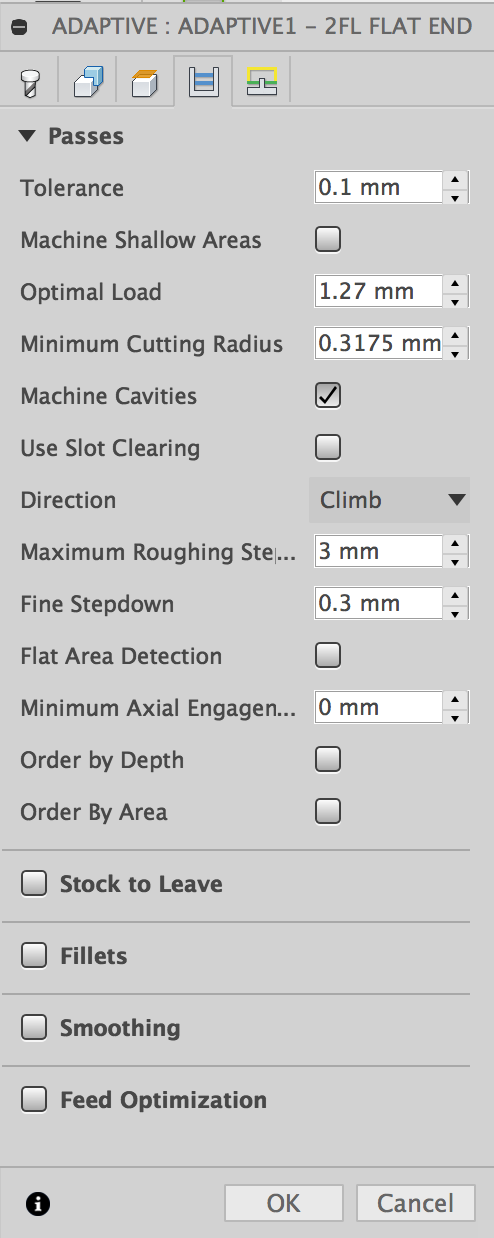
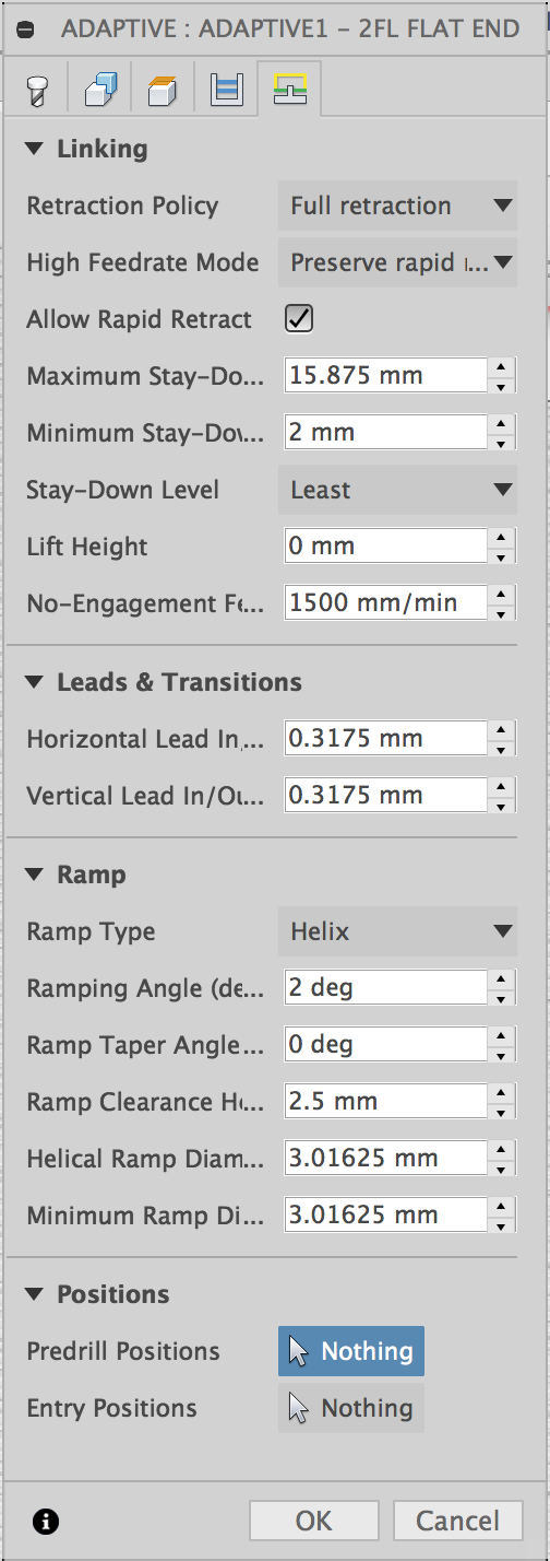
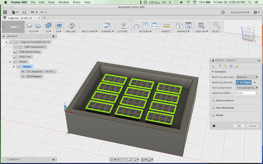
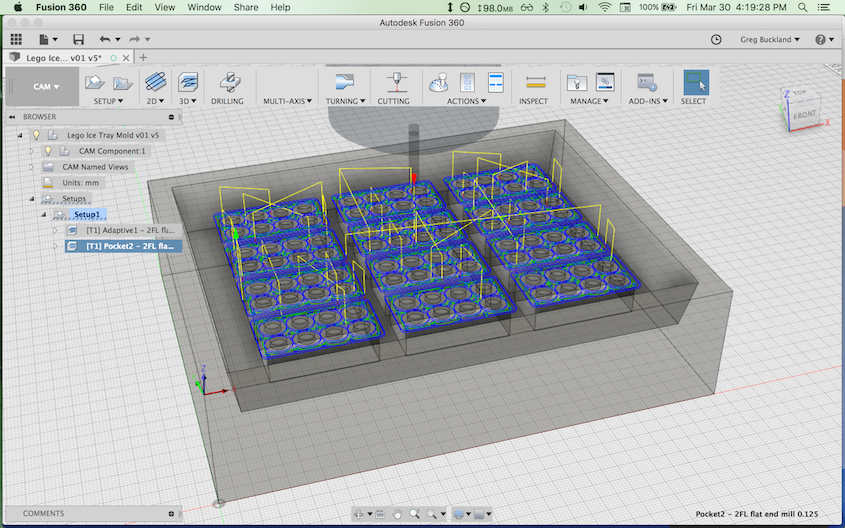
Creating CAM Toolpaths in Fusion 360
I did a bit of googling and found there were not hard and fast guidelines for recommended Feeds and Speeds for milling machinable wax. The closest I came was the Machinable Wax website:
Generally, you'll get the best results by using a cutter design and spindle speed that allows you to effectively clear the chips from the cutting area. Cutters with fewer flutes or teeth and deep gullets are generally better for clearing chips...
(This example was obtained using 1/2" end mill. If you slow down the feed rate then you can reduce the RPM):
- Roughing: Spindle speed 3,000 rpm at ~ 100 inches per minute
- Finishing: Spindle speed 8,000 to 10,000 rpm at ~ 40-100 inches per minute
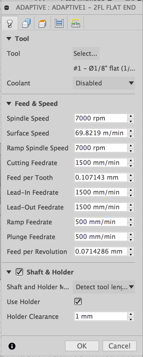
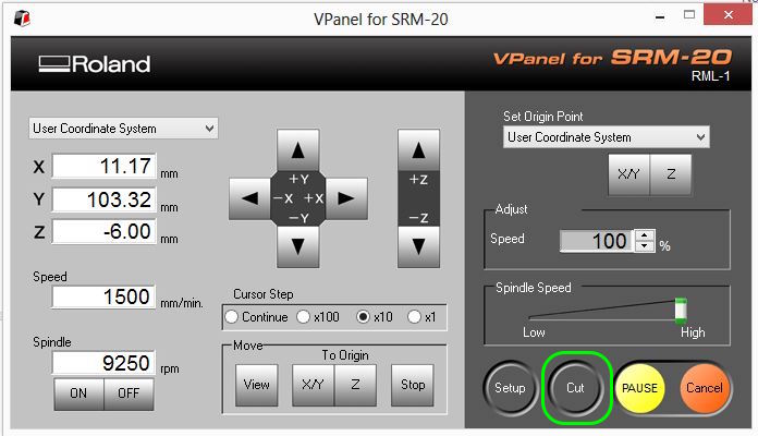
I also found the technical specs of the Roland monoFab SRM-20 on the Roland DGA website, and learned that the maximum spindle speed is listed as 7000 rpm (note: when in operation, Roland's Vpanel software reported actual spindle speeds around 9000 rpm. I'm not sure what this discrepancy is about). In any case, I set the Spindle Speed to 7000 rpm (the putative maximum for the monoFab) and set the Cutting Feedrate to 1500 mm/min (59 in/min - near the middle of the range listed for Machinable Wax).
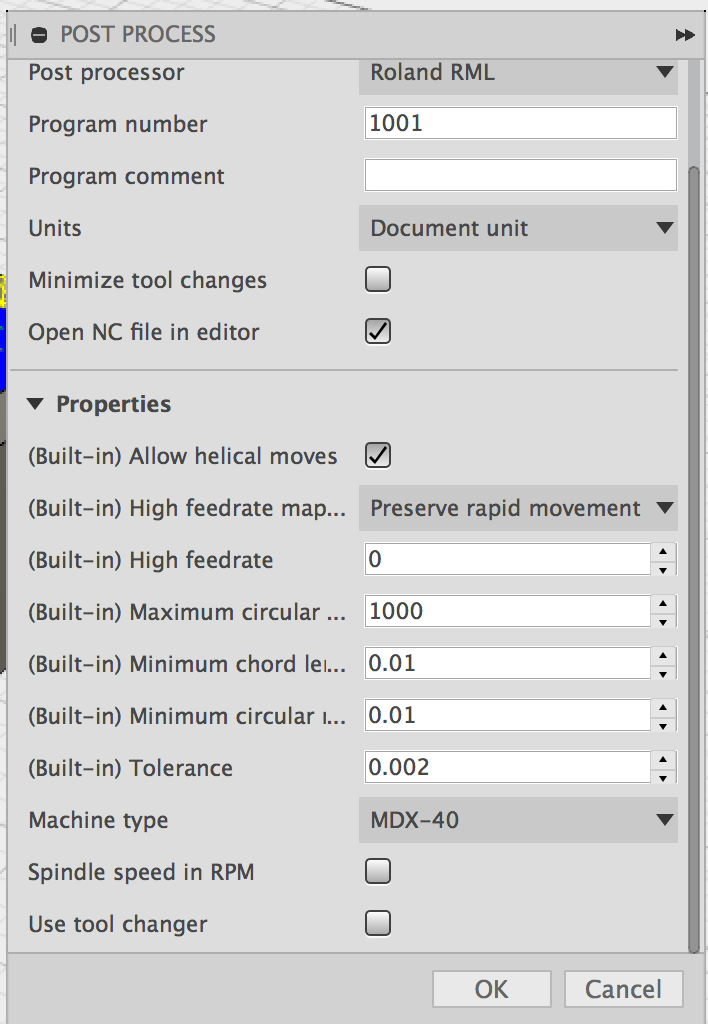
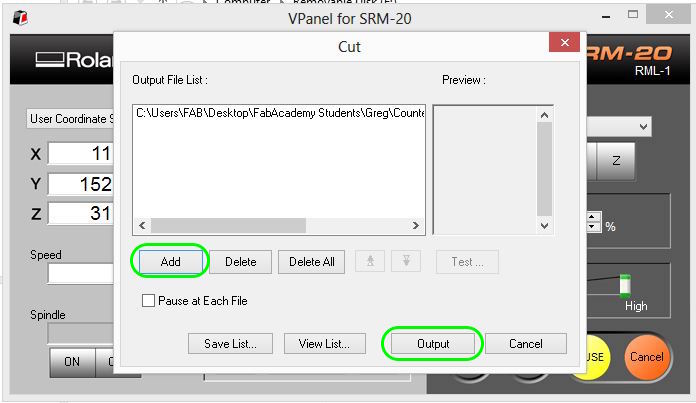
I had done a google search for "Fusion 360 CAM roland SRM-20" and one of the top hits was a FabAcademy page from 2017 from Hashim Al Sakkaf in UAE. He had found that SRM-20 takes essentially the same file format as the MDX-40, so I followed his lead here. I outputted the g-code file as a .prn file.
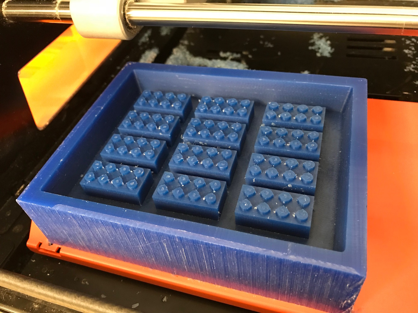
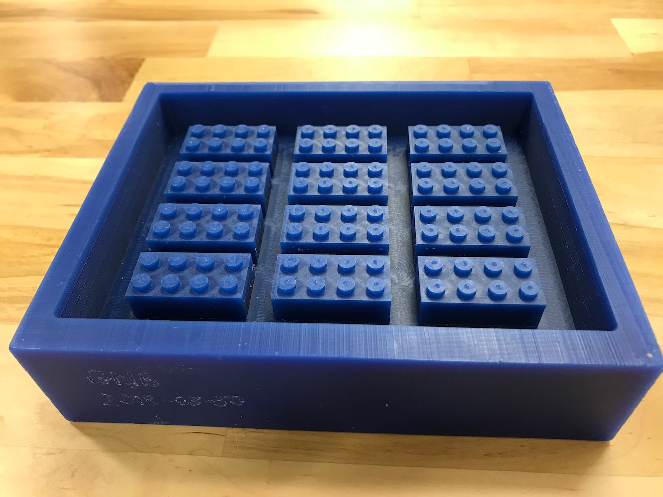
Machining the Counter Mold
18_milling from Greg Buckland on Vimeo.
19_milling_timelapse from Greg Buckland on Vimeo.
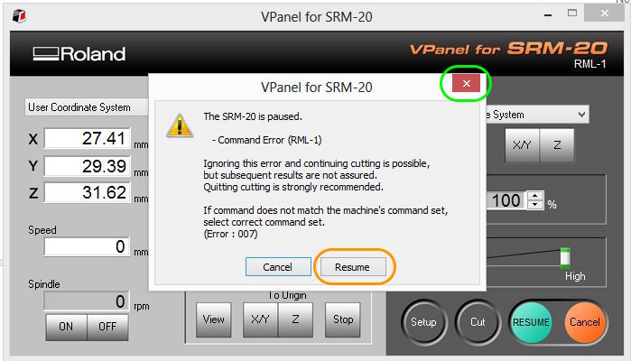
About 25% of the way through my milling, VPanel threw the following error:
The SRM-20 is paused

    - Command Error (RML-1)

Ignoring this error and continuing cutting is possible,
but subsequent results are not assured.
Quitting cutting is strongly recommended.

If command does not match the machine's command set,
select correct command set.
(Error : 007)
My hunch is that this error comes from using the MDX-40 as the machine for post-processing. There is probably some command in the gcode that the SRM-20 doesn't like. It made me nervous, but I also new I didn't really have an option to "select the correct command set" since Fusion 360 didn't have a command set for SRM-20. At first I clicked "Resume" but the error came back up. I clicked "Resume" 10 or 20 more times and always the error came back. Finally, I clicked the red "X" in the upper right to close the window, and this did the trick. The SRM-20 started up again and proceeded to finish the cut without problems. Whew!
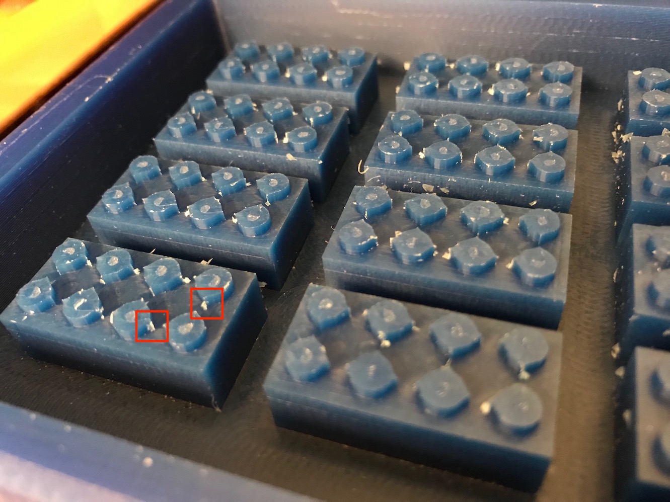
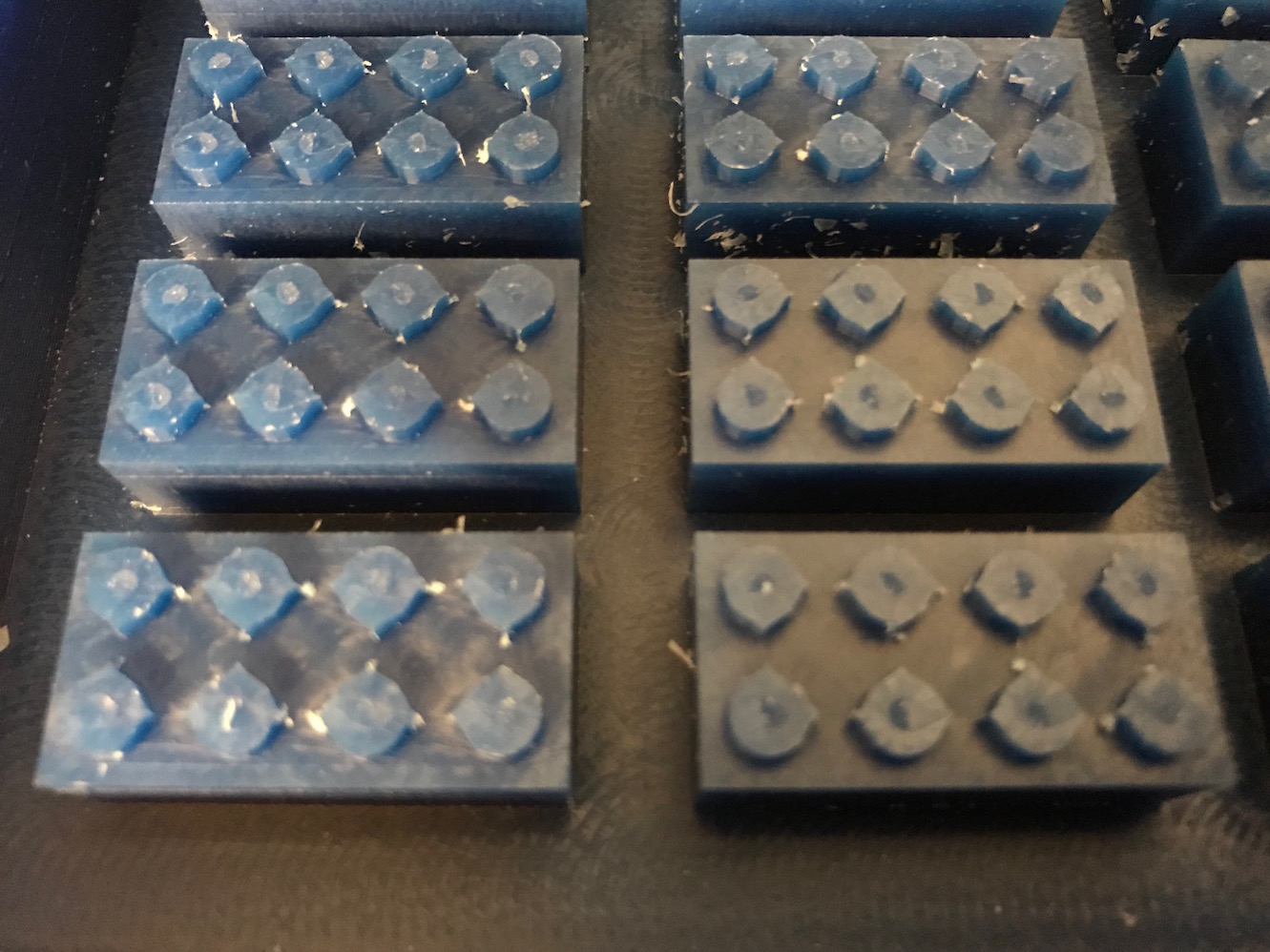
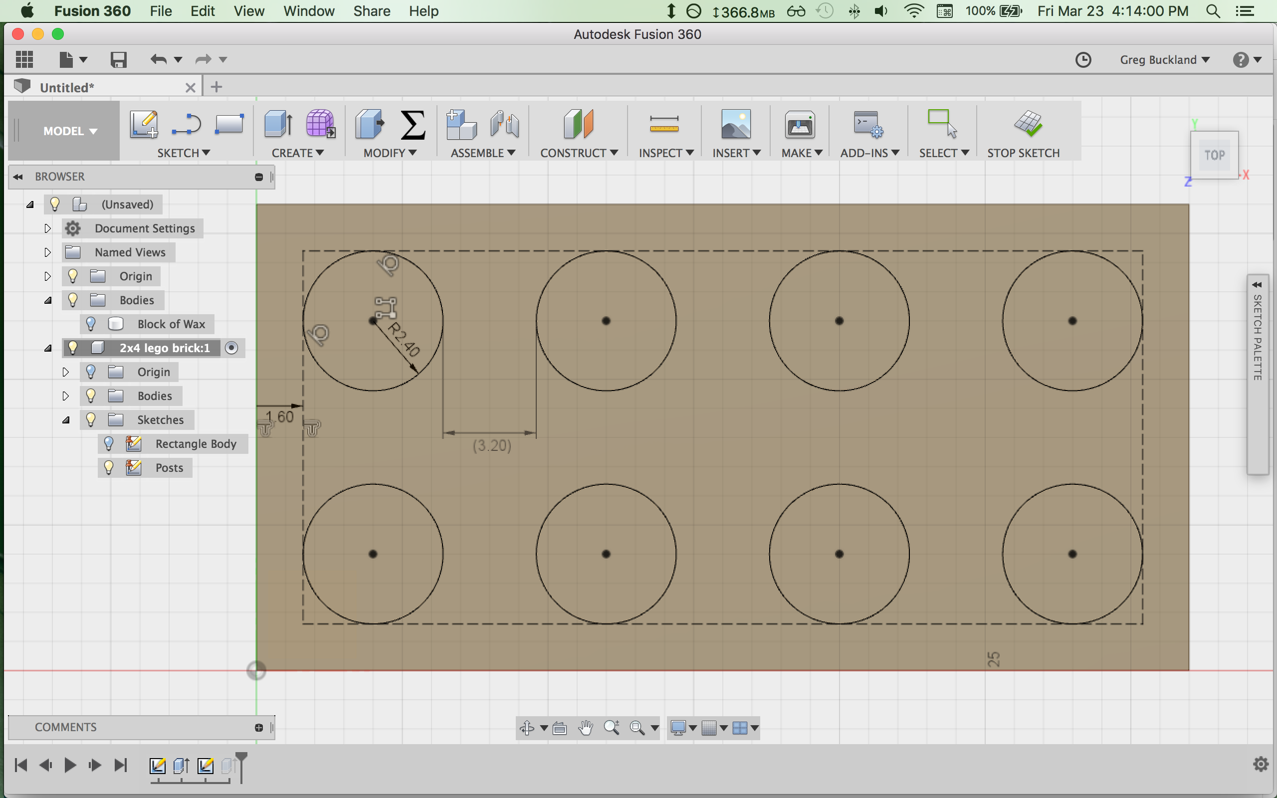
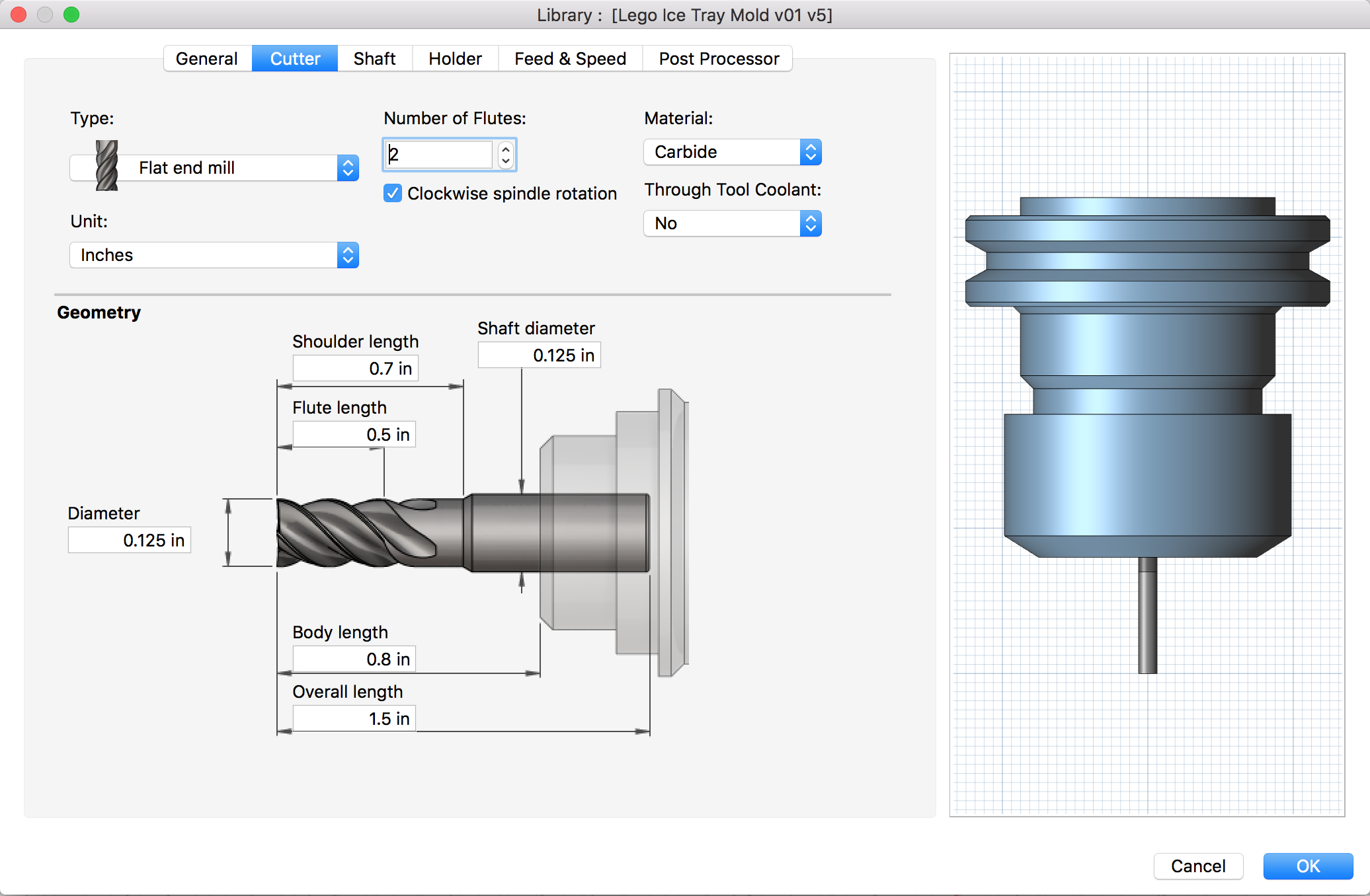
I realized that the tool was not passing between the posts and so it was creating these little artifacts like 4-pointed stars around each post. I knew that the tool diameter was 3.17mm (0.125") and that the clearance between the posts was 3.20mm (2 'lego units') and so the tool should be able to clear that space and go all the way around and between the posts. What I came to realize was that back in the Passes setting when I was creating my toolpaths, I had left the Tolerance at the default 0.1mm. This meant that the toolpath added 0.1mm to each post, meaning the perceived distance between them was 3.0mm, and the machine would not pass the 3.17mm tool between them. D'oh!
Luckily, I had not removed the workpiece from the monoFab bed, and so I still had a good "register". I went back to Fusion 360's CAM workspace and created a new toolpath to clean up around the posts.
26_finishing from Greg Buckland on Vimeo.
Casting the Mold
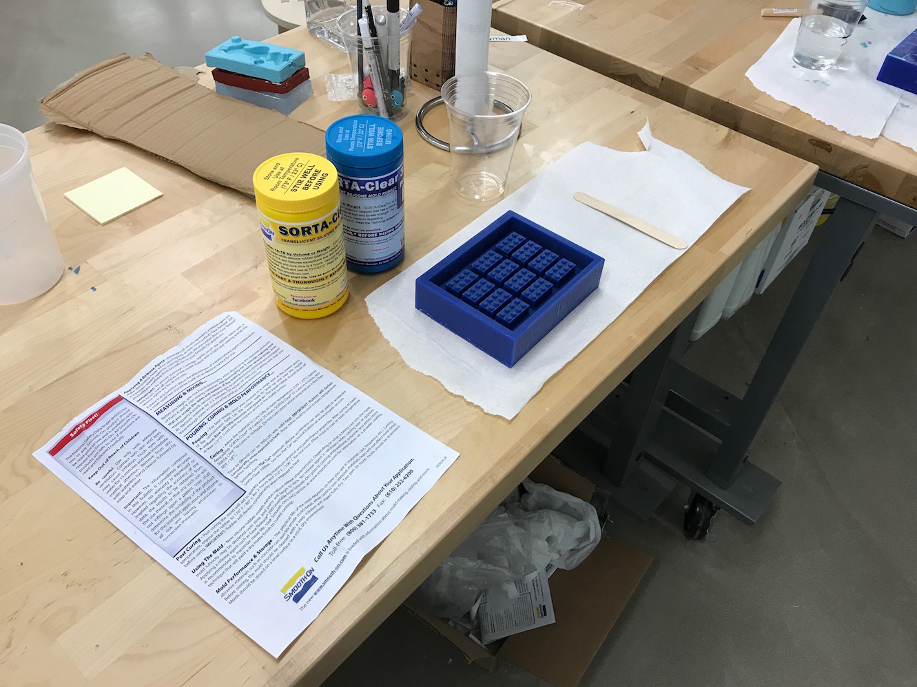
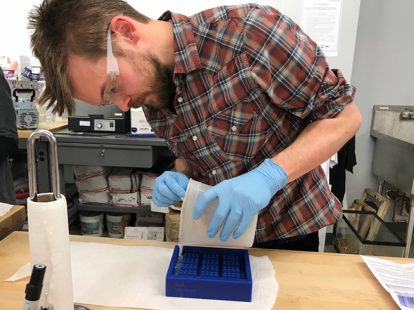
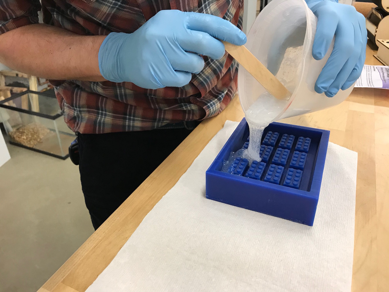
Now that the milling was complete, I got ready to cast my mold in the counter mold. I wanted the final mold to be food safe, and so I chose Smooth-On SORTA-Clear 37, which we had in the lab.
Back in Fusion 360, I made a negative of the countemold to help me calculate the volume of silicone I would need. I just made a second block of material and did a boolean subtract with the counter mold:
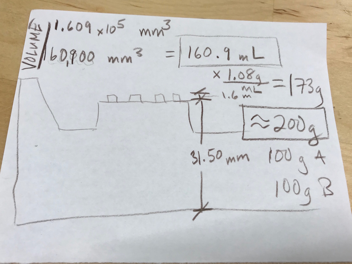
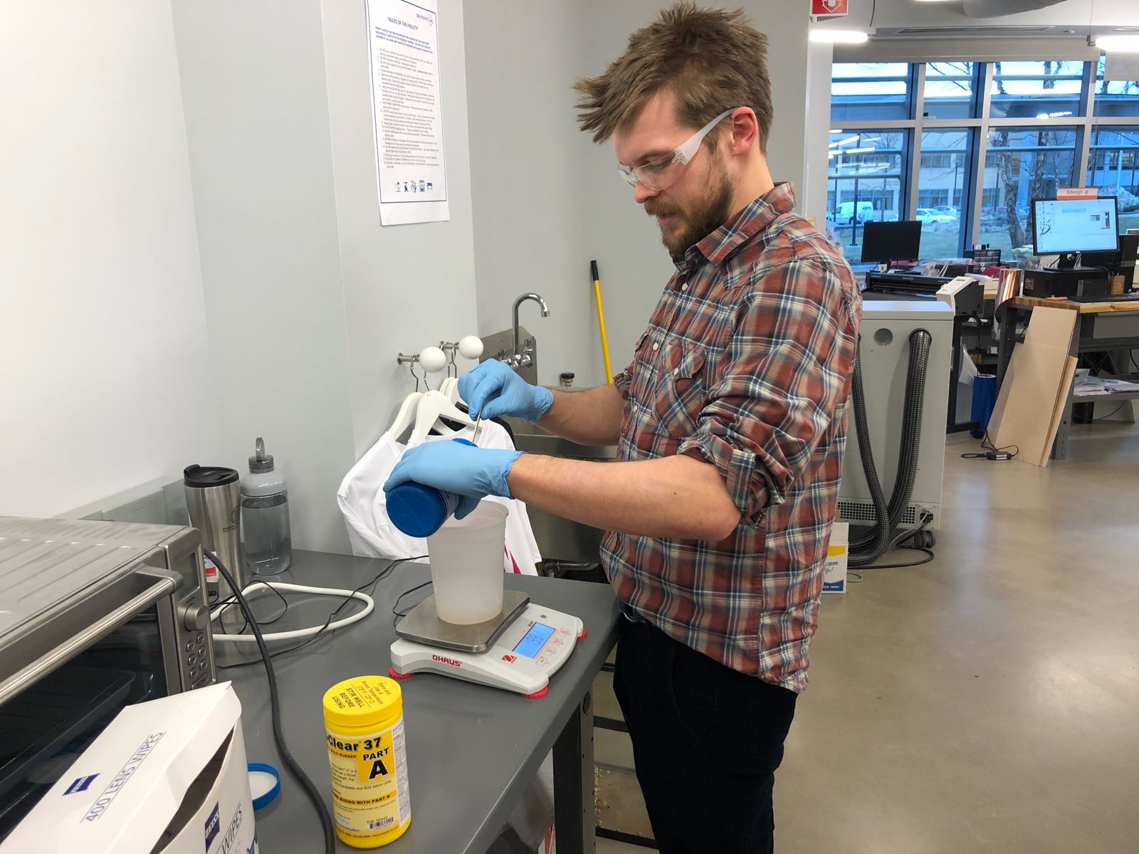
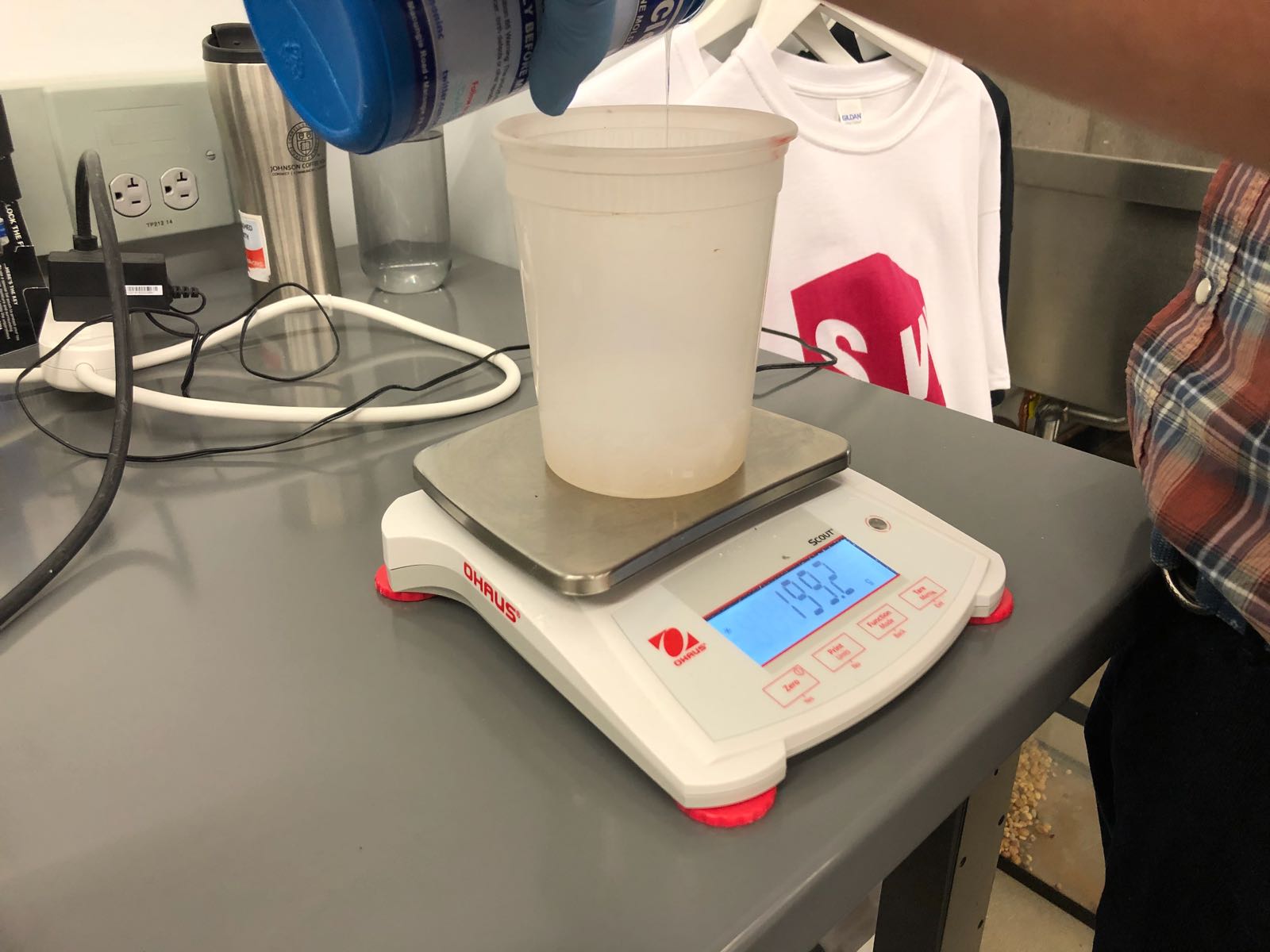
By going to Right-Click > Properties on the negative space object, Fusion 360 reported that the object's volume was 1.609 X 105 mm3, or 160.9mL. The data sheet for SORTA Clear 37 told me that it was 1.08g/cc and a cc and a mL are the same, so some quick math told me I'd need 160.9 x 1.08 = 173g of silicone. To account for some lost material in mixing and pouring, I rounded up by about 15% to 200g, indicating 100g of Part A and 100g of Part B.
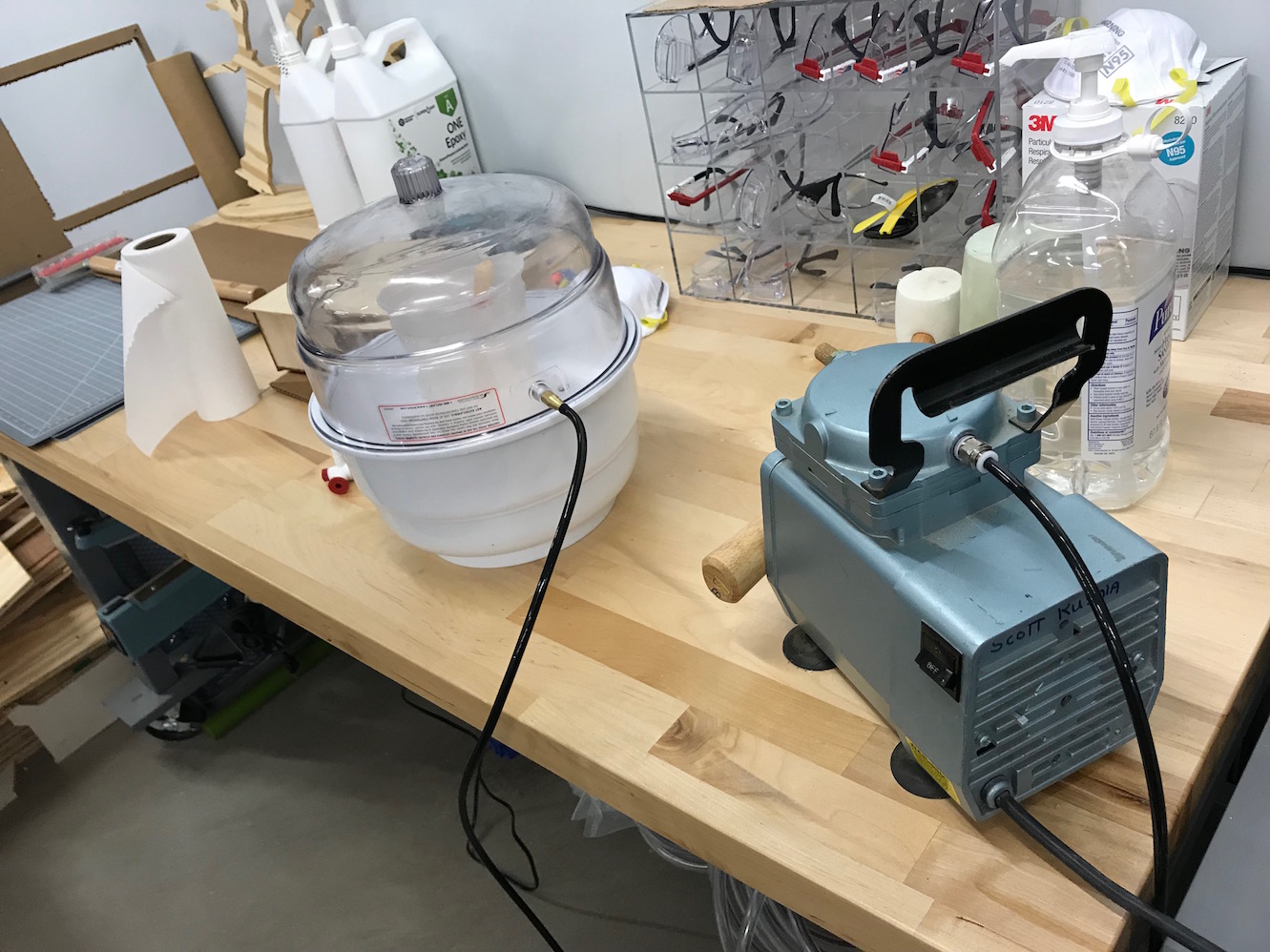
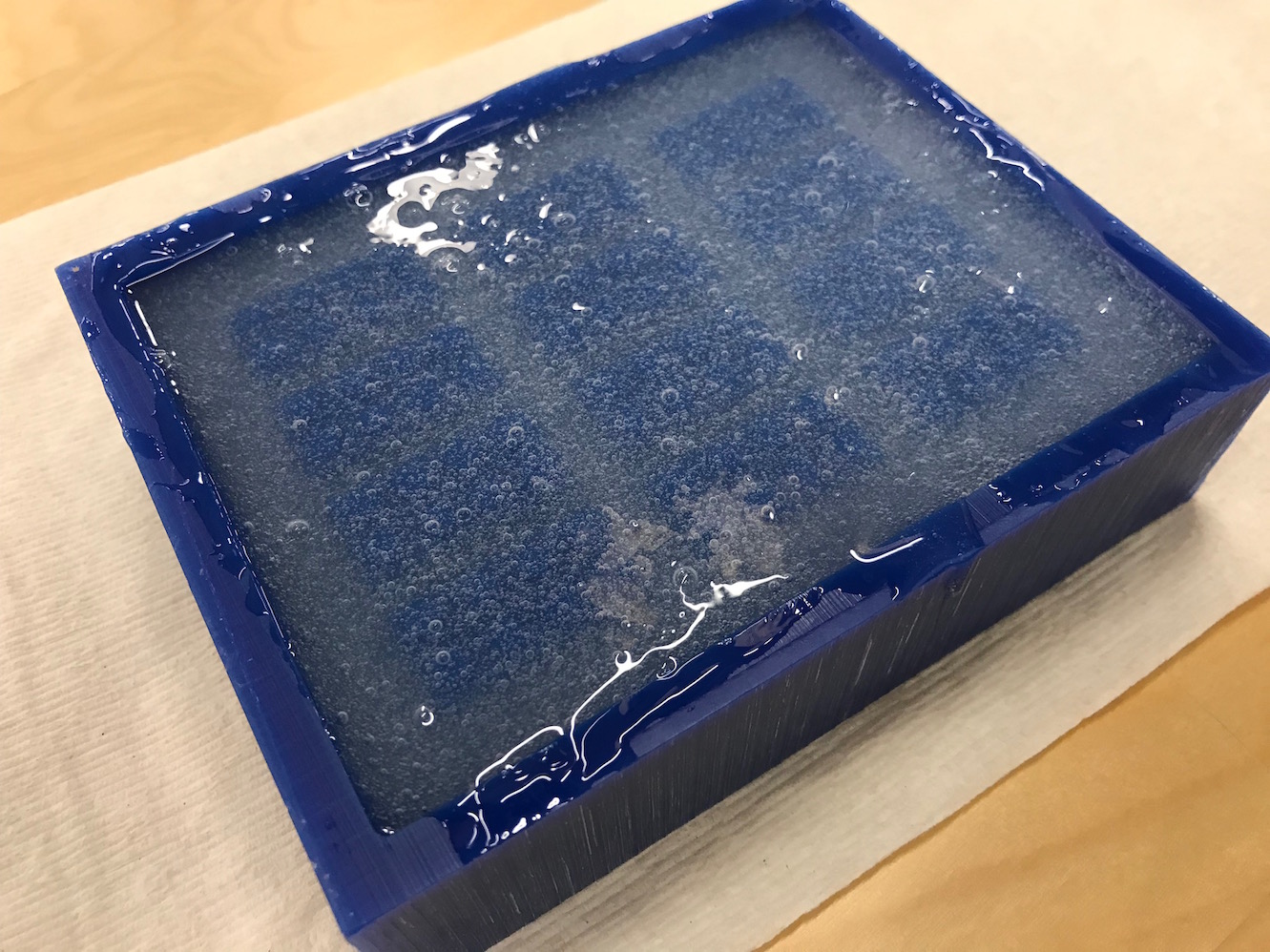
There were still quite a few bubbles in the material, so I placed the filled countermold into the vacuum chamber for degassing as well:
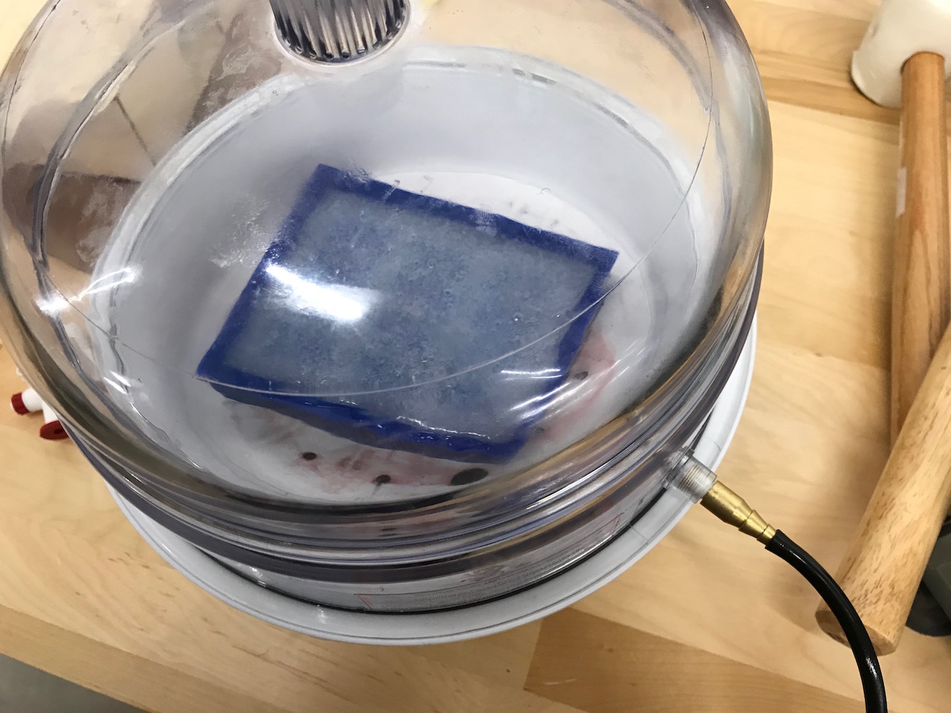
I ran the vacuum chamber 3 times total, attempting to remove as many bubbles as possible, or at least to pull them away from the surface of the mold to avoid bubbles in the final product.
Demolding and Post Curing
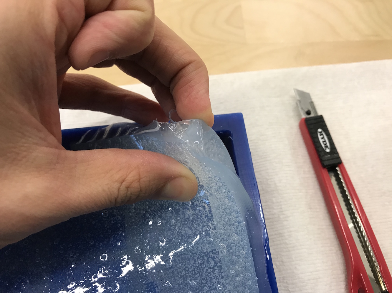
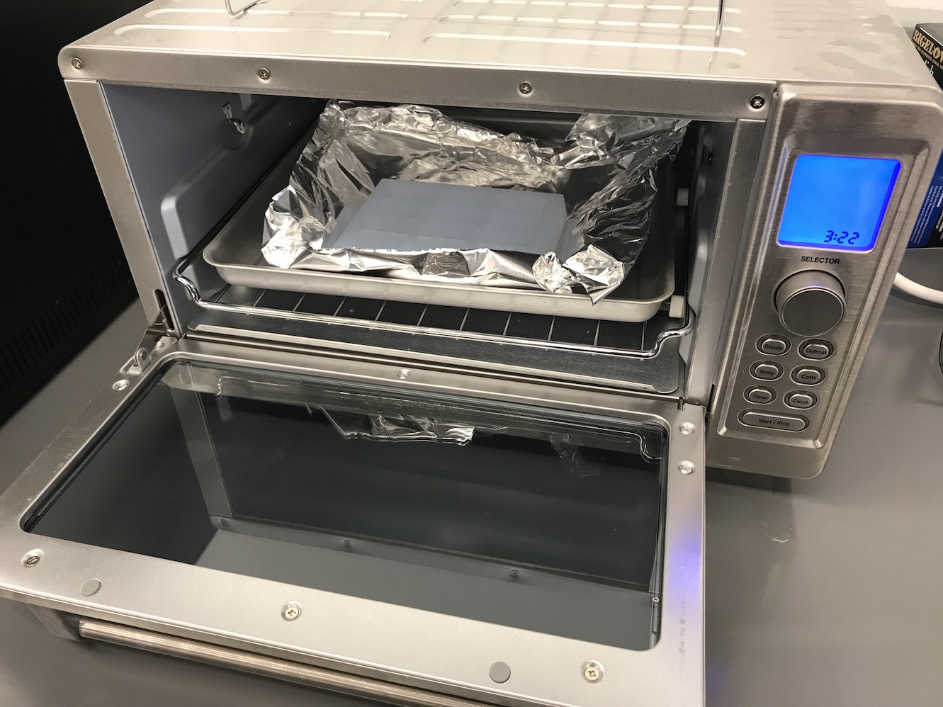
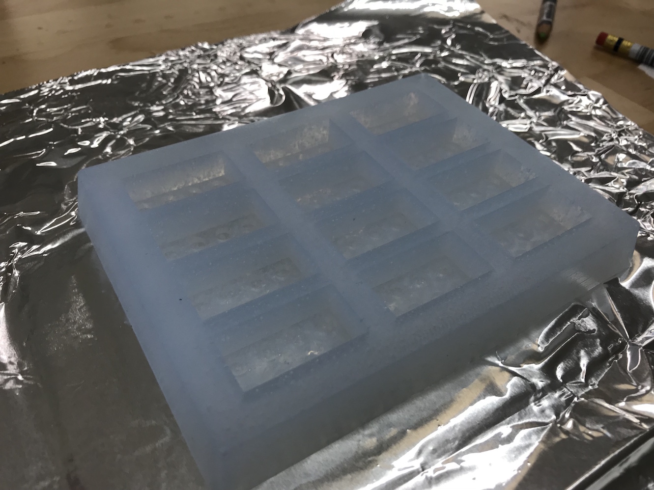
Final Results
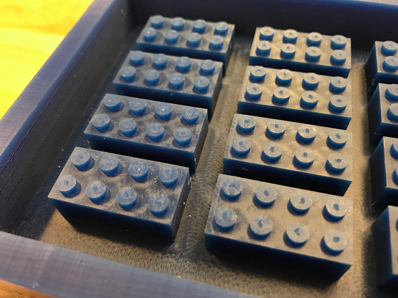
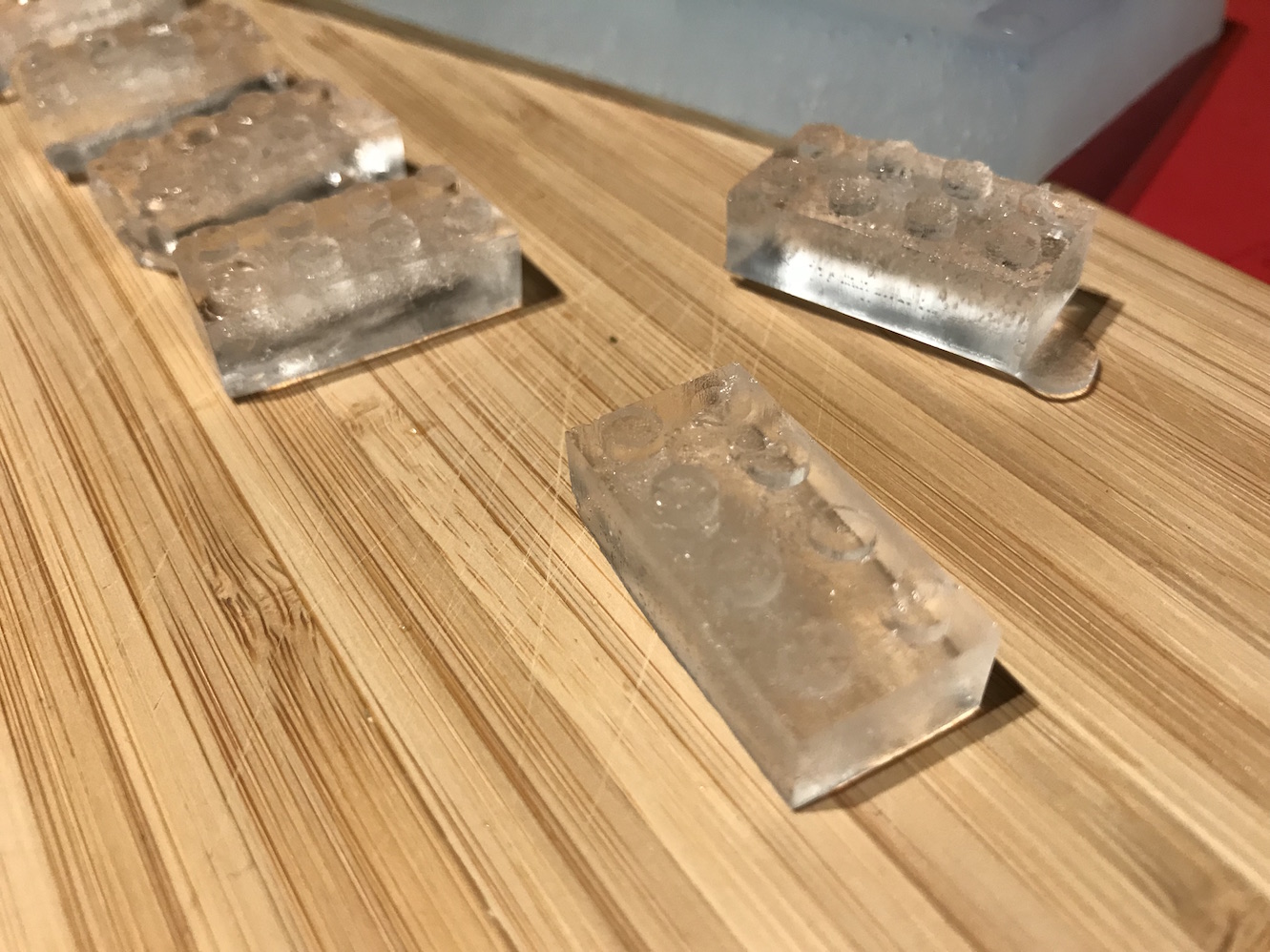
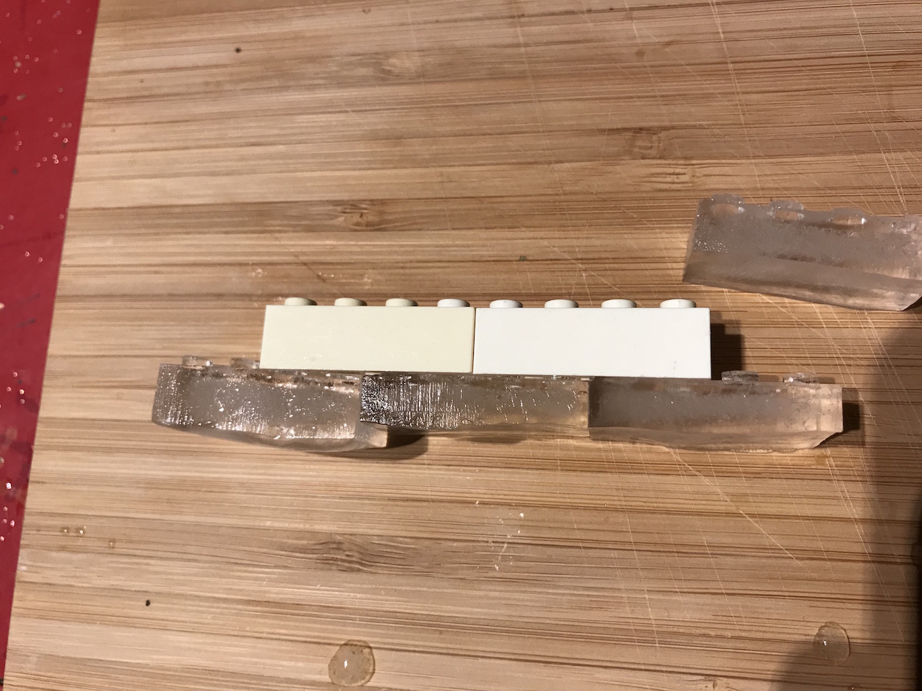
I carefully washed the mold with dish soap and water to clean any remaining dust, wax, etc from it, and poured water into the mold to create my ice cubes. A few hours later, I had lego brick ice cubes!
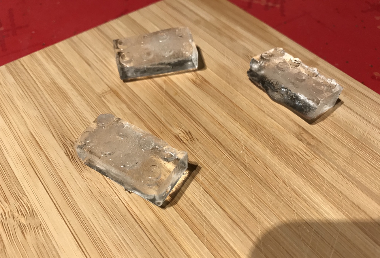
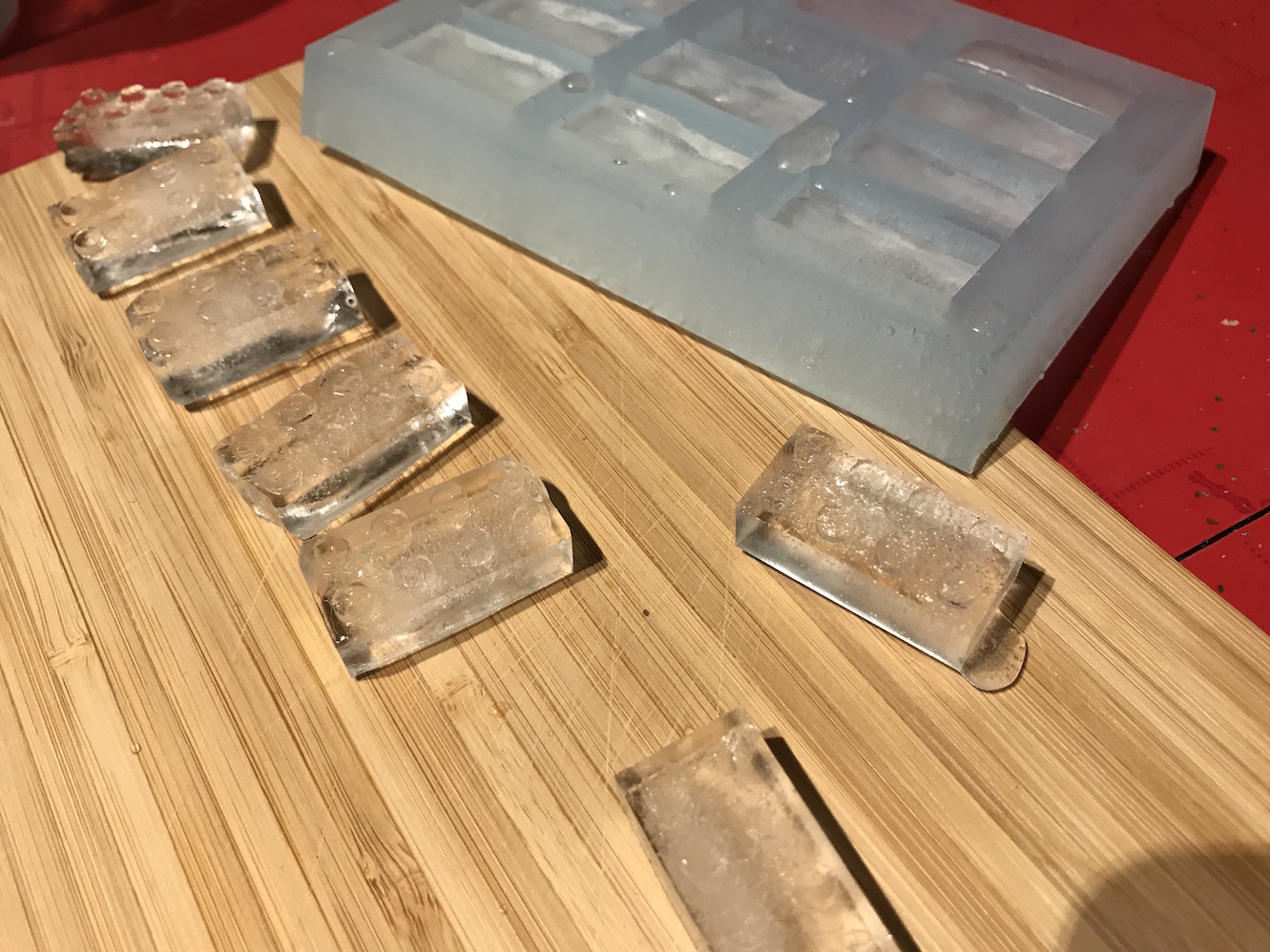
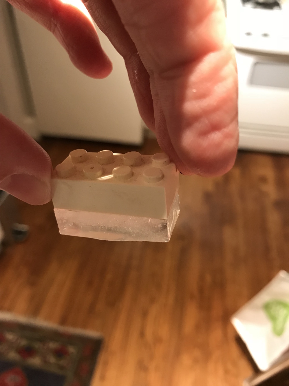
If there's anything more I'd like to learn about with this it's 1) doing multi-part molds and 2) figuring out how to eliminate bubbles in the silicone more effectively. There definitely were tons of bubbles left in my silicone mold. It didn't affect the quality of the final ice cubes much, but it's something I'd like to learn and improve none the less.
Design Files
Counter mold (.STL file)
Mold negative space (.STL file)
Lego Ice Tray mold and Counter Mold (.F3D file)