Computer-aided Design
Have you:
[x] Modelled experimental objects/part of a possible project in 2D and 3D software
[x] Shown how you did it with words/images/screenshots
[x] Included your original design files
2D design is accomplished in raster formats through GIMP. I use this as an alternative to PhotoShop since it is free to use. Raster means that the files that contain the images are all pixels. I usually use JPG, which is good for photos or textures which do not need very high resolutions.
I also use PNG, which is good for files that have text or geometry that requires a higher resolution. I can take screenshots as well, which in Mac OS X defaults to PNG. Since these files usually have text, I use ImageMagick to convert the PNGs to a standard size and specify a quality of no less than 90%.
Inkscape saves 2D design files as SVG. I can also export the files to a PNG and if needed use ImageMagick for processing.
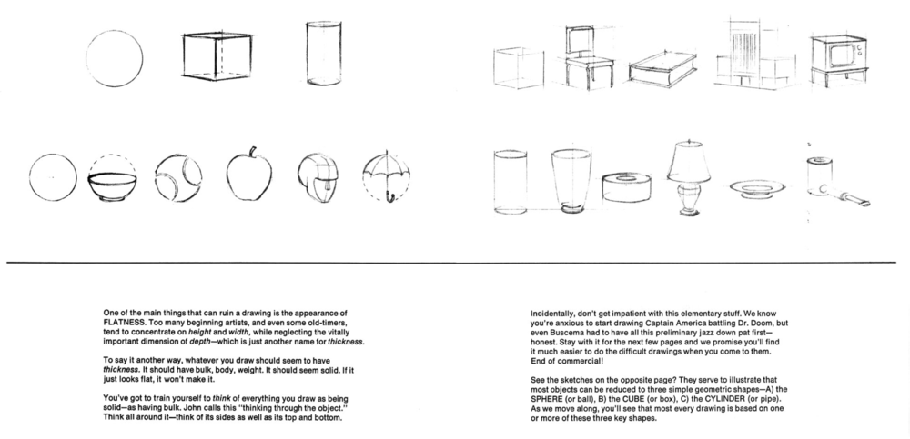
One book that has really helped me design is Drawing Comics the Marvel Way. I had a copy when I was a teenager and return to it whenever I need a reminder of the basic, especially when working with new tools. It’s also helpful in this context as many of the science fiction visuals such a vehicles, weapons, and computers are really compelling when designed by Jack Kirby or John Buscema.
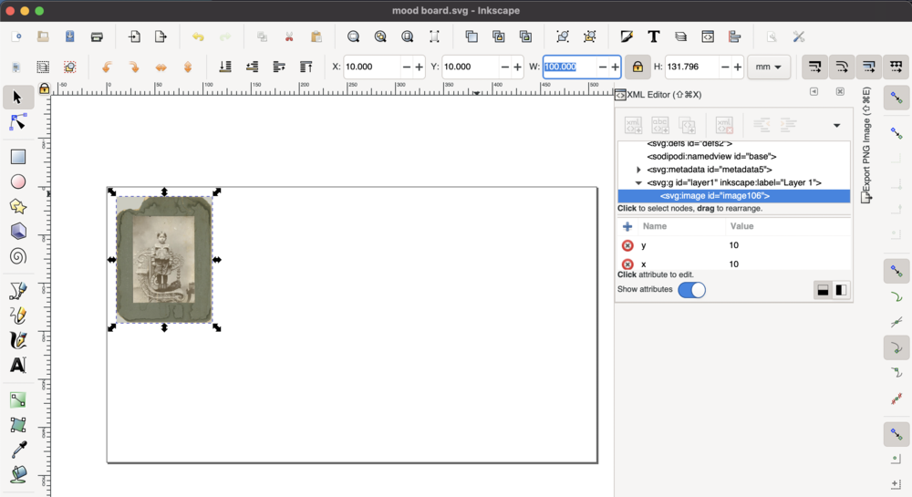
To get started designing, I can open Inkscape and create a mood or vision board just to get a flavor of what I would like to make. I set the document properties to 1920 x 1080 pixels which is a good resolution for presentations. Next, I can search for some ideas online to help build out the idea.
Link to design file
I will search Creative Commons for images to use:
I searched for chair to pull some images. Since this is for ideation, I don’t need very high resolution images. I can import my images. I can then position and scale the images in the toolbar. By clicking on the lock icon, I can be sure that images are scaled proportionately. The TAB key help to select individual elements of the document. I can also turn on the XML Editor to understand the code of the SVG that I am creating.
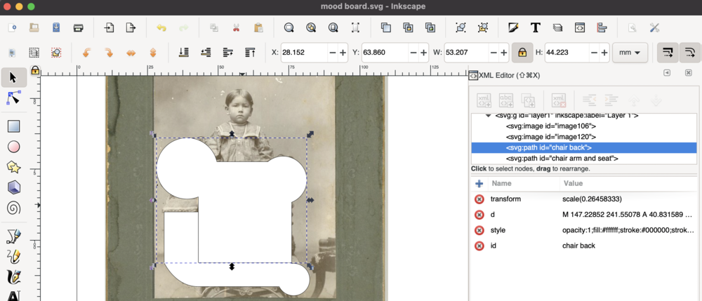
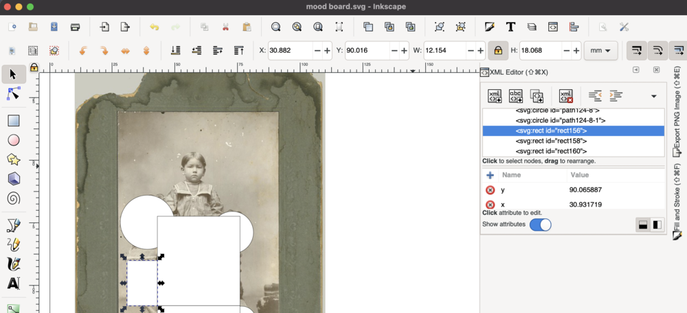
One I have the pictures laid out on the board, I can start planning geometry by blocking out where primitives are in the design. In the case of 2D design, I can use circles, squares/rectangles, and triangles. I plan out the primitives, then I convert the shapes into paths. I can add nodes to the paths and perform boolean operations. I can also refer back to the XML editor and label elements as I want.
Going from 2D to 3D, I can start a design in FreeCAD. I use the application with a trackpad which takes some time to get used to to learn how to rotate the window’s camera and how to also pan it around whatever is being modeled.
Link to design file
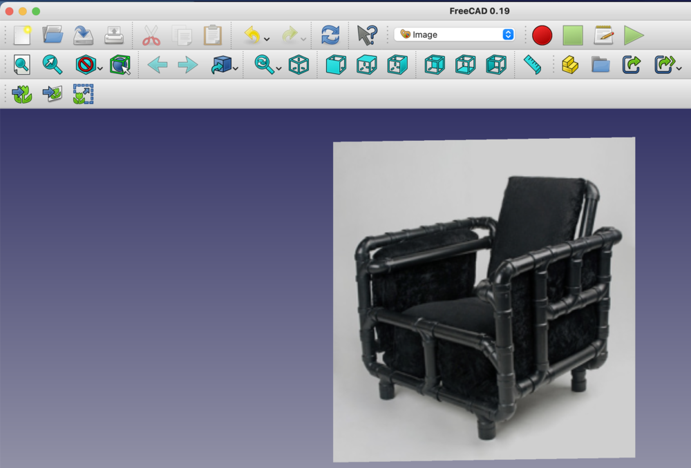
FreeCAD has several workbenches to navigate. I start by adding the reference image to my document. I do this by going to the Image workbench and adding an image plane. I can add a spreadsheet to start giving the model some design constraints. I can also reference the constraints from other workbenches.
I add a cube to help define the overall dimensions of the object. I can then start working on one of the parts of the overall model. It’s good to get as close as possible to real life dimensions. The primitives that I can use in this case are cubes, cylinders, spheres, or cones.
Once I have a specific part ready I can export that to an STL from an option in the File menu. The STL can then be opened by Blender or Rhino. I can also further return to Inkscape and take my 2D design and save the SVG to import to Blender or Rhino. I’m going to use Rhino first, since Blender is best for animation and simulation.
In Rhino, I import the SVGs. I then enter the command Make2D to be sure that the geometry that I import is a closed curve. Rhino primarily uses NURBS to model geometry. It can convert to polygonal meshes. The primary difference I found was explained this way, “For polygon modeling it calculates polygons, which are flat planes that comprise a 3D shape (the way that a cube is made out of 6 squares for example). NURBS calculates the mesh as splines between points, which can make curves out of a single section of geometry. NURBS (which is shorthand for Non-Uniform Rational B-splines) uses complex mathematics to calculate the surface of a model. This means that it is far better suited for models where a high degree of accuracy is needed.”https://conceptartempire.com/polygonal-vs-nurbs/
Link to design fileI extruded the geometry to dimensions that I thought would work. I also added fillets to the edges of the geometry to help style the parts.
In Blender, I import the STLs. I then manipulate them to create a character model of my project. I can return to this application to creature and armature to further animate the model.
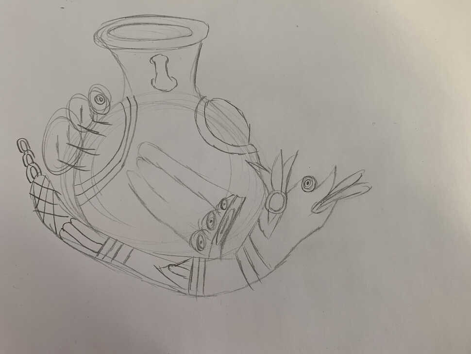
Link to design fileOriginal sketch
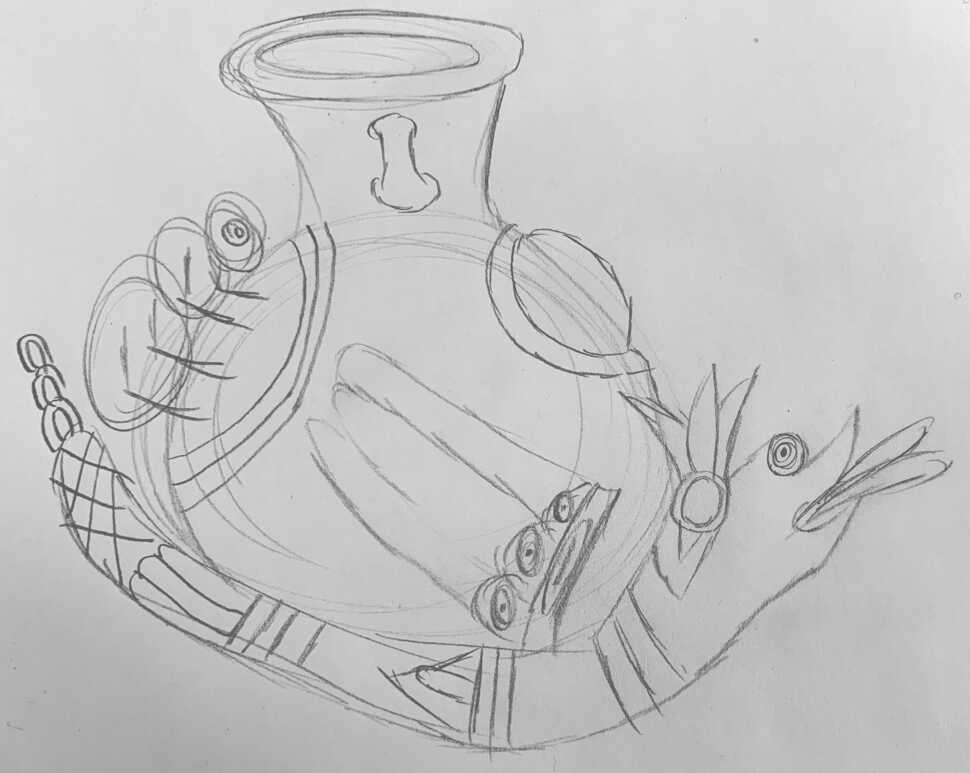
Correcting with GIMP
Output from GIMP
Vectorizing with Inkscape
Output from Inkscape
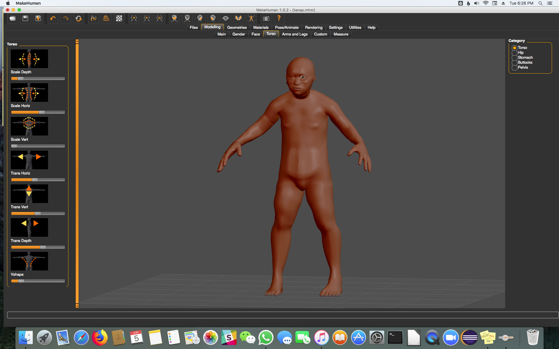
Final Project 2018 - Tanap, the Medicine Keeper
Testing Model with MakeHuman