WEEK 10
Input Devices
Assignment:
- Measure something: add a sensor to a microcontroller board that you have designed and read it
Software(s):
- Arduino
- Adobe Illustrator
Skill(s):
- Electric Design|
- Electrical Prototyping
- Programming
Week 10 assignment was a continuation of Week 8’s (http://archive.fabacademy.org/2018/labs/fablabdassault/students/oyedotun-ajweole/exercise08.html) assignment. At the end of Week 8‘s assignment I was able to successfully make a board that read temperature but I also ran into a few problems with the board. After a few trials and failures I realized the Attiny44 does not have enough memory for the functions in my final project. I needed to do some redesigning of my board at this point.
This is where Week 10 begins
Off of the recommendation of Luciano, I decided to switch to using the “Barduino” as my main board for my final project. The Barduino has uses an Atmega328 as its microcontroller, which has more than enough memory and power for the functions I am looking for. In addition to the Barduino, I plan to make a few peripheral boards to work in conjunction with the Barduino. At the moment I am imagining three peripheral boards; two for the inside and outside thermistors and one for the RGB LED.
SHEMATIC DESIGN
Creating the Barduino was straightforward. I was lucky that there was a well-documented tutorial (http://fabacademy.org/archives/content/projects/barduino/index.html) on how to build and program the board. Following this tutorial I downloaded the EAGLE schematic and layout files and exported the layout for milling.
( Quick Note: I decided not to add or change the layout of the components on the board because I would add all the necessary parts on to separate boards.)


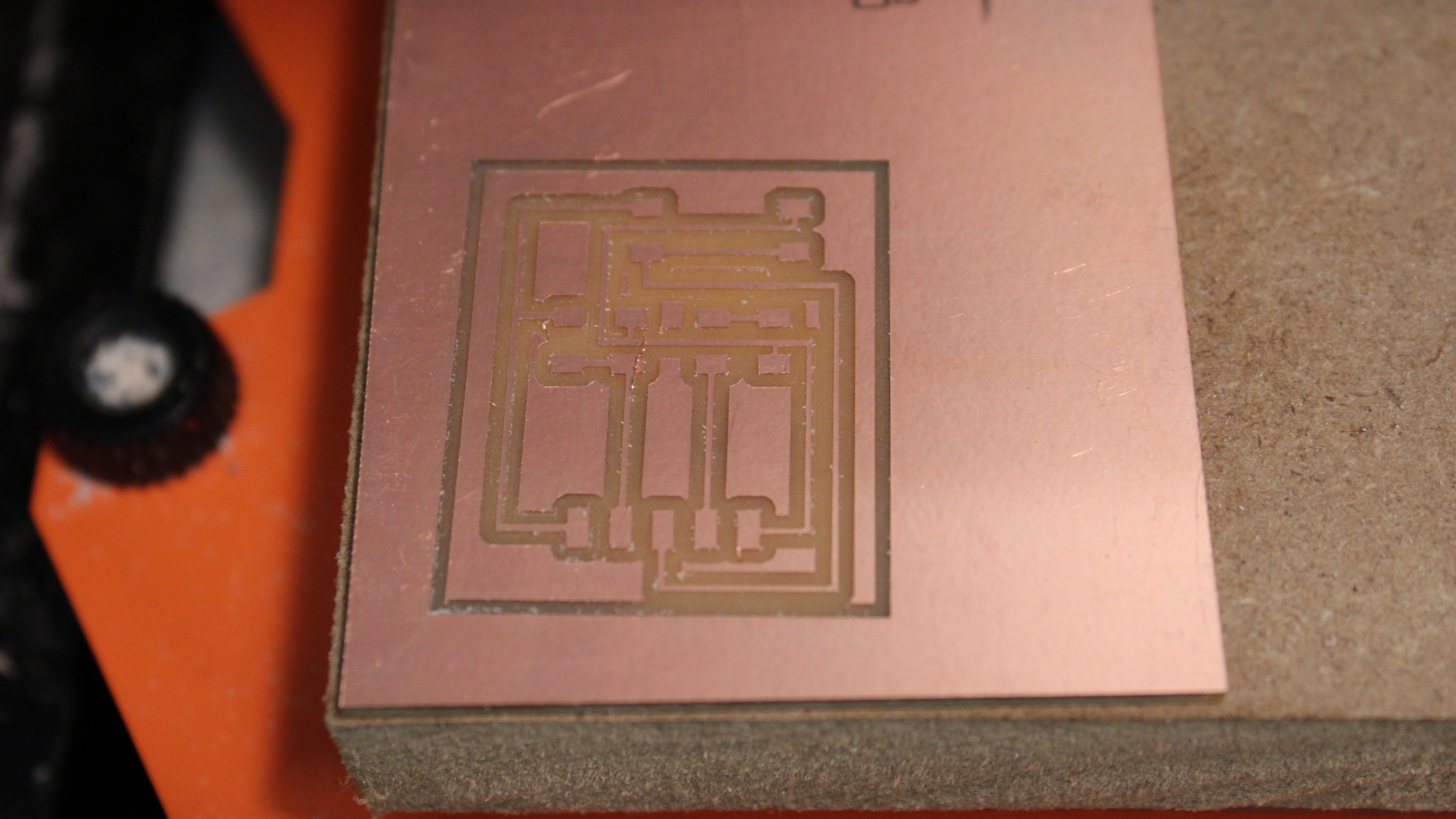
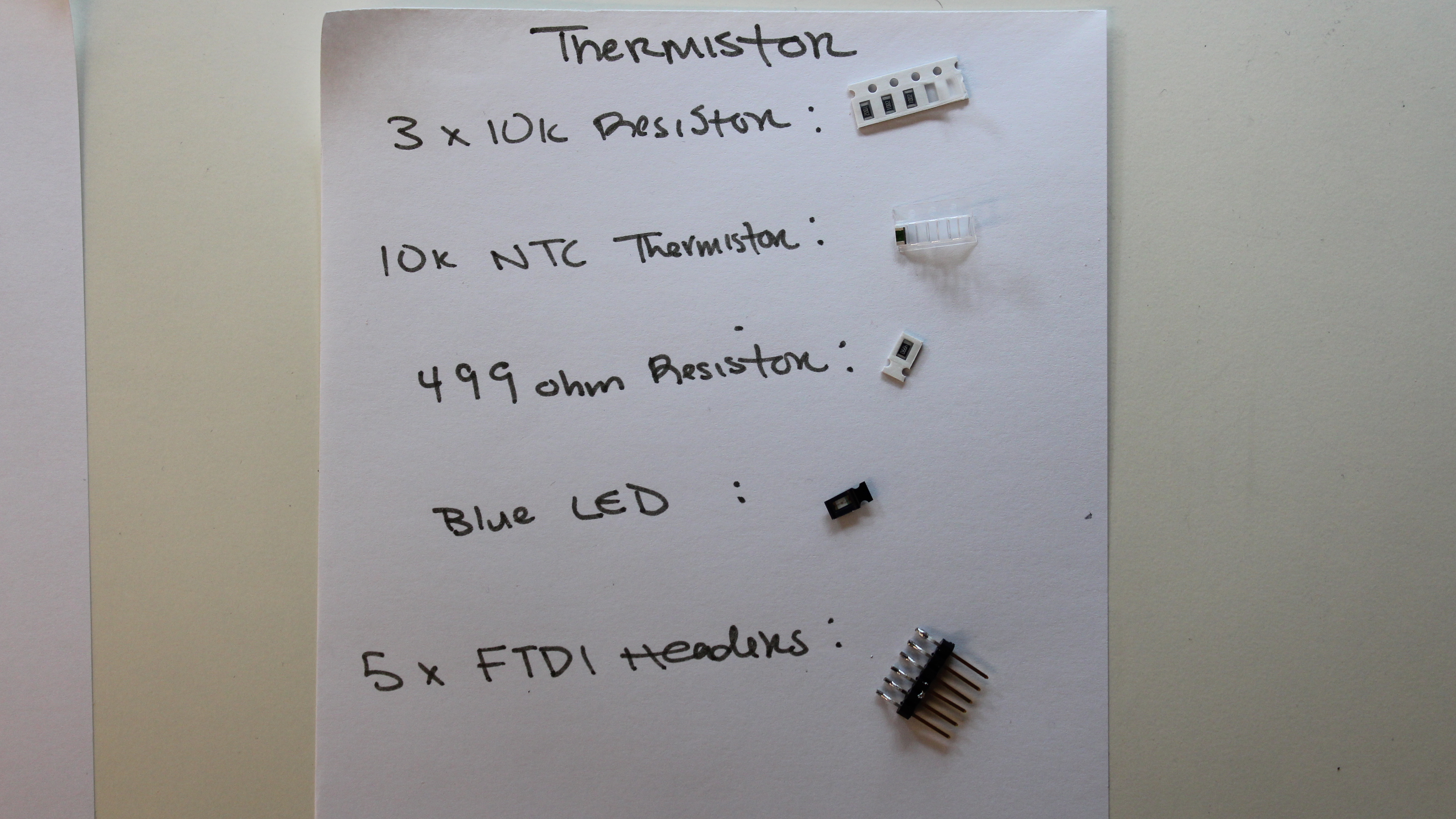
For this week’s assignment I decided to create only one of the peripheral boards from my final project. The board I am creating is the temperature sensor board. Similar to Week 8 I used Neil’s thermistor board as a reference for my design. The components of my board are:
- 3 x 10k ohm resistors
- 10k NTC Temperature Sensor
- 499 ohm resistor
- RGB LED

I also added connectors to connect to 5v, 3 pins and GND on the Barduino. Essentially my board is a light weight version of Neil’s. For the layout design I decided to use Adobe Illustrator because I already have the LED and resistor in vector form from previous weeks and the board design is really simple. The one thing I had to make sure I got right was the scale of my board design. For this I used a previous layout design from a past week as a template.
Barduino

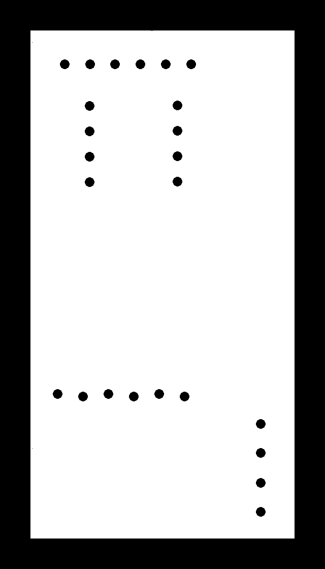
Thermistor


MILLING & STUFFING
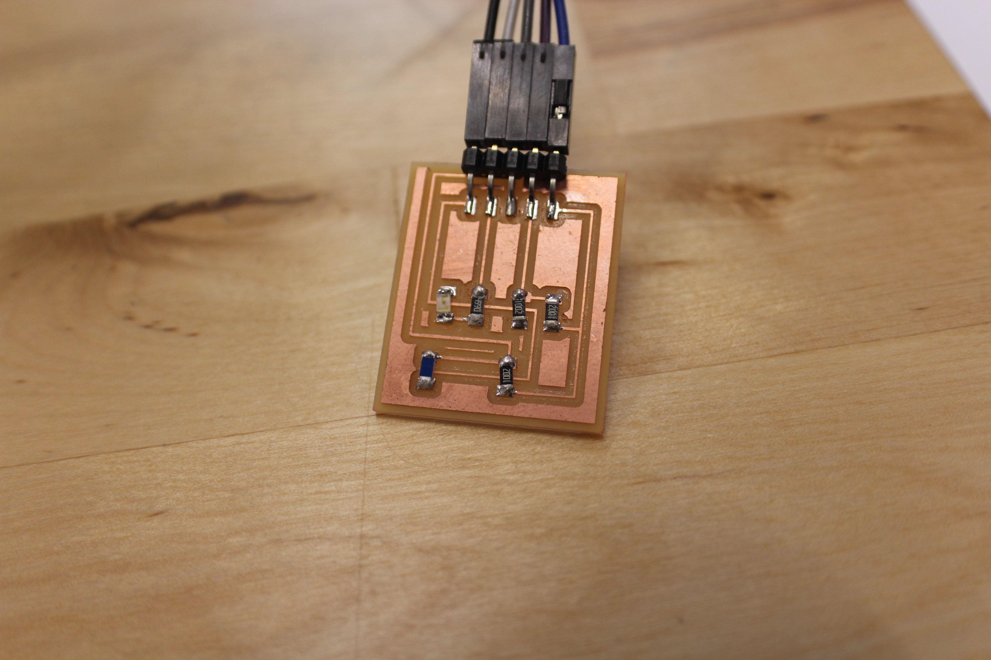
With traces and outline for both boards complete, I was ready to start milling my boards. I first milled the thermistor board because It was the simplest out of the two and I would be able to stuff the board as the Barduino board mills.

When milling my Barduino board I did run into some issues. For some reason the traces for the Atmega328 pins would not mill correctly. Some of the pins would be connected which is an obvious problem. After some brainstorming and help from Luciano, I was able to fix the problem. I had to edit the trace file and thin out the pins that were coming out connected during the milling process.
At the point in the Fab Academy I am proud to say my soldering skills have improved drastically. Soldering both boards went smooth. There was one moment that proved to be tricky which was soldering the ATMega328. It was my first time working with the chip. I followed the stuffing tips in the tutorial mentioned above but it took me a few tries to get it perfect.

PROGRAMMING
The next step is to program my Barduino. I will be using my Arduino as an ISP to program my board. The wiring and connection set up was the same as my set-up during my Week 6 assignment (http://archive.fabacademy.org/2018/labs/fablabdassault/students/oyedotun-ajweole/exercise06.html). Once the connections are secure, I connected both boards to my laptop and opened the Arduino IDE. Before proceeding I made sure to select the correct board setting in the Arduino IDE
Board: Arduino Pro or Pro Mini
Processor: ATMega328 (5V, 16Mhz)

I then tried to burn the bootloader onto my board but ran into an error. I was receiving an “unexpected signature” error every time I tried to run the bootloader. Reading the tutorial this seems to be a common error and has to do with the different version of the ATMega328, such as 328P or 328AU. Following the steps in the tutorial I had to change the set device signature for the atemega328P from 0x0f to 0x14. I tried again and was still receiving the same error.
Error Fixed! So it turns out there was a problem with my original ATMEGA328. Luciano thinks when I was initially trying to burn the bootloader to my board through my Arduino, there may have been a short or wrong wiring that possibly fried the board. Once I replaced the chip with a new one, burning the bootloader was a success.
READING TEMPERATURE
Before programming my Barduino to read temperature I had to assemble my boards. The pin header connected to LED will go to pin #5. The pin headed connected to the two 10K resistors will go to analog pin #0. The pin header connected to the NTC thermistor and 10k resistor set up will go to analog pin #1.
Picking up form where I left in Week 8, I uploaded my TEMP_SENSOR code to my Barduino and adjusted the pins numbers to match the new pin layout. The code works but I noticed something was off. The temperature reading I am getting is very low. At room temperature my sensor is reading around 25 Fahrenheit.
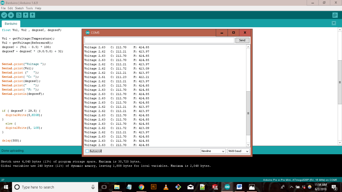
I am not sure what the cause of this problem might be. My first attempt to troubleshoot this was using a multi meter to check if my board had any short circuits. There were none to be found. Next was checking the calculations in my code. In order to get the temperature in Fahrenheit or Celsius from an NTC temperature sensor, you have to first convert the analog data into voltage and then the voltage into temperature. The code I was using did this using these equations:
Voltage = AnalogData * (5/1024);
degreeCelsisu = (Vol -0.5) * 100;
degreeFahrenheit = degreeCelsius * (9.0/5.0) + 32;
From what I read online these equations seem to be correct. So why am I still receiving bad temperature readings? Upon more research and googling I found the answer.
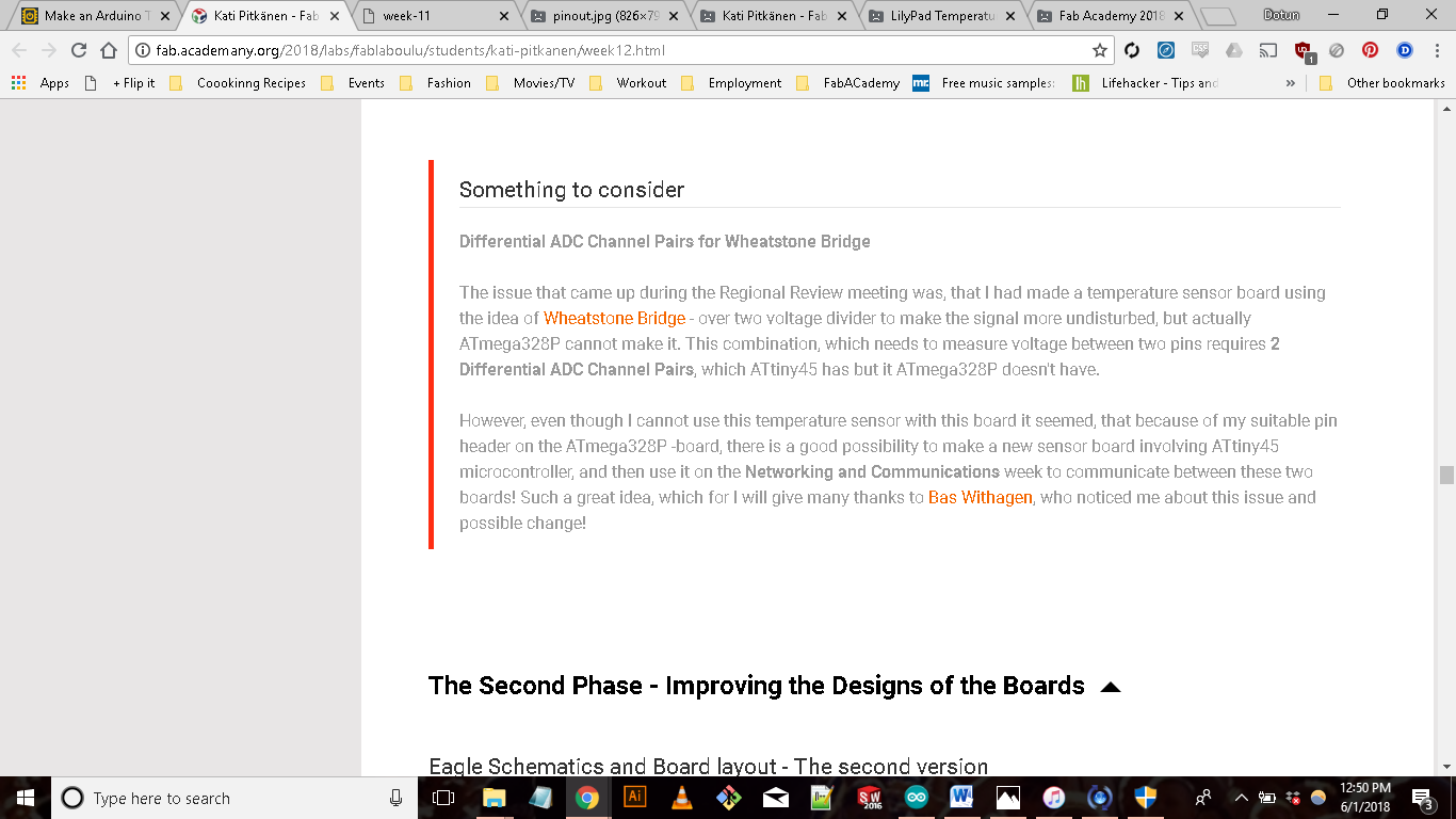
A Fab Academy 2018 Student, KATI PITKANEN
(http://fab.academany.org/2018/labs/fablaboulu/students/kati-pitkanen/week12.html)
Reading this was kind of a bummer but at least I know this moving forward. Luckily I didn’t have to scratch the temperature board I made I only had to change the wiring and code for the board to work properly. Following this tutorial (http://www.circuitbasics.com/arduino-thermistor-temperature-sensor-tutorial/) I rewired my board, this time connecting the NTC Thermistor to power and the resistor to ground. The biggest change I made was to the calculations. Instead of calculating temperature from voltage, I calculated temperature from the resistance. Here is my new code
int Temperature= 1; //determine the type of data and signal the pin
float sensorValue;

// the setup function runs once when you press reset or power the board
void setup()
{
  // initialize digital pin 13 as an output.

  Serial.begin(9600);
  Serial.println ("Hello I am Working");

 }

// the loop function runs over and over again forever
void loop() {

sensorValue = analogRead(Temperature);              // Read and store the analog input value coming from the temp sensor pin

double TempC, TempF, T;                                 // Define the variables to show the temperature data
double R = 10000 / (1023.0 / sensorValue - 1);  // Steinhart - Hart    /// Resistance = 10 k ohm     /// (2^10 = 1024)
double L = 10000 / R;                           // L = R0/R // 10000/R = ReferenceResistance/ NominalResistance = ResistanceInNominalTemperature25oC)

  //T = 1.0/((1.0/(25.0 + 273.15)) + (log(R0/R))/3750))
  //T = 1.0/((1.0/(25.0 + 273.15)) + (log(L))/3750) * log(L))
  T = (0.0033540164 + 0.00026666666 * log(L));    // Steinhart-Hart 1/T=1/T0 + 1/B*ln(R0/R)
  T = 1/T;

  TempC = T - 273.15;                              // To get Celcius degrees Temperature = T - 273.15 (Kelvin degrees)
  TempF = TempC * (9.0/5.0) + 32;                 //Convert Celcius to Fahrenheit

  Serial.print("Celsius ");                   // To print information to the Serial Monitor
  Serial.print(TempC);
  Serial.print(" C ");
  Serial.print("  |   ");
  Serial.print("Fahrenheit ");
  Serial.print(TempF);
  Serial.println(" F ");


delay(500);


}
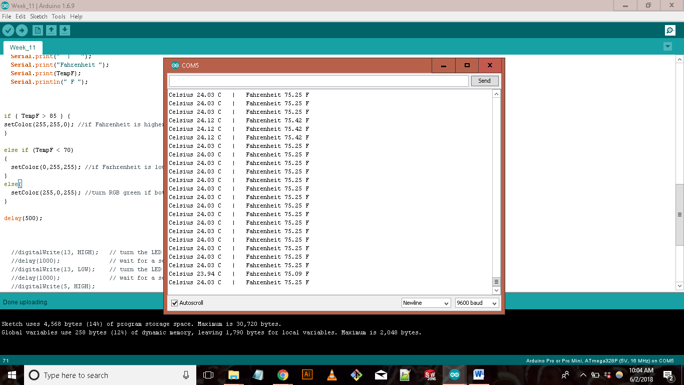
I uploaded the code into my Barduino and the temperature readings looked a lot more reasonable. To verify this, I compared the temperature reading from the lab central air system against my temperature reading. There was a ~5 degree difference in the temperature I was receiving from my board but this is not too bad. I think I can fix this with more calibrating.
Next I will connect my RGB board and make it react to the changes in temperature
TO BE CONTINUED......WEEK 11
FILES:
Barduino:
Barduino Schematic
Barduino Layout
Barduino Traces
Barduino Shape
Thermistor:
Thermistor Illustrator File
Thermistor Traces
Thermistor Outline