The chip that I’m using is Attiny44. I had no idea how I was going to start. First I looked at examples that Neil had on the website and things that he show during the lesson. So I chose what sensor I wanted to used, since I need it a sensor that detects things. I decided that I wanted to used the sonar sensor. I’m going to used this sensor for my final project.
Although he used a the chip Attiny45. I mill one of his board and I couldn’t it make it work . I looked the datasheet for the Attiny45 to see what pins Neil used for the sensor. So I decided that I was gonna make another board, but this time I will used the Attiny44. So what I did I open the schematic of my Hello-World, because I noticed that it uses the chip Attiny44. By looking at the datasheet I learn the position of the chip and pin configuration. By looking at the pins configuration I noticed that are digital and Analog pins. A chip can input and output analog signals as well as digital signals. Analog signal is one that can take on any number of values, unlike a digital signal which has only two values: HIGH and LOW. The function used to output a PWM signal is analogWrite(pin, value). pin is the pin number used for the PWM output.
Looking at the datasheet was so helpful because this helped my realize which pins I should used. So I started to add things to my schematic. One more thing I learn by searching which pins transfer or display the data in the serial monitor. I learn that the pins that transfer that information are rx and tx.
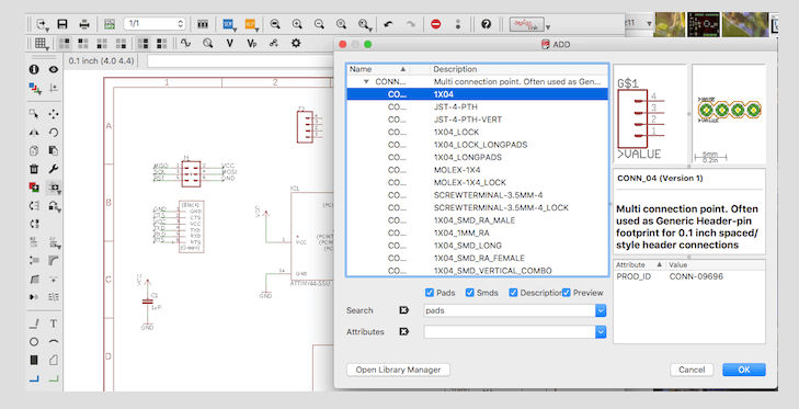
So I started to add components into my schematic. I added all my components to my schematic. The way you add symbols to the schematic is you click on edit and then add. If there is something that you need and is not in the library or the fab library you can search for it on the internet. In github they have a lot of libraries of symbols that you can add to the eagle library.
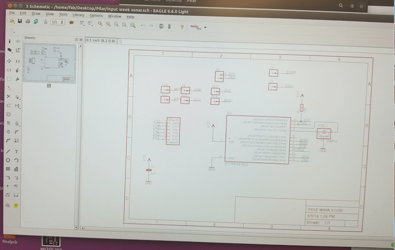
This is how my layout of my schematic for my Sonar-Sensor.
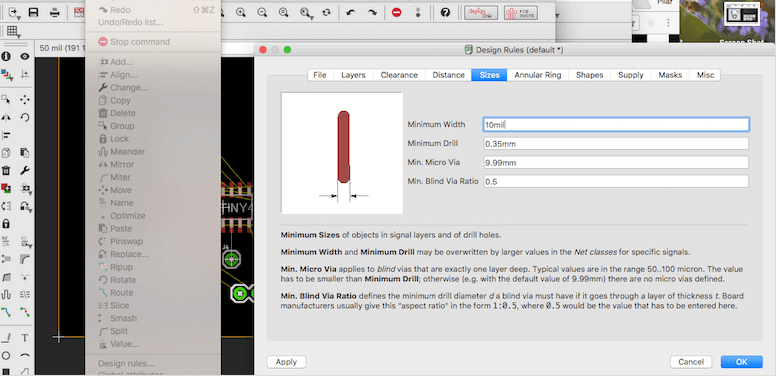
Now that I have my schematic ready I can design the actual board. All my boards I have been connecting the traces 1 by 1 because everytime I used to do automatic traces they will come out really thin. But this time I spend time searching where should I change the thickness of my traces. So I learn that if I go to design rules, then I clicked on sizes then it will change the thickness of the traces in the automatic option. This time I just ran the the automatic option.
Board designed
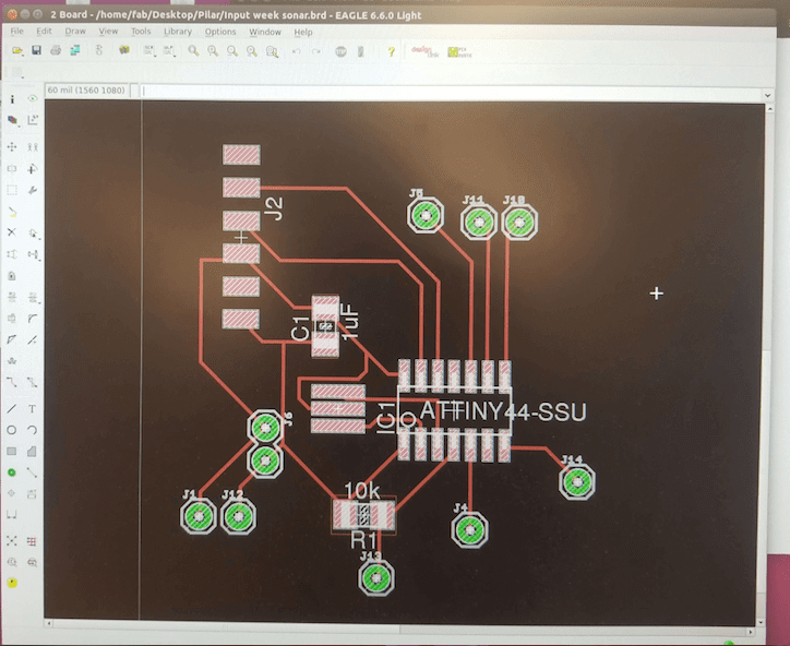
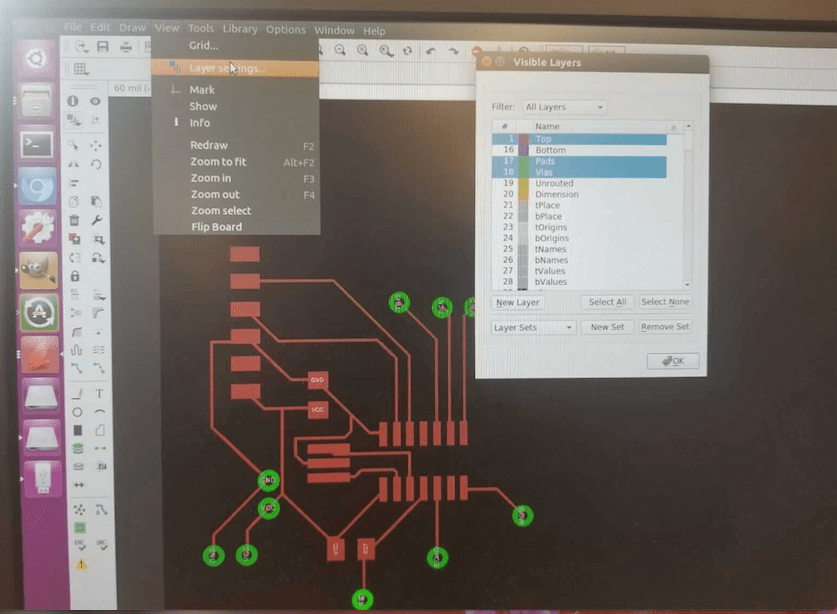
In order to finish my board and to get it ready for the png traces, I had to go to layers and only select top, pads and vias.
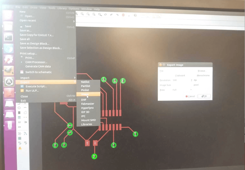
Finished designed my board. First I clicked on the export option, second click on image and thirdly a box will come up with options. The box is called Export image choose where you want to save your file, then monochrome and 500 dpi.
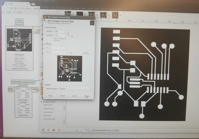
I opened my board in GIMP. So now I just cropped close to the traces but not so close. Then I click on the option image then set image to canvas size. In the window that it appears click on the chain and Neil recommended to add 20 px. We add 20 so we can make the outside trace. Then I clicked on canter and finally do resize. Lastly clicked on flatten image. Then it will fill the outer edge with that's the extra 20px that we add.Then to make the picture for the outer edge, I choose on the paint option to fill in whatever is white is it can be fill on black because the color black the machine does not mill it only the white. Then to save the picture to png I clicked on the option file export and then you select png.
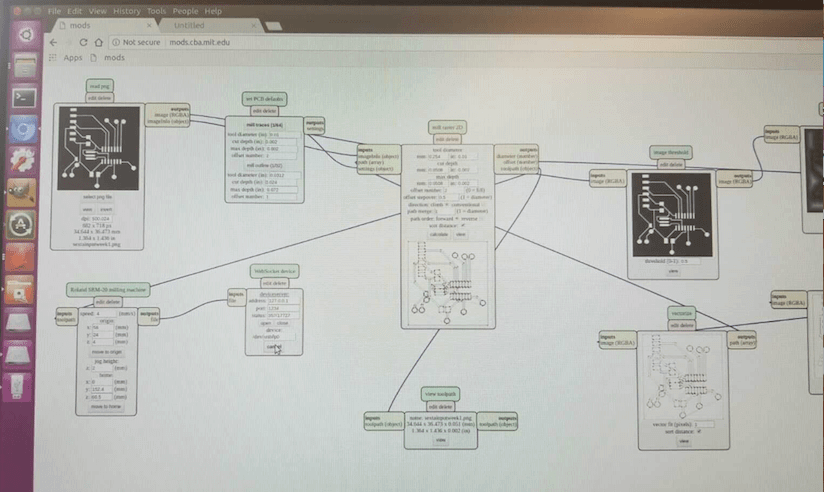
To cut my file on Mods so I click on open programs → open server → rolland mill → srm-20. Then a window like this will appear follow the boxes. Load png file, mill traces then prepare the machine select your X your Y and your Z. Your X and Y depends on where you place your material on the sacrificial layer. Then your Z you lower the head and then free the drill until it touches your material now you are ready to cut. Click on calculate and finally send and this will send it to the machine. Now my board is cutting.
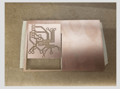
My board is cut . I wash my board so I could start soldering. Then I soldered all the components.
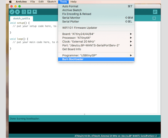
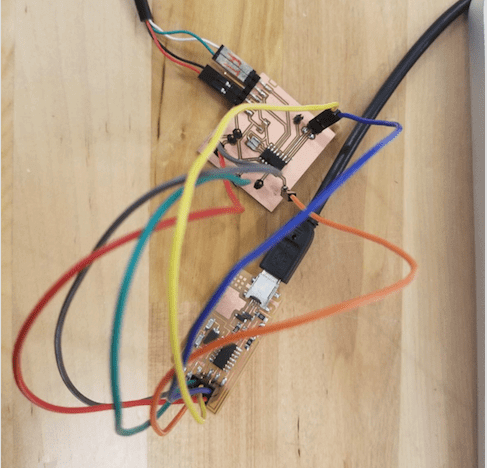
To burn my bootloader to my board. I connected my board to the arduino. In the arduino program I chose Attiny44, clock 20 MHZ, then my port. Lastly I clicked on Burnloader and in the window on the left side says done burning bootloader.
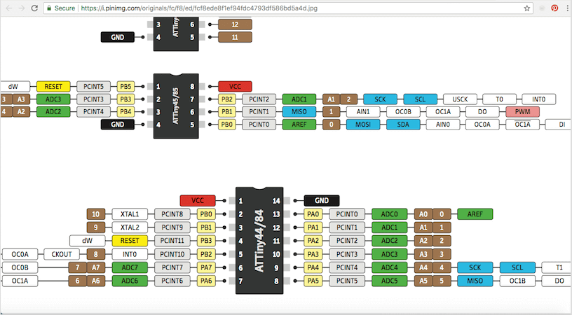
Arduino pinout. I used this picture to go back and looked at the arduino pinout it was very important because most of the examples that I used to make my code I used arduino language.
In arduino my serial was working just find, but when I put it into my board it did not work. I couldn’t get my serial monitor to work. It kept appearing something like port busy.
The data that is displaying in my serial monitor is showing my input. In my week # 11 output I got my serial to work. Now I went back to this week so first I declare my serial. I set rx and tx this to guys are very important because they transmit and receive information, this way my serial monitor was able to work. Also I had to download the FTDI serial driver because that is one of the reason why my FTDI was not working. So now my FTDI cable was listed in the ports, I upload my code to my board in the port I changed to the FTDI port and my serial started to read numbers.
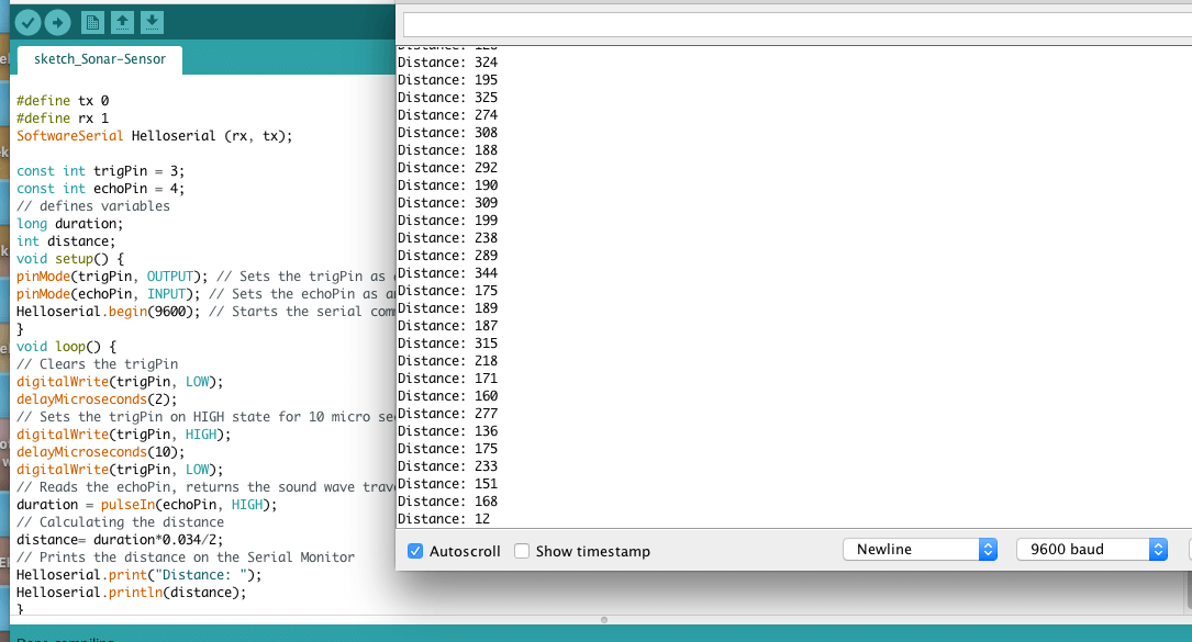
The last problem that came across was when my serial monitor page open was what my baud # was’t matching with my code. So I looked into the problem and this is what I learn and understood according to what I read. Baud is the measurement of the speed of communication over the data channel. In another words is the unit for symbol rate or modulation rate in symbols per second or pulses per second.
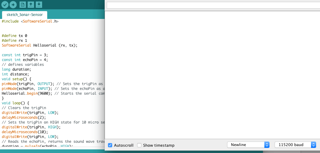
After going through all this problems, I’m so happy I finally make my board is displaying an input in the terminal.