For this week I choose that my output was going to be sound. I looked up online for examples of what people have done with sonar sensors and and sound. After watching a lots of tutorials I found a code that it was closer to what I wanted to make. During the lesson Neil recommended the Satsha Kit. The Shatshakit is very similar to what arduino does it has the same chip ATMEGA328P.
I upload the code to the arduino. It did not work I was not hearing anything. In the code I says everytime you see something sound is gonna play. Then I add two sound libraries. Libraries are a collection of non-volatile resources used by computer programs, often for software development. These may include configuration data, documentation, help data, message templates, pre-written code and subroutines, classes, values or type specifications. This is when I understood that I need it a librarie so my speaker can play the melodies that are written in the librarie. It's not like a piezo it only has one specific sound.
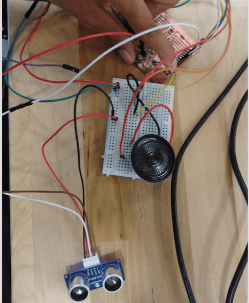
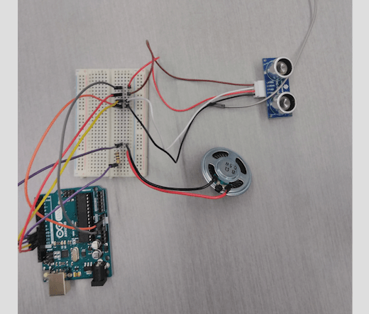
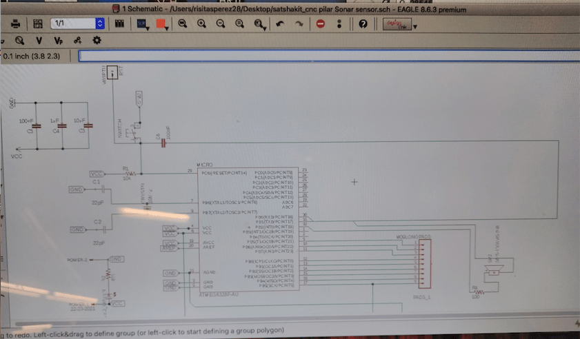
The things I need it to add in to the board are a speaker and a 10k resistor. Also I realize since I want to used this sensor for my final project I need it to add something that will turn on the sensor and when is off. So I ended up adding a push button. So I started to add components into my schematic. I added all my components to my schematic. The way you add symbols to the schematic is you click on edit and then add. Everything that I need was in the Fab library in eagle.
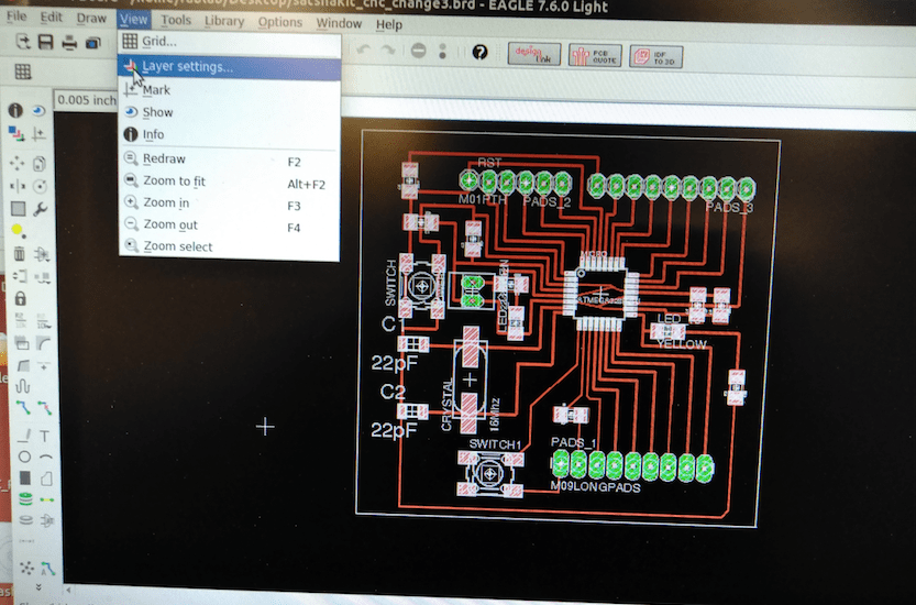
Now I know how to change the thickness of the traces. You go to design rules and the the window will pop up. Then you go to sizes and change the number where is says minimum width. That's what I changed and for me it worked. So I ran the the automatic option. Sometimes you still have to disconnected and connect some traces but is a little bit much faster.
In order to finished designed my board and to get it ready for the png traces. I had to go to layers and only select top, pads and vias.
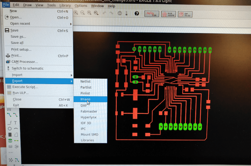
Finished designed my board. First I clicked on the export option, second click on image and thirdly a box will come up with options. The box is called Export image choose where you want to save your file, then monochrome and 500 dpi.
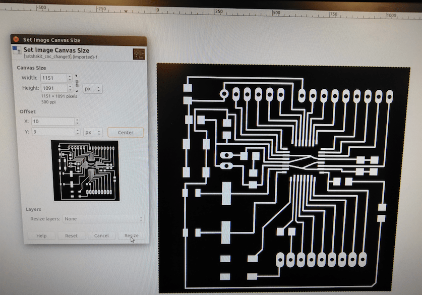
I opened my board in GIMP. So now I just cropped close to the traces but not so close. Then I click on the option image then set image to canvas size. In the window that it appears click on the chain and Neil recommended to add 20 px. We add 20 so we can make the outside trace. Then I clicked on canter and finally do resize. Lastly clicked on flatten image. Then it will fill the outer edge with that's the extra 20px that we add.Then to make the picture for the outer edge, I choose on the paint option to fill in whatever is white is it can be fill on black because the color black the machine does not mill it only the white. Then to save the picture to png I clicked on the option file export and then you select png.
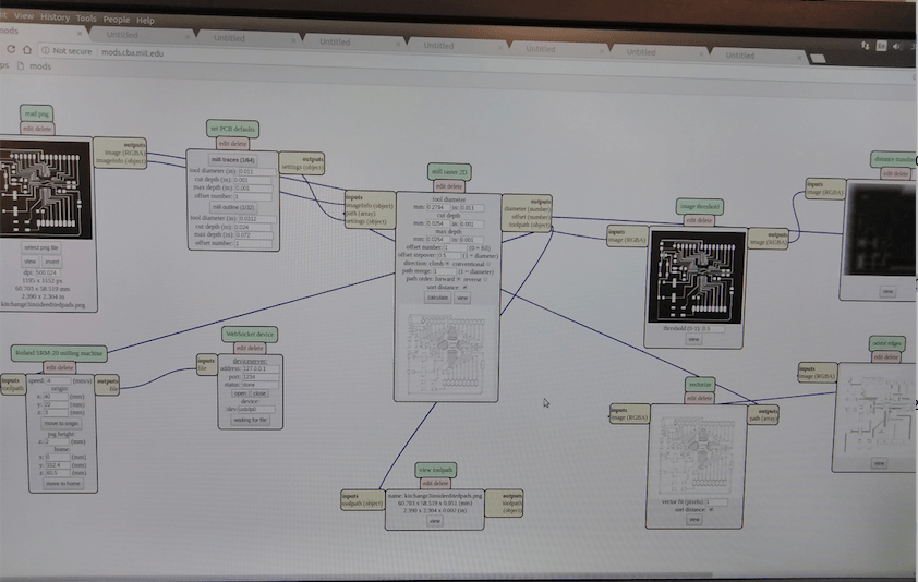
To cut my file on Mods so I click on open programs → open server → rolland mill → srm-20. Then a window like this will appear follow the boxes. Load png file, mill traces then prepare the machine select your X your Y and your Z. Your X and Y depends on where you place your material on the sacrificial layer. Then your Z you lower the head and then free the drill until it touches your material now you are ready to cut. Click on calculate and finally send and this will send it to the machine. Now my board is cutting. Had to cut my Satsha Kit like 6 times because the traces will ripoff. The way I solve the problem was I kept trying with different settings until it did it. I change the cut depth, the diameter of the tool and how many time it was gonna pass on the traces.
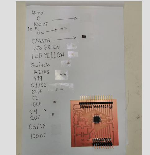
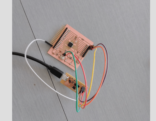
My board is cut . I wash my board so I could start soldering. Then I soldered all the components.
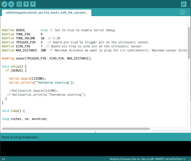
To burn my bootloader to my board. I connected my board to the arduino. In the arduino program I chose the option as regular arduino because is using the same chip, then my port. Lastly I clicked on Burnloader and in the window on the left side says done burning bootloader.
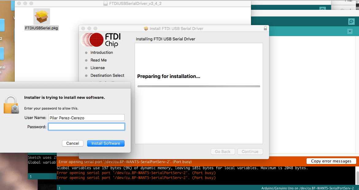
One problem that I ran into was the same as the previews week. My serial monitor was showing up the same problem. It cape appearing something like port busy. So I realize that the FTDI libraries were not in my computer anymore. So that Solve one problem.
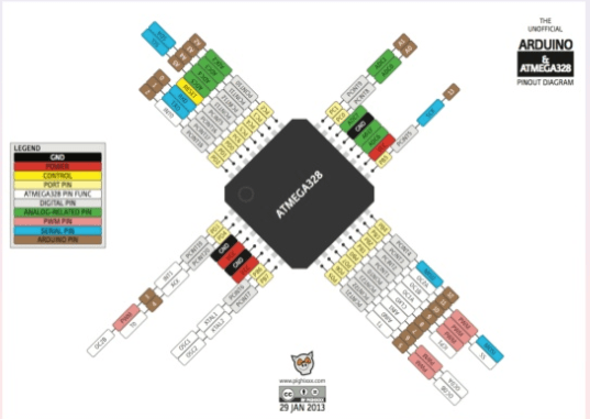
This picture and the data sheet helped me to match my pins, transfering from arduino to the satshakit. When I put everything together it did not work. It did not work because instead of pin #9 and pin #10 I used another pins. But then I showed to one of my instructors and helped me looked through the libraries information and it said that the libraries are set to work with does 2 pins.I still could it get it to work but I searched the problem and it says that is order for the serial monitor to work you have to include the #include SoftwareSerial.h and then define my tx and rx. #define tx 0 #define rx 1 SoftwareSerial Helloserial (rx, tx);
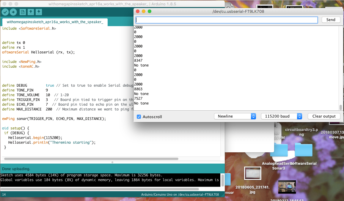
In this picture we see that is displaying numbers int the terminal so is giving an input to my output
Libraries for sound are added to my code sensor is connected a push button is also added to turn on and off the sensor so if the user is pressing the button the sensor will make a small sound, but if the sensor sense something then my speaker is gonna make a harder sound and different.In my code the pins that im using is #9 and #10 for my speaker