Molding and Casting
My son explained to me that he saw a You-Tuber hack a Rubik's Cube to make the middle-edge pieces "dissappear" so he was left with only corner and center pieces. The You-Tuber accomplished this by hacking away at the plastic pieces to remove the bulk of the material. We tried to do the same by setting up a jig on my drillpress and slowly machining away the plastic. Unfortunately, we epically destroyed several pieces, because the model we were working with had thin plastic walls that would get caught up on the drill bit - The model the You-tuber hacked had solid pieces.
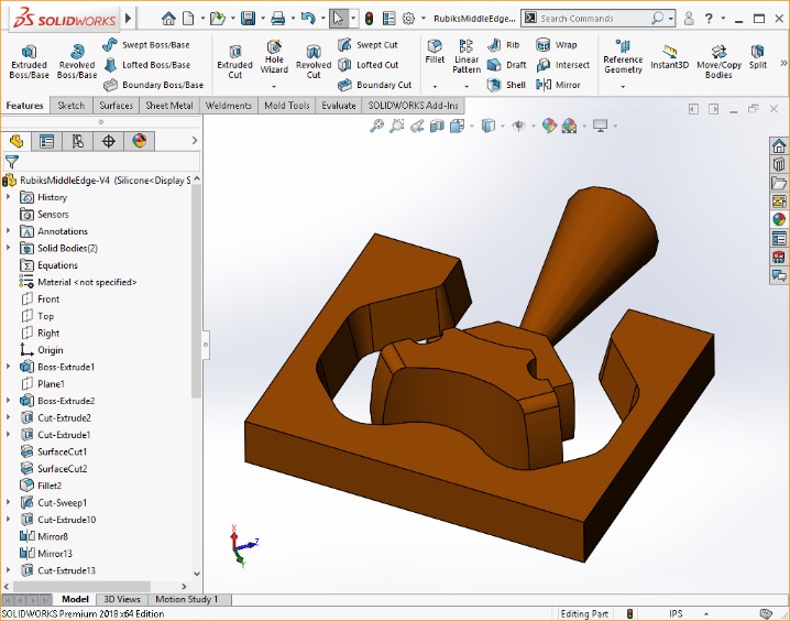
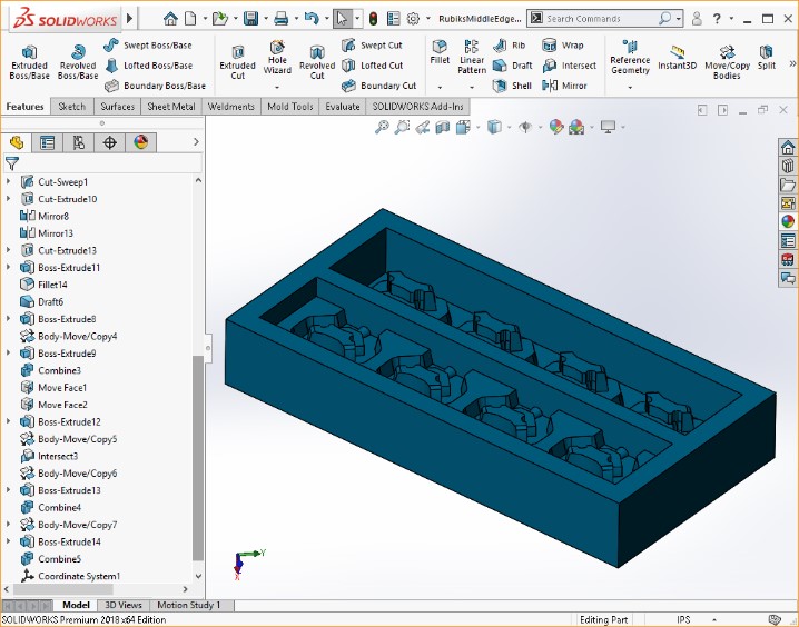
Knowing that Molding and Casting was in this class, though, I put the mission on the back burner and waited until this week! Excited to get started, I first came up with a design that could replace this standard piece (shown at two viewing angles):
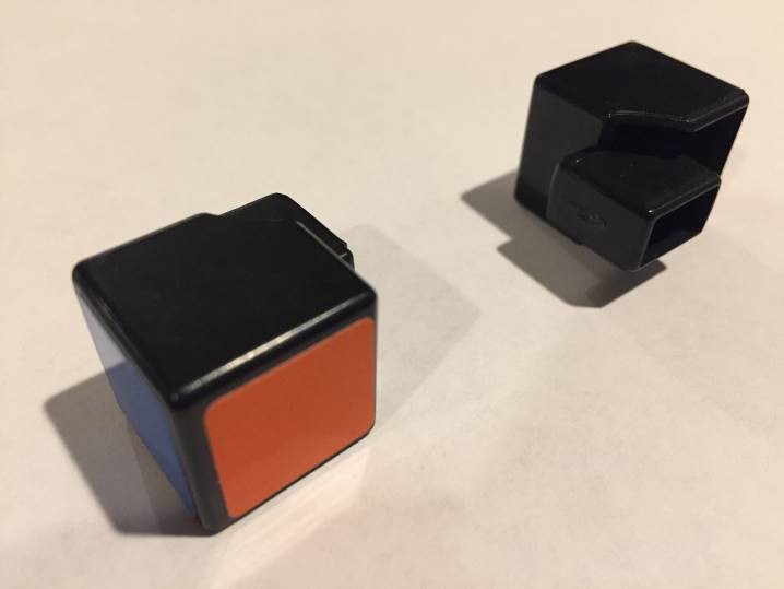
It still had to have all of the critical bearing faces and match the dimensions really closely, but I could take liberties with the user-visible geometry. I wanted to make this piece "disappear", but of course it was still going to be seen, so I gave it a somewhat intersting shape. Here's my design (shown at the same two viewing angles).
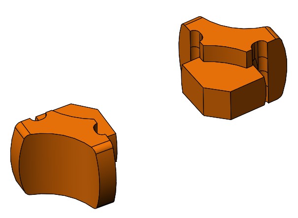
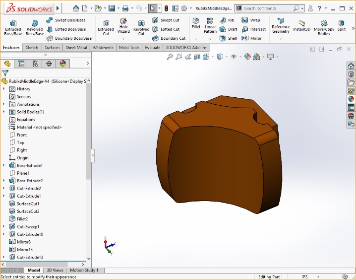
I used calipers to take critical dimensions of the original part and designed the geometry in SolidWorks.
Happy with the design, I turned my attention to designing the gate into which I'd pour the plastic, as well as geometry that would produce a solid "registration" when the two halves of the mold were put together.
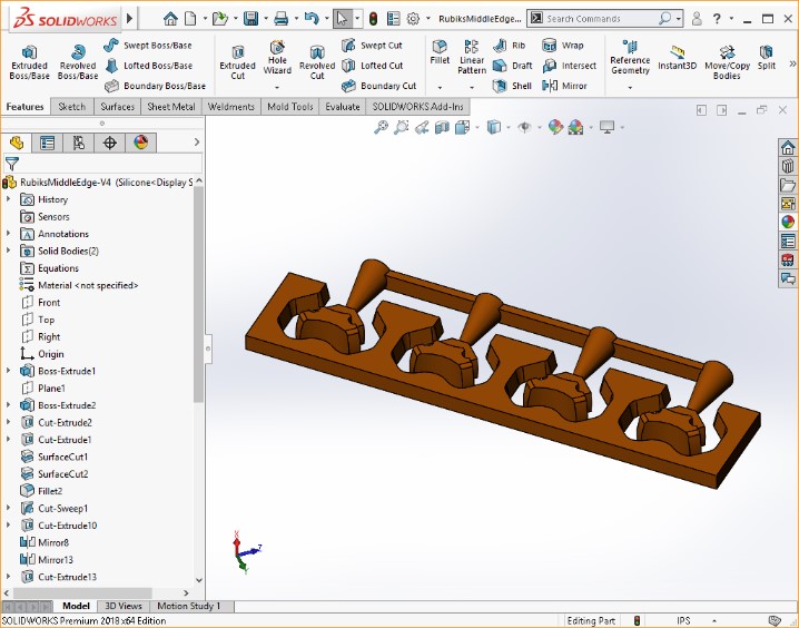
Since I needed to produce 12 pieces, I decided to make a 4-cavity mold. I used a Move/Copy Body feature as well as a Combine feature to create this 4-shot piece:
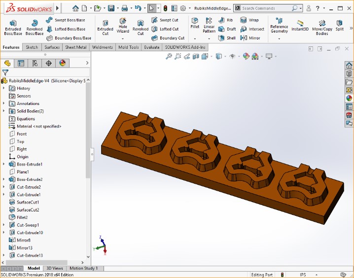
...and then build the silicone mold half by creating a solid rectangular prism and subtracting all of the above geometry from it.
To create the other half of the silicone mold, I extruded another rectangular prism and once again subtracted the 4-shot plastic part as well as the other half of the modl from it.
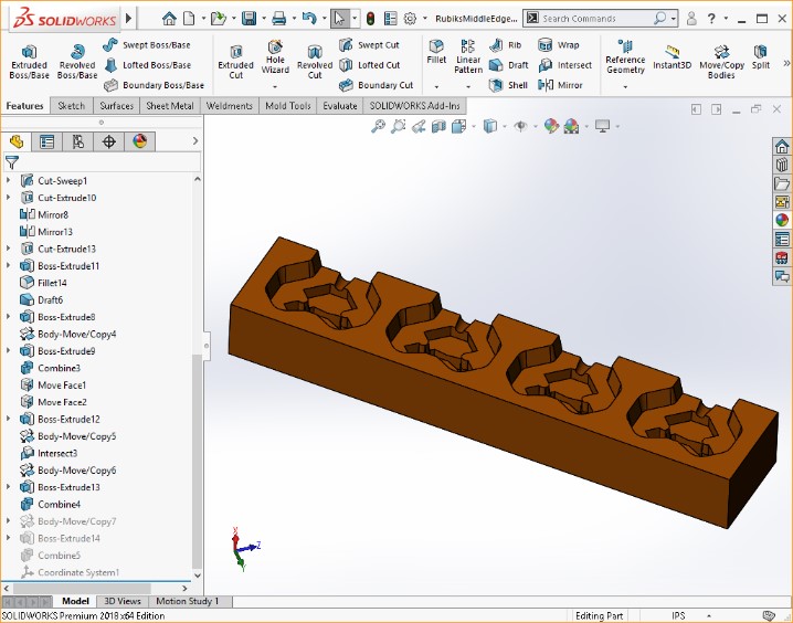
Creating the wax mold was a simple matter of positioning the two halves of the silicone mold in one more rectangular extrusion and subtracting them from it.
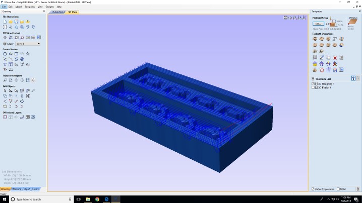
At this point I turned my attention to creating toolpaths in V-Carve. To start, I exported an STL file from SolidWorks and imported it into V-Carve. I created a rough toolpath using a 1/4", 2-flute, spiral up-cut bit:
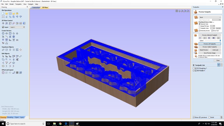
...followed by a finish toolpath using a 1/8", 4-flute, flat end mill (you'll see later why this was a bad idea):
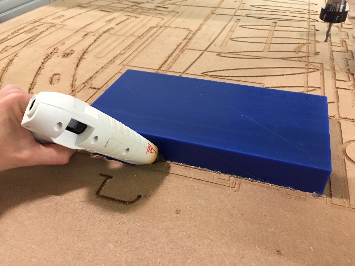
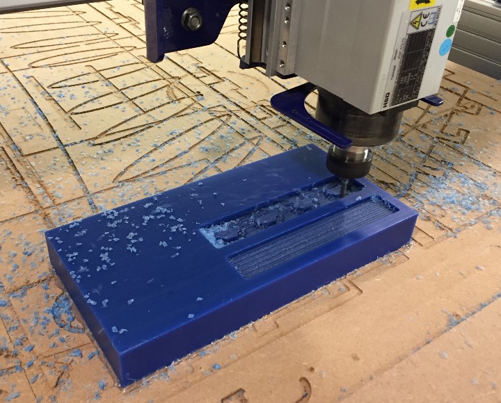
I setup the wax block on the Shopbot, using hot glue to hold it in place.
Then I zeroed the bit and ran the rough tool path. As you can see, I left the dust collector shroud off and manually vaccumed the chips with a portable shop vac. My aim was to not contaminate the dust collector with wax shavings, but this manual approach meant I had to stand over the machine and baby it so the wax chips didn't build up in the mold. In the future, I'll take the time to change out the dust collector bag (or just allow the chips to mix with the sawdust).
When the rough pass finished, I changed the tool to the 1/8" bit, re-zeroed the "Z", and started the job. As you can see from this image, the 4 flutes produced too much heat in the mold and things started to melt. I thought I calculated my chip load properly, but perhaps I made a mathematical error. What I learned aftewards is that I should favor a single flute bit over a many-flute bit when working with wax. It turns out that wax chips are not as effective at dissipating heat as wood or metal chips do.
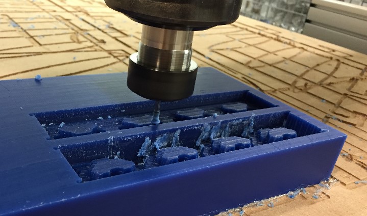
Ah-well... Lesson learned.
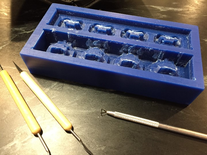
To tidy up the mold, I spent a few minutes shaving a some areas down usnig some clay carving tools I borrowed from my youngest son :)
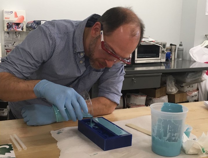
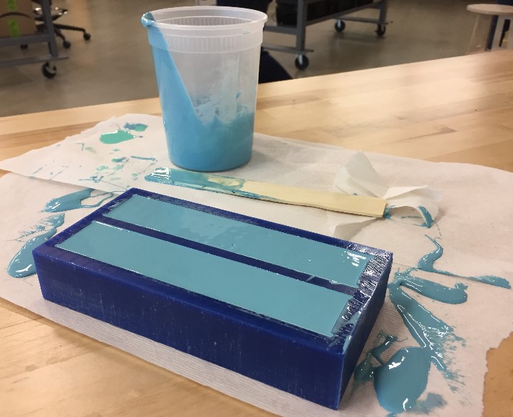
With the wax mold all prepared, I moved on to mix and pour the silicone. I used Oomoo as it can easily be measured in equal parts by volume and has a 15 minute pot time. When pouring the mixture, I poired as thin a bead as I could and made sure to pour from the lowest point of the mold to avoid trapping air bubbles.
Although I suppose this next step is unnecessary for most molds, I chose to squeegee off the top of mine so that the resulting silicone molds were nice and flat. I did this because I wanted to also produce a wooden box to house the mold while I poured the plastic.
I used SolidWorks to design the pieces and created a drawing that I exported as a DXF.
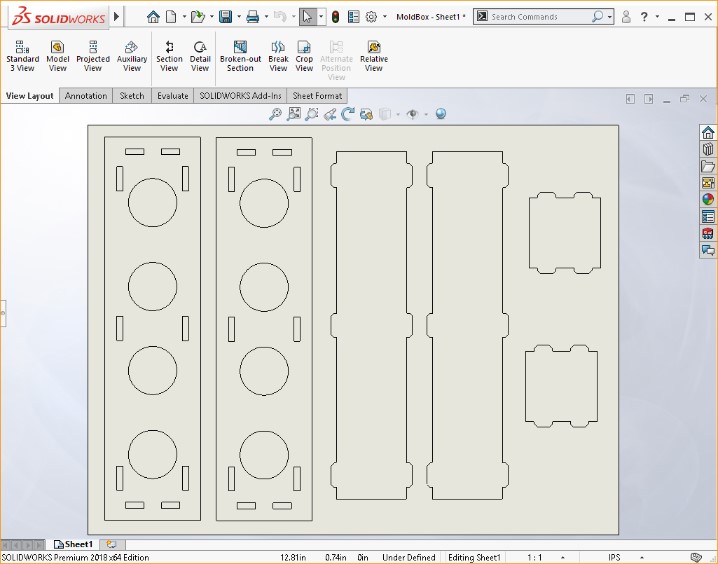
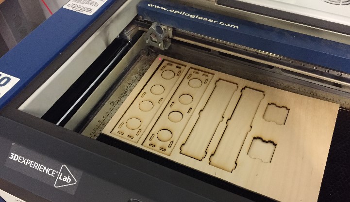
I imported the DXF into Illustrator and cut the pieces out of 3mm plywood on the Epilog laser cutter.
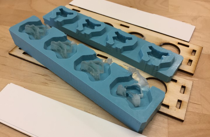
With all the parts now ready, I de-molded the silicone parts...
...then sprayed them with mold release.
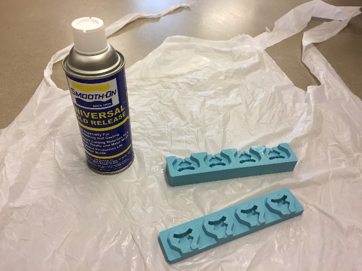
A few minutes later, I assembled the two silicone halves together, and then trapped them in the wooden box.
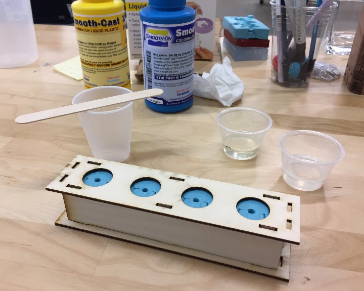
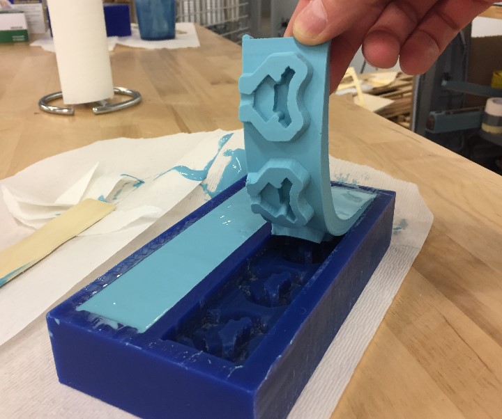
I then mixed liquid plastic and poured it into each of the four cavities. As you can see here, one of my pours was a short-shot. I clearly got a giant air bubble trapped in the mold when I poured that cavity. To correct this on subsequent pours, I manually enlarged the gate by cutting away silicone with a utility knife. This provided ample space for the plastic to flow and the air to escape.
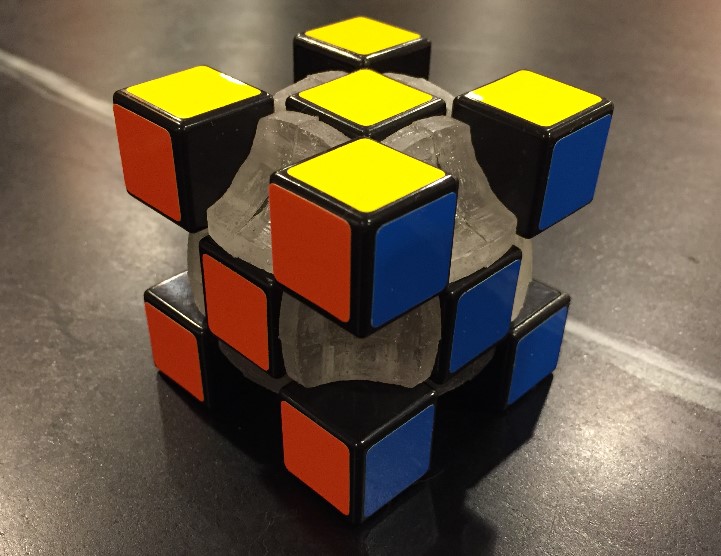
To finish the project, I molded a few more sets, cut away the gates on each piece, and then assembled 12 of them into an edgeless Rubik's Cube!
Both my son and I are quite pleased with the results!