Electronics Design
redraw the echo hello-world board
Using Eagle Software
It was interesting to use Eagle Software for the first time.Step one was reading the tutorial carefully to learn the concept behind this assignment. Next I did a little practice following the tutorial "echo hello-world board" and I faced one thing that gets me a little confused about how search in the library to find the right components. Later on, I figure out that I have to open the library before to starting dropdown components. By the way, I had download fab.lb which provides by fab network also maintains a library, so that I can easily find the components. All you need to open the fab.lb is copying files to the director library of Eagle and open the software then go to library on the left list right click and choose use all.

After copy the library to the director
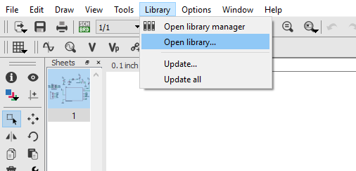
browsing the library to select fab.lb

browsing the library to select fab.lb

Write down the device name to be easy to dropdown the components later
Eagle software
Draw the schematic and the board
First of all, create a project then create new schematic. On the schematic, you will add the following components:
- ATTiny44 and to find it we write down (*ATTINY44*)
- 1 2x3 pin-Header
- 2 10Ω Resistance and to find it we wirte down (*RES-US*) the look in to R1206
- 1 499Ω Resistance
- 1 uF Capacitor and to find it we wirte down (*CAP-UNP*) the look in to C1206
- 1 6 pin-Header-Male and to find it we wirte down (*FTDI BASIC*) then look in to 1x06SMD
- 1 Button
- 1 LED

search and the components to the schematic

The schematic after add all the components
now go to file > switch to the board

In this stage, we move, rotate, and wired the components

On the layer settings > select top

Save the board as an image for a reslotion 500 dpi and check in Monochrome even the image become white and black

The board

The ISP Trace Layout
Download: Trace Layout

The ISP Cut Layout
Download: Cut Layout
Download: SVG file
Eagle software
Draw the schematic and the board
Once you finsh installing the Fab Module MDX-20 will be able to open the web page of Fab Modules

Inserting the Trace Layout
- Select the image(.png) for the ISP Trace layout as png
- Roland mill (.rml)
- PCB traces (1/64)

- In the output machine choose the MDX-20
- Write down your xyz 0 axis

Calculating to milling the board

The Instruction to cut the ISB

the cut depth = 0.85 mm
The stock thickness = 2.3 mm
Calculate and send to machine

After trace the layout for the ISP
_________________________________________________
Soldering the ISP
Using SMD Components
The Electronics Components that used for the module:
- 1x Attiny 44
- 1x 499 ohms
- 2x 10Ω Resistance
- 1x uF Capacitor
- 1x 2x3 in pin-header
- 1 6 pin-Header-Male
- 1x Button
- 1x LED

It takes one hour to finalize the soldering