1. Project Management
Ideation
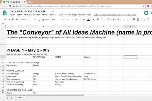
This week's assigment is to design and build a machine. We start by having some discussion about a potential project. After some group reflections, the team members choosed to build a machine to draw. We decided to use Excel to plan the project management. This collaborative project was definitely going to be a work in progress. It should be noted that because of health issues, Geoffroi wasn't there the first week.
For the first proposal, we thought to use a funnel dropping glue on paper with a mechanism dreopping sand on top of the glue, making artistic drawing. But, we opted to use a sharpie felt pen to facilitate the realization of the project.
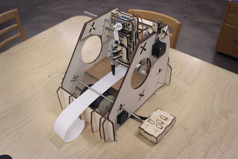
Thus, the idea of the project is to create a machine capable of drawing on a sheet of paper autonomously. There will be a wood structure that will incorporate the following: a roller system to feed the paper (rotation), a lateral displacement system (X Axis) and a system to move up and down (Z Axis) for the marker.
Software we used:
For this project, we mainly used the following softwares:
2. Prototype
Exploration
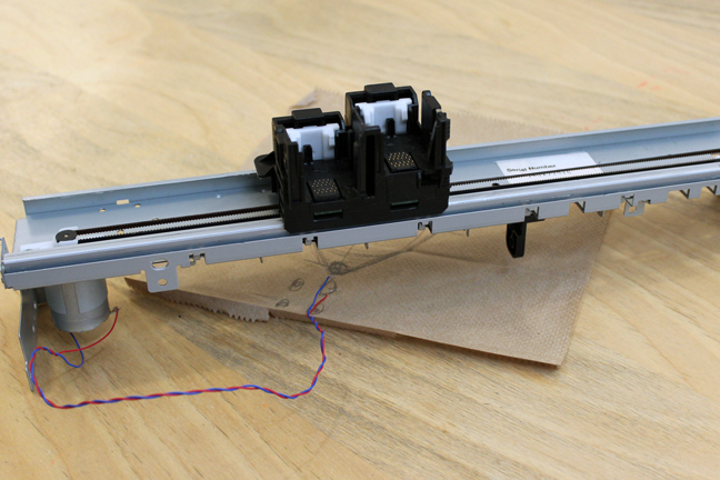
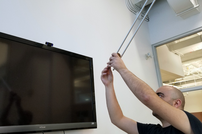
From the beginning of our experiment, we discovered a classic printer mechanism that was going to be thrown away. We decided to test it and see the possibilities of using it for our project. We were able to understand the movements. Finally, we did not decide to keep this mechanism as it was much simpler to design from scratch.
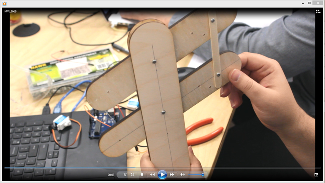
We experimented with different mechanisms for the Z module that holds the pencil.
Prototyping Structure : first version.
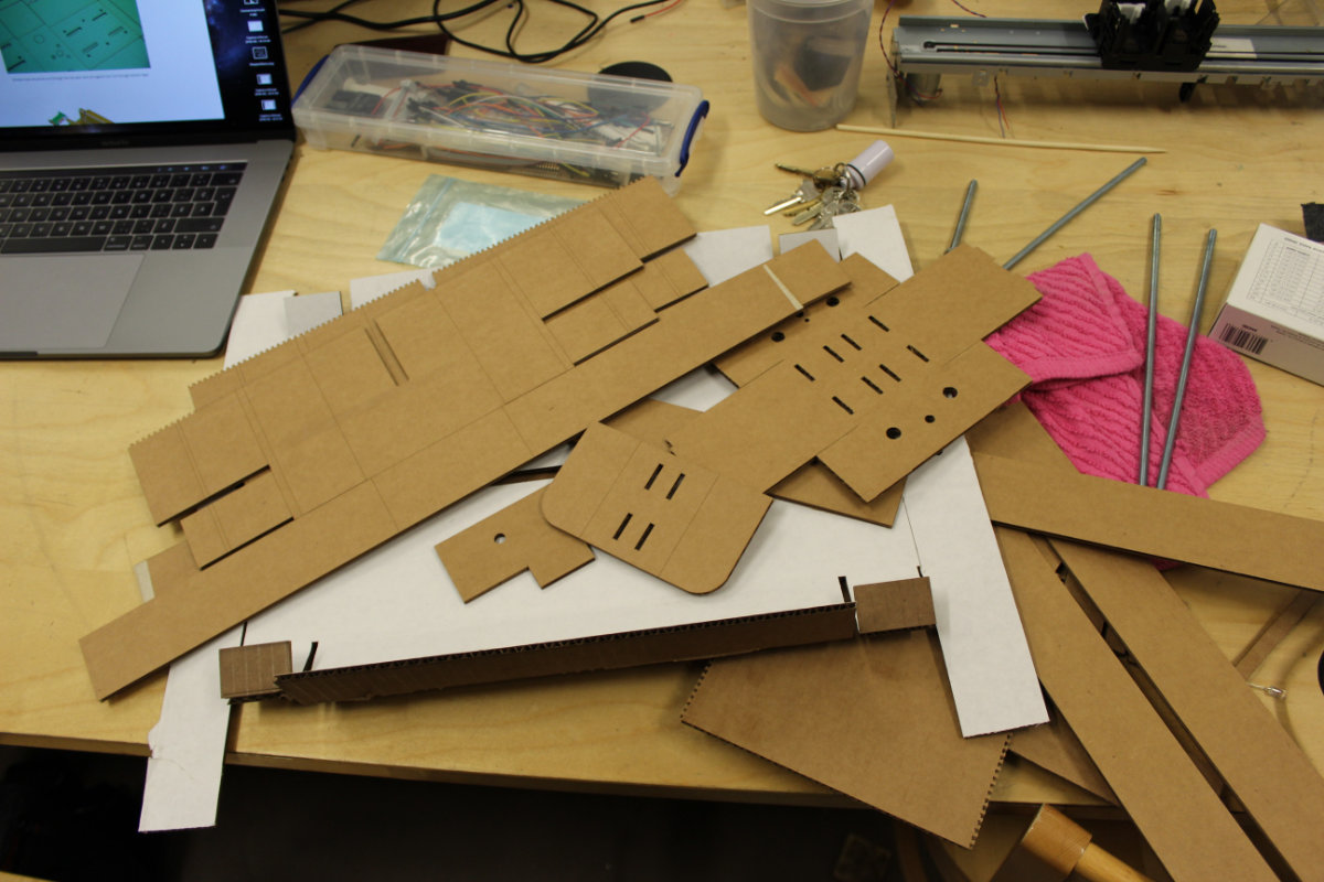
We built the first version of a structure with cardboard.
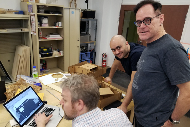
The first step was to create cardboard prototypes to verify strength, layout, and other features. This proved really helpful in getting our ideas out quickly and to cross-check with each other to see what would work best. We wanted to visualize where the motors, rods, and other mechanisms would need to be placed. We knew that we had very little time with our busy schedules so our objective was to use these quick iterations to be more efficient when moving to our final materials.
One of the first challenges we faced was to decide how we would build the system that would feed the paper. Ideally this would be as simple as possible. We looked at the different gears and adaptors that we could find in échoFab's collection of discarded electronics. It became clear that this process would require far more 3d printing and time calibrating belts etc. so we eventually scrapped it in favor of a simpler idea.
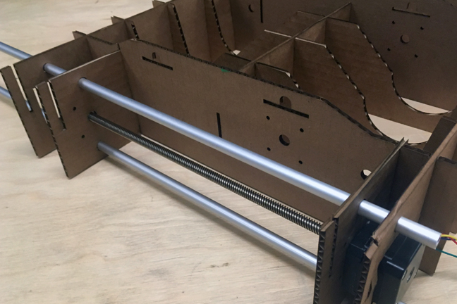
Prototyping Structure : second version.
The second and third cardboard prototypes evaluated strength of a press-fit body and included structures to mount the linear drivers and rods. This is taking more from Nadya Peek's design but building it into a body as opposed to her modular design.
All of our machine body prototypes were first modeled in Fusion. This makes the iterative process much easier. We were able to move farily quickly between the different versions.
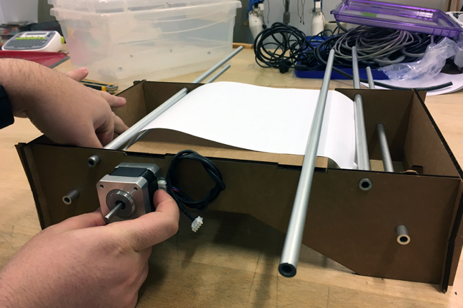
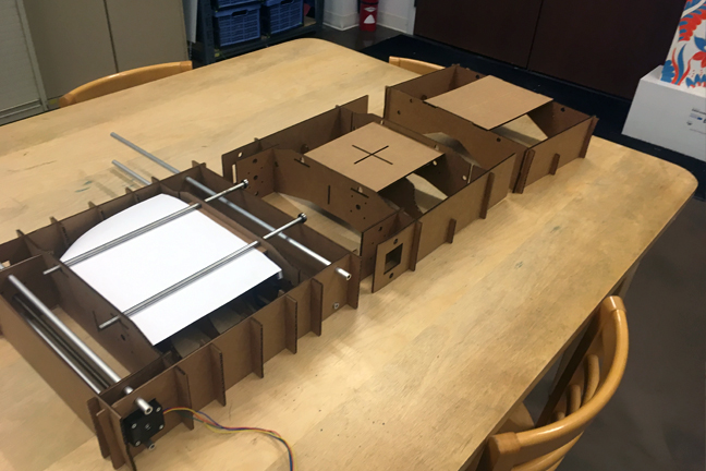
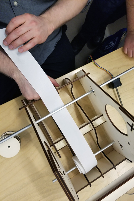
After three cardboard prototypes our ideas became more clear. The final cardboard prototype demonstrated the best press-fit system for strength but we needed to change the design so that the x-axis driver would be mounted above the paper rather than beside it as seen in the above image. We moved away from the idea of using a belt system for the paper feeding mechanism and chose to use the same motor that will be used in the x-axis. We also played with rods to see how best to keep the paper in place. The rod has to be heavy enough to pinch the paper onto feeding wheels that still needed to be built. We were confident that once the motor was in place, building the right size of wheel to feed the paper through was relatively easy.

Prototyping Structure : final version
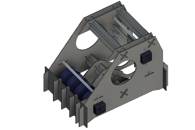
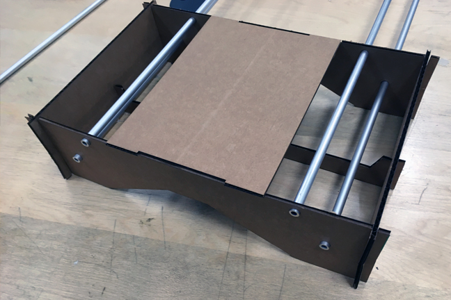
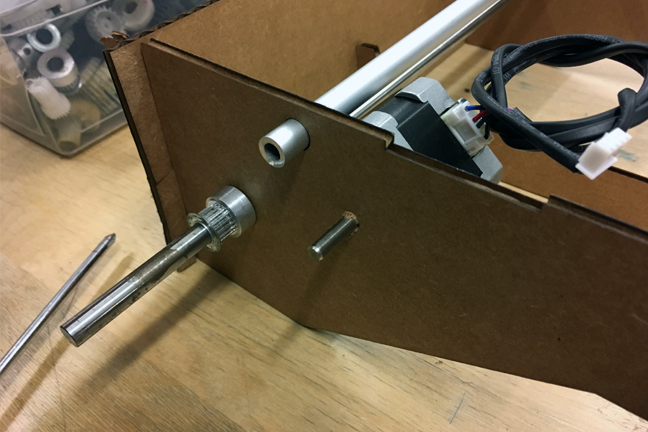
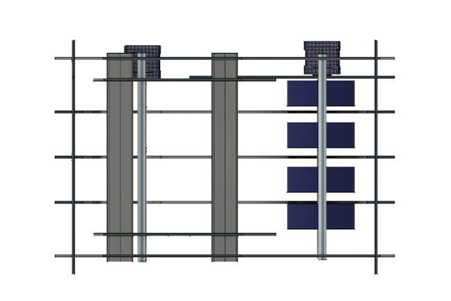
Time was of the essence. We were falling a bit behind schedule so the carboard testing quickly turned into final prototyping phase. The images below demonstrate a move to build the x-axis over the base. Press fit cross braces were used because of their lateral strength.
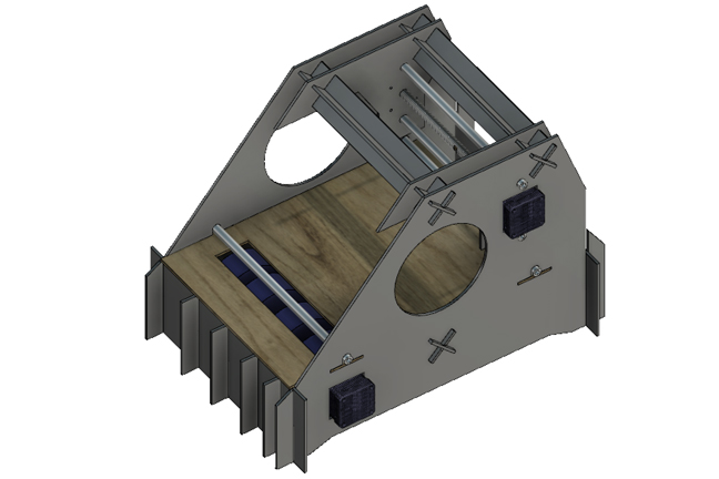
The Nema17 motors were mounted into the frame of the machine. Extra spacers were added to ensure a tight fit. Everything was designed with press-fit in mind. The only fasteners used are the M3 screws securing the motor to its brace. The feed system is design around a series of larger wheels. George had a great idea of making them out of silicon but we opted for a quicker solution of using gasgets that were already available.
Prototyping the Pen Holder Effector and Controler Box
To build the pen holder effector we used all the available materials and resources that we had at our FABLAB in order to speed up the process since we had a very tight deadline. Our initial idea was to design and make a funnel system that drop ink along with glue on the rolling paper but after a long discussion we all agreed on using a sharpie pen. Build a the Pen Holder effector was a better choice since it would be less messy and things would be much more controllable with using pen
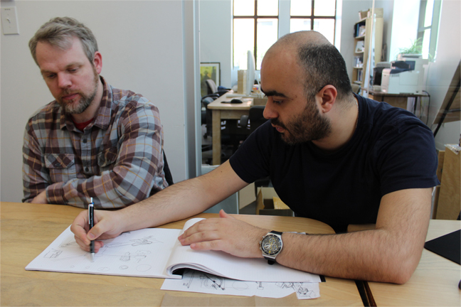
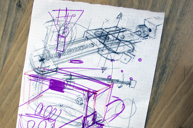
Based on that first we started sketching out the idea and George took the responsibility of building the Pen Holder Effector.
Building the Z axis was a really challenging process, the first change was making the whole part slide freely without any liner bearing and the 2nd change was moving the Z axis down and up without using a lead screw.
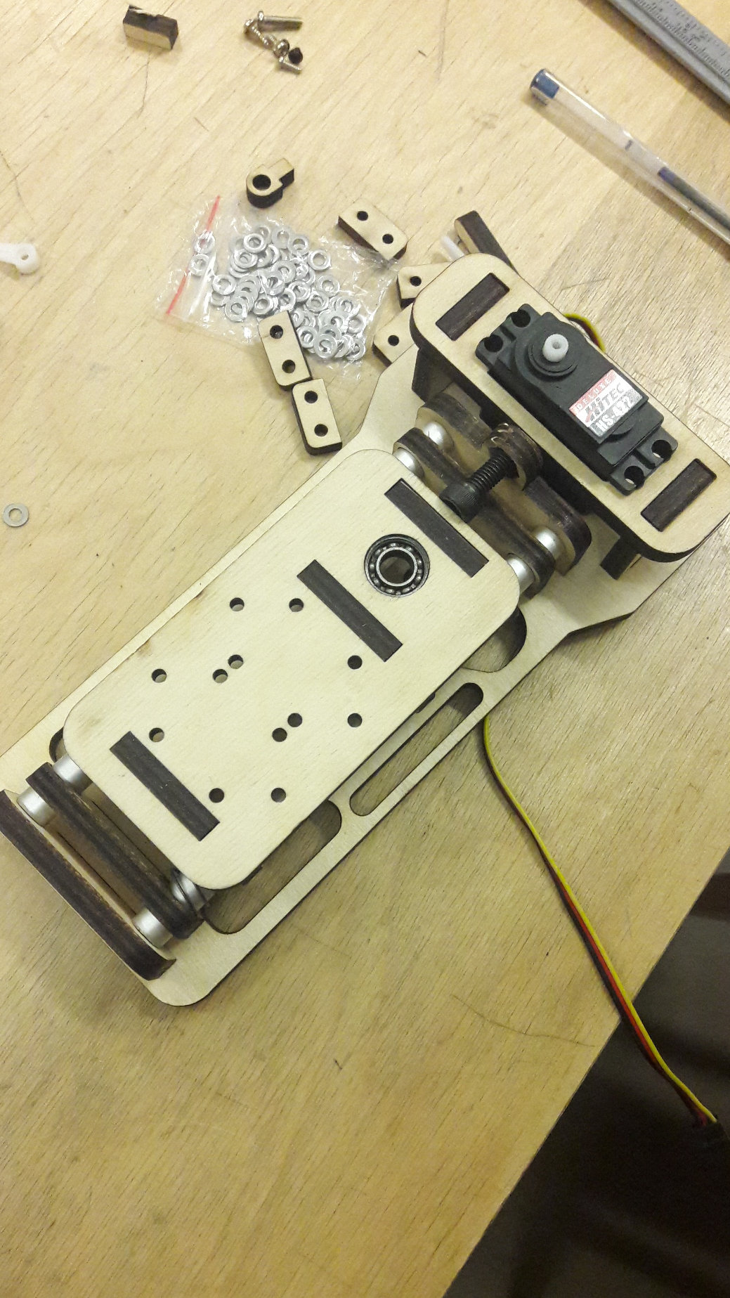
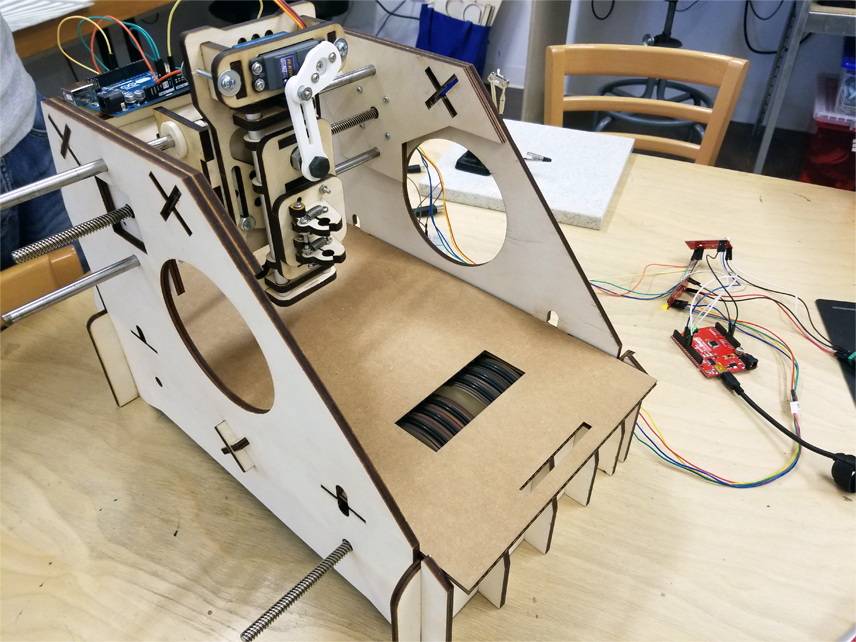
To solve these challenges we decided to use a servo motor for pushing the pen down and up and in order to convert the rotational movement of the servo to linear movement. We used a linkage mechanism. Initially, we placed the servo on the left side on the pen holder as shown in Figure 17 and 18, but after that we found that it was not a good idea to place it on the side because it will limit the X Axis travel distance. That’s why we decided to position the servo directly above the pen.
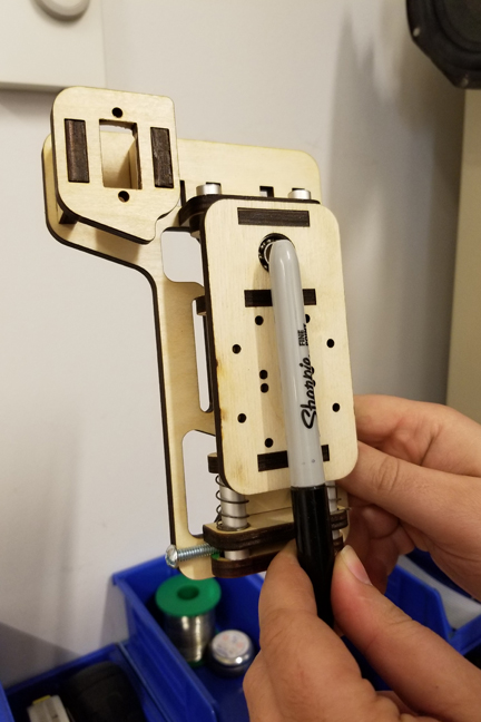
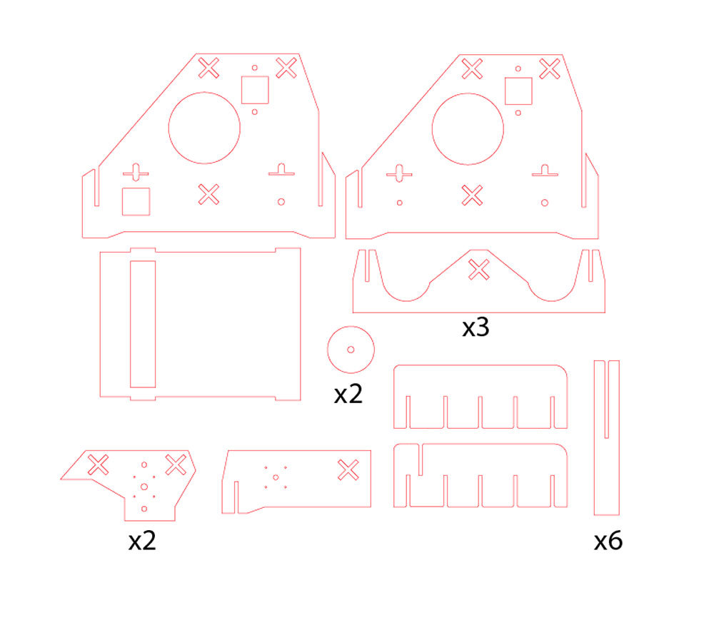
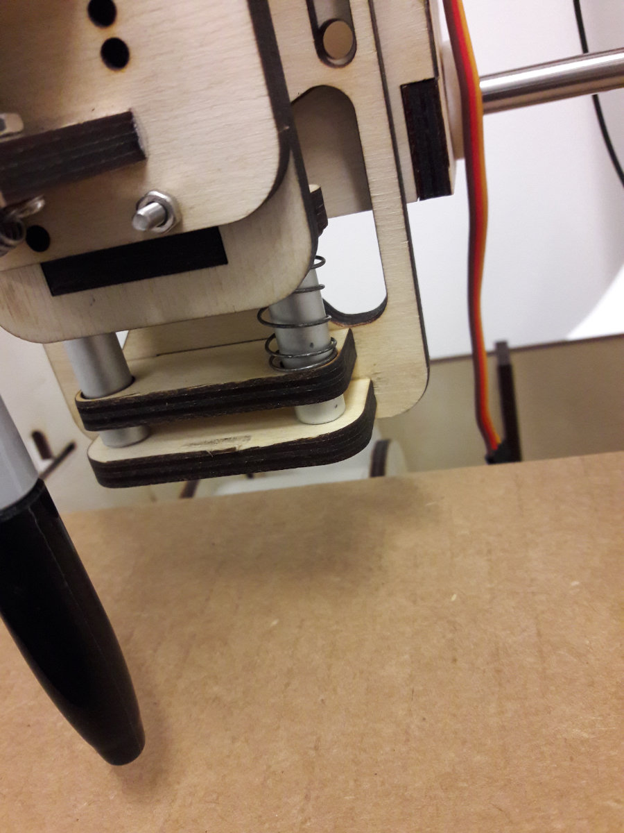
The linkages were made out of acrylic sheet and for making them we used the laser cutter machine. As for making the whole pen holder travel down and up smoothly along the Z Axis without using any plastic spacers, we used 2 aluminum pipes along with 3 wooden parts that were positioned and aligned vertically precisely. This mechanism helped us a lot with reducing the friction. As a result, it was easy for the servo to push and pull the whole structure. In addition to that, and in order to make the pen flexible when pushing down, we decided to use a metal spring which was positioned directly on the lower part of the pen holder as shown in the following Figure 20.
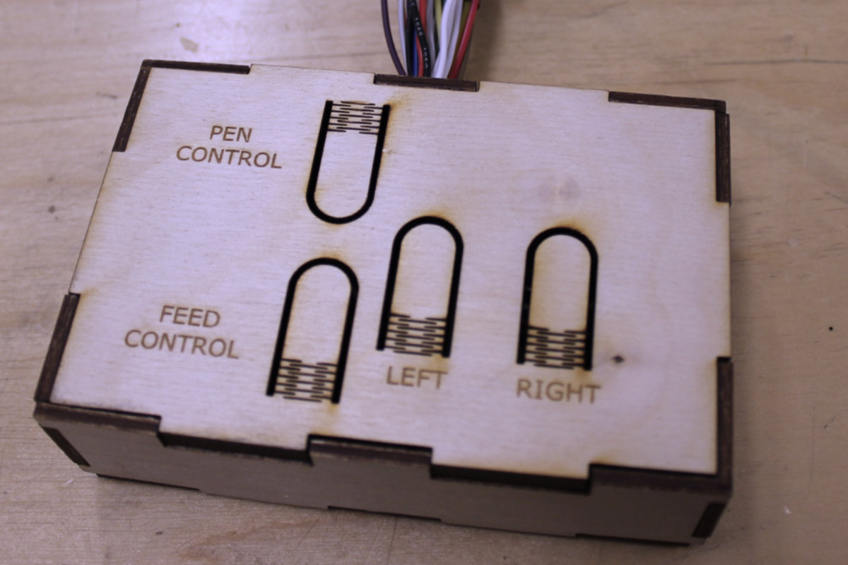
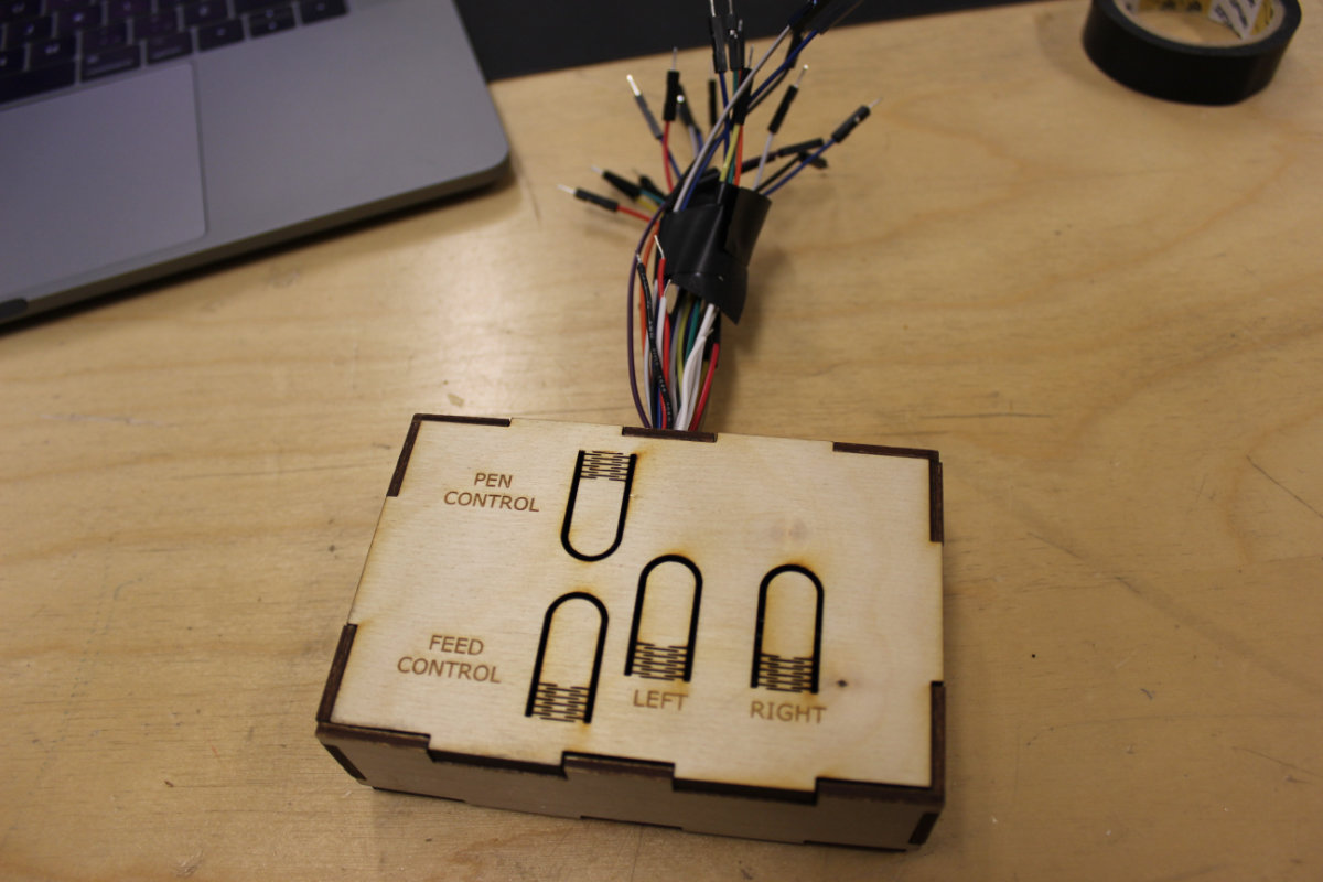
After that we had to assemble all the parts together and attach the Pen Holder Effector to the machine’s X Axis. The X Axis movement was fully controlled by a lead screw which was connected to a stepper motor. Beside working on the pen holder effector, George also worked on the remote control console for our machine. He used press fitted joints for joining the wooden parts together. For making the buttons, he used kerf bending technique for making the wooden buttons fixable and functional at the same time (See Figure 20).
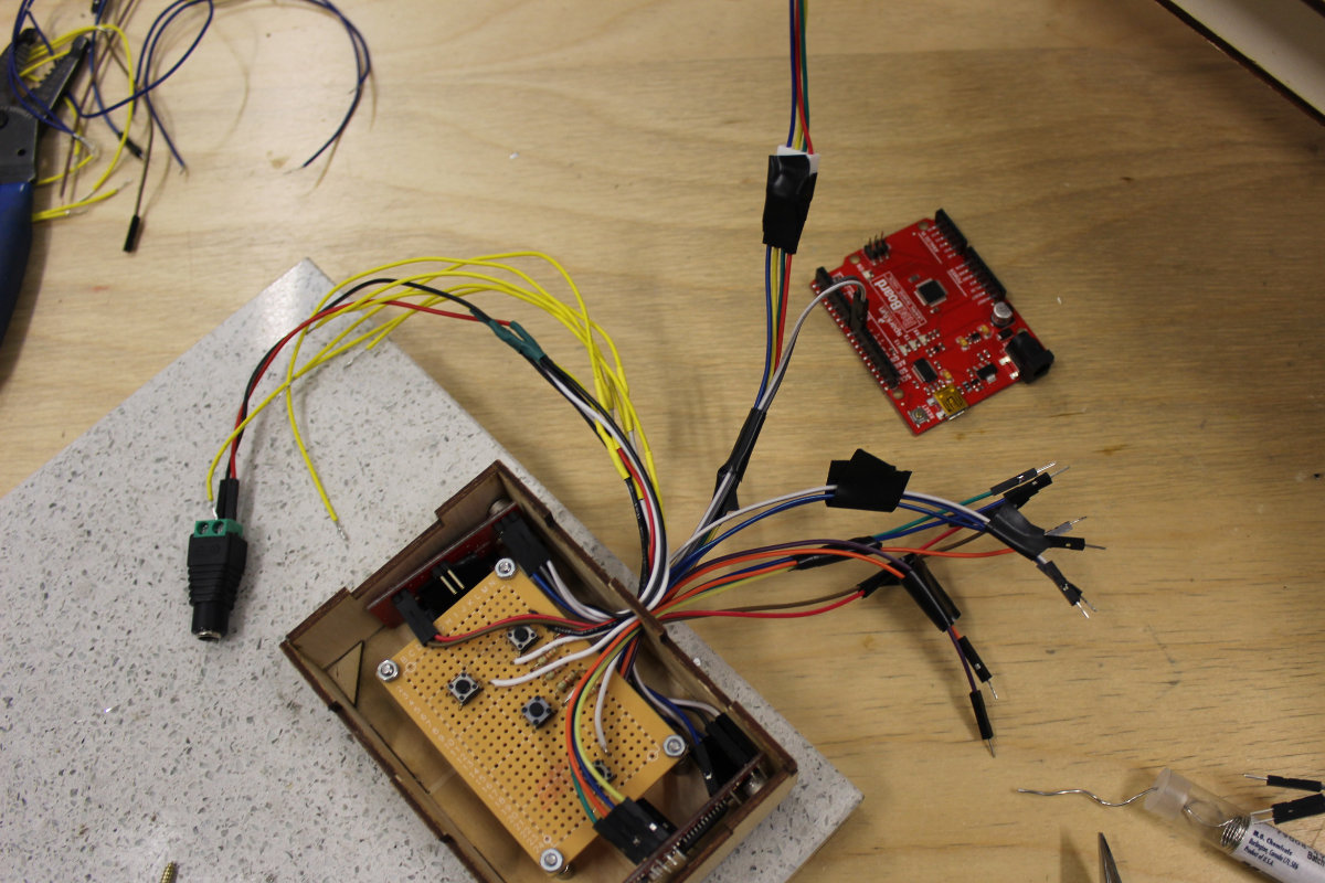
Electronics
While exchanging ideas for motorizing the machine, Mathieu gave me a circuit board telling me to check up on this one. I asked some questions about it and he told me that this was a Gestalt Node that can control a stepper motor. What's more, we had a kit comprised of three stepper motors with a long mechanical screw. My first discovery was Fab Academy website that gave the impression that this board was lacking in support. After talking about this problem, I was told that there was some doc and I redoubled my effort to find some and started to get some nuggets about this system. The main problem is the the GitHub depot where the code is, has a link to a website that says that it will be available in November 2013. Also, you get a link to a master's dissertation! Not a good start. I eventually understood that this dissertation is important and is required reading.
But once I started to use the author's name, Nadya Peek, I started to get more and more useful links that I put in here. So yes, it looks like there's information on how to use Gestalt Nodes but it is scatterred everywhere and there's no central repo to help people get started. I hope that this site will be helpful.
Gestald Node
The main advantage is that this system was designed for rapid prototyping with simplicity in mind: the use of cardboard for making the frame, a stepper motor, a screw, two guides and create a motorized module. One module can be added to the next and the motors are daisy chained to the next. But there's a two problems: first, the rotary stage, considered important by the author, has no page reference. This module is important to our concept (or other projects). Also, the dropbox containing the cut files refered to in the [m]MTM website is now a 404. I guess we'll have to make do with the motors.
This is a very interesting concept and let's see where this will led us to.
The building of the linear stage
As I came at the lab, Alec had cutted the file for the linear stage. With an X-acto knife I carefully removed the part from the cardboard. Alec warned me that the original file were not to scale and he had to guesstimate the scale. I started to make the assembly and eventually came up to a wall: the parts don't fit together. I tried with many configuration but whatever I do, the holes for the aluminium and the motorized shaft don't align. We'll have to fix this.

Fabnet
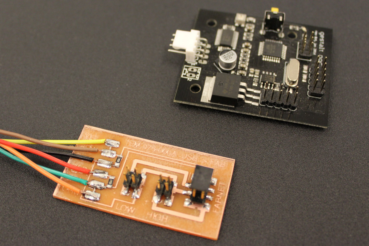
My first task is to get the node working. I carefully read the documentation and found that I need a module that connect the computer to the first node. I found this module at the Fab in a box website. It's a small module that uses a FTDI connector but the order of the wires are mixed up. Since we had FTDI cables with the connector, I was a little uneasy about cutting that connector for the Fabnet board and limit the usage of the FTDI wire exclusively to the Fabnet board. Mathieu came up with the idea of soldering jumper wires (with appropriate colored wires I might add) to the board instead and having the best of both world... I should have thought about that!
Since the mill was configured for pcb, I prepped a copper board and put it in place. I picked up the Fabnet trace from the website and push it to fabmodule. As my previous job, I configured the cut speed to 6mm/sec and, for once, put a -1 to get a clean board. The time to get it done was estimated at about 35 minutes.
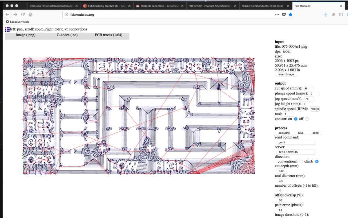
The board was done with no problem and came out really nice.
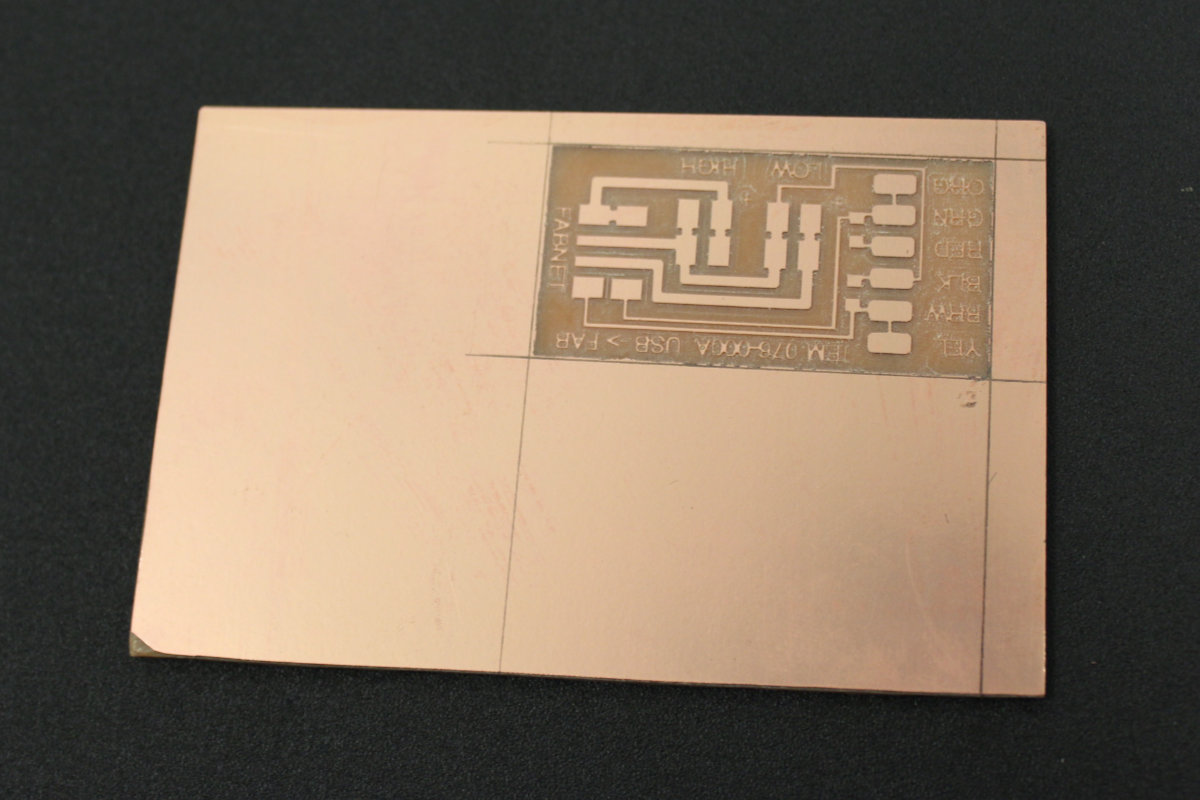
The soldering is really simple; two resistors plus the six wires to solder. I almost lost the board when I tried to solder the first wire: somehow, the solder did't stick to it. Try as I might, I couldn't get it done. As a solution, I decide to change the wire because cutting it down implied to cut all the others in order to have the same lenght. I did it just in time because the copper pad was starting to peel off the base. The other wires were easy to do as the header pins.
The problem with the transformer
Since I need some electrical juice to power the modules and the motors, I need a separate power source to feed the Fabnet module. I found a 7.5 DC transformer in the bin cut the adapter and for the heck of it, measured the voltage and be sure of the polarity of the wire -before- soldering the connector wires. To my surprise, the reading came out at 11.9 volts! Way too high. I went back to the box because there was another transformer without any purpose in life, this one universal. At 7.5 volt setting, the voltage reading was at 11.4! I checked all the different voltage but they were all off the scale. My investigation was interrupted because of a meeting with my regional mentor. As he told me, one strange reading is ok, but two, you'de be better off checking your instrument. Indeed. Next step, I will check the instrument with the regulated DC power transformer that we have at the lab.
The problem with the cable
During the meeting with my regional mentor, he pointed out that the first ribbon connector had two switchover cable that must be configured. Since this one is not documented, I ask questions about where I should get the schematic but no one was able to answer me. Eventually, I found the answer by myself.
The problem of scattered documentation
After reading Getting Started with Gestald Nodes, I found out that those problems might not be problems after all. The 11.4 volt output is really near the recommended 12V needed for driving the stepper motors. In the same web page, we find the documentation related for the connection between Fabnet and the first Gestald Node. Although I read about Bas's board, I didn't quite understood the need of it until I learn that I must reverse some wires between Fabnet and the first node. Bas's board eliminates this problem.
Gestald Nodes really need a central deposit for documentation to help users and future fab academicians alike.
Configuring the first node
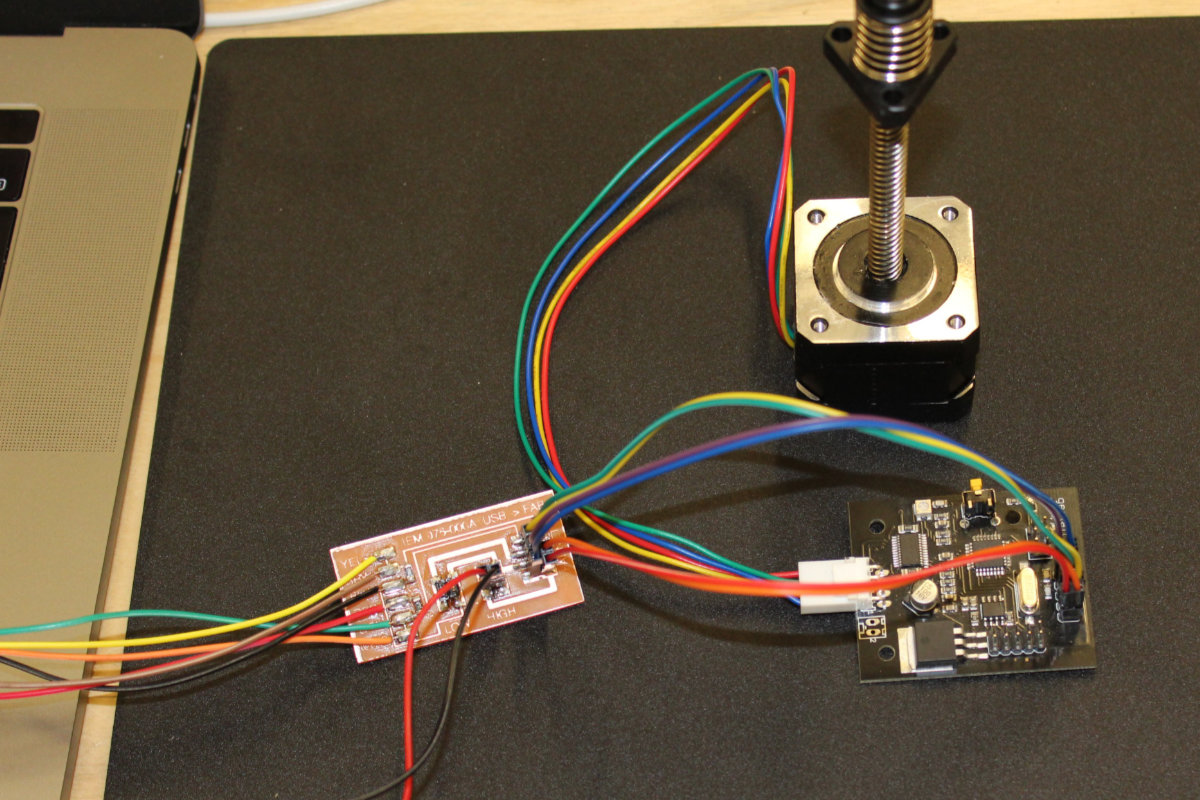
As I noted earlier, the first thing that I done when I went back to the lab was checking the multimeter that I was using against a regulated power supply. The reading were correct so it was the transformer that is giving out more juice than the specs printed on the power supply. But this voltage was what I needed so I went along, soldered the tips of the wires with connectors and added heat shrinks tube to go over the solder contacts once this is done. I no longer use electrical tape to do this. I've learned my lesson the hard way.
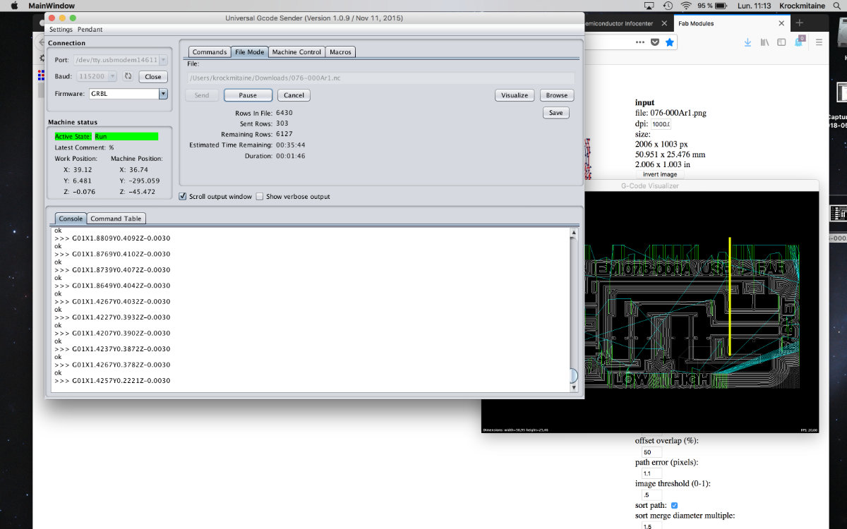
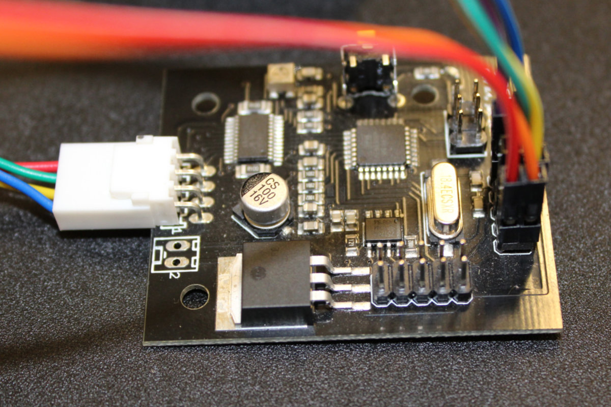
Once this was done, everything was set to power up the Gestald Node. Since I didn't had accesss to ribbon cable, I picked up connector cables instead. Before lunch, I made an initial setup with no power. When I came back I carefully checked the wiring and correct a misconnection that I made. Once this was done. I check again and finally powered my setup. Contrary to what was expected, nothing happened, no led blinked to acknoledge that it was under tension. Since it was a test, I turned off the power supply and then installed the necessary software. I followed the instructions given in the Getting Started With Gestald Nodes page. I installed the Pygestalt, edited the singlenode.py file with my device ID. I powered the GNode again, typed python singlenode.py and nothing happened. Next I read that I needed the pyserial, I followed the instructions and the install went smoothly. So now at last I had everything. I powered the board, typed in python singlenode.py again. The terminal sended me the following message:
FABNET: error opening serial port /dev/tty.usbserial-FT90ZRJN
FABNET: serialInterface is not connected.serialInterface in not connected message at the terminal. I talked with Mathieu about all my verification process, the fact that the led never lighted up, and we came to the same conclusion: the Gestalt Node board was dead.
Time to move on
Since the Gestalt Nodes order haven't yet arrived, it was obvious that we had to come up with a fast solution for our machine otherwise we would not make it for the deadline. I went to the more familiar Arduino territory. Alec had been investigating it and he sended some tutorial about configuring an Arduino board with stepper motors. What's more, he came up with the EasyDrivers modules at the right time. I started out doing the tutorials on the Easy Drivers Exemples page and familiarized myself with the steppers, basic with one motor setup followed by two motors setup with homing switch. Those tutorial went with no problems as they are really well made. I made a first setup with one motor by following the How to set the HOME position of a Stepper at Startup! at the Brainy Bits web page. Once tested, I added the connection for the Servo Motor controlling the effector that George made.
So I was now with two Arduino boards with plenty of pins. I decided to go overboard and integrate all the pins into one board and one sketch. But this plan didn't go as smoothly as I tought. Integrating was starting to get too much of my time and Alec reminded me gently to eliminate all layers of complexity. As it was getting late, I was tired and took his advice. I dismantle all that I've done so far and went back to my initial, and working, two boards setup.
Integrating the interface
After all this exhausting work, there still remain the task of integrating all those wires into a neat box designed by George. While I left at the end of a long day, Alec and George stayed a while and finished the machine and made tests and it was functionning as intended.
That task would normally be an easy one for me as I've done this many times over. But I was tired and exhausted. During the whole integration process, I was always concerned not to do any damage to the program or the machine.
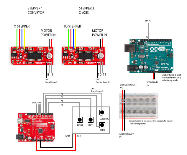
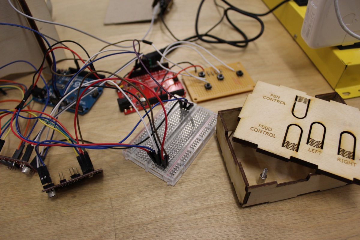
I started by getting myself acquainted with the setup and expecially the box. I wasn't even sure that everything would fit inside. I had to put the board with the buttons in the box and level it so the buttons on the cover would activate the buttons. I eventually found an box full of nuts a picked up 8 M3 nuts. I measured an ideal height for the board (5mm) with a caliper and locked the lower nuts with glue. I put the board and put 4 nuts on top so vibrations don't get the board out of alignment. Once done, I delicately put the two EasyDriver on both sides of the board and made sure that all would fit with the cover in place. It did. So I removed the cover, then the board and the drivers. I then enlarge the hole to make place for all the connecting wires that I will have to fit inside.
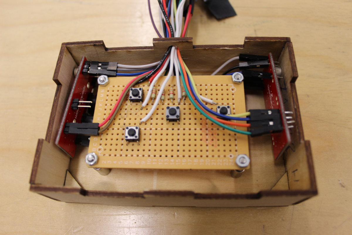
I would really worry about using such an enclosure as the drivers generates lots of heat, and we're using 5 volts to feed the motor. For normal operation, this box is in need for ventilation holes to dissipates the heat. But since this is a prototype, it's not a concern and it will do a nice job with it's expected operating parameters.
Once this was done, it was time to solder extention wires to the shortest wires so I can connect them to the Arduino.
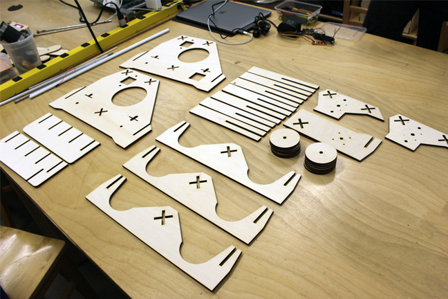
3. Production
After many prototypes, it was time to laser cut the parts for the machine.
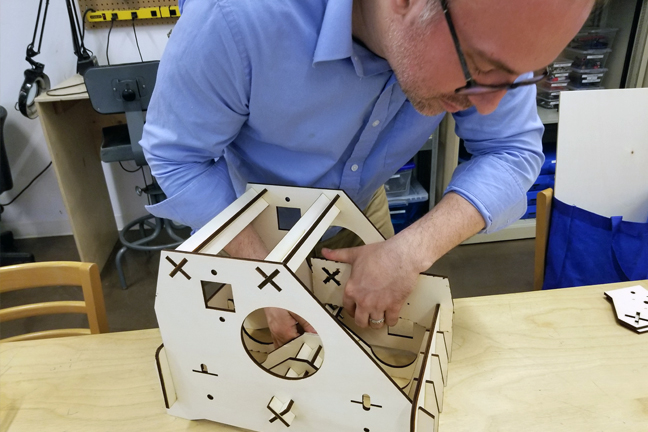
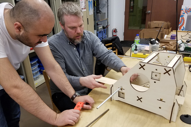
Frame Assembly
Video 1: Testing the paper feed manually
Video 2: The first time the machine was powered with all the motors
Video 3: Testing the GAM control box buttons
Video 4: Programming the machine with the pen marker.
4. Demonstration
Final version
The final version of our machine
5. The Team
The team was initialy composed of four Fab Academician students. Due to health reasons, one member of our team (Geoffroi Garon-Épaule) wasn't able to fully participate on this assignment.
- Geoffroi Garon-Épaule:
- Contributed the initial draft of this document.
- Georges Hanna:
- Contributed the desing and construction of the pen effector plus the control box.
- Marc Lemaire
- Contributed the electronics and integration. Also completed the documentation and web development of this page.
- Alec Mathewson
- Contributed the desing, construction and testing of the machine.