BOARD #1
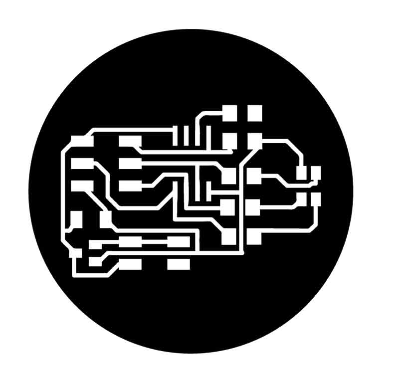
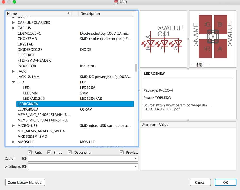
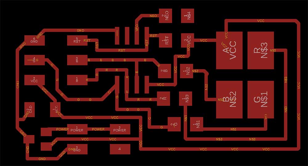
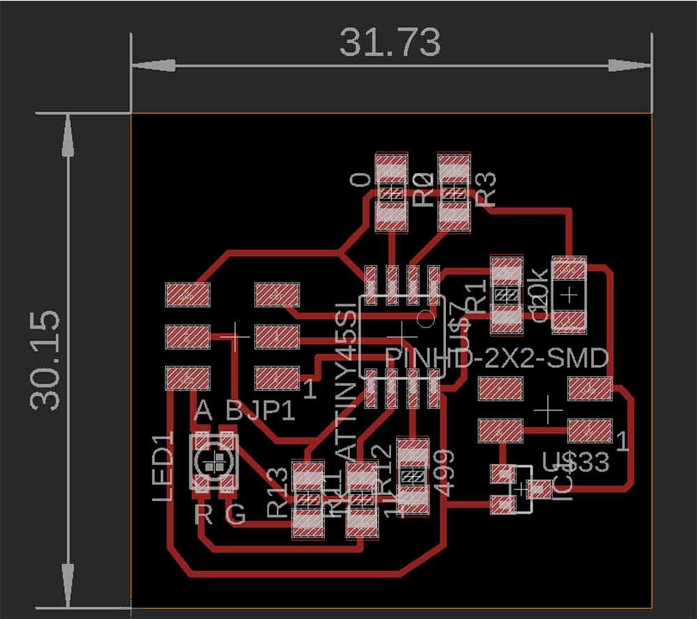
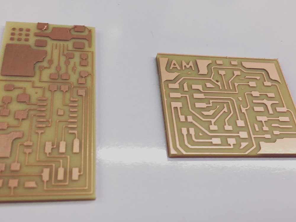
My first attempt was to start re-drawing Neil's example but adding extra pads for future use with NeoPixels. I wanted to understand the relationship between the components by re-drawing it in Eagle before designing a custom board.
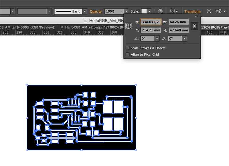
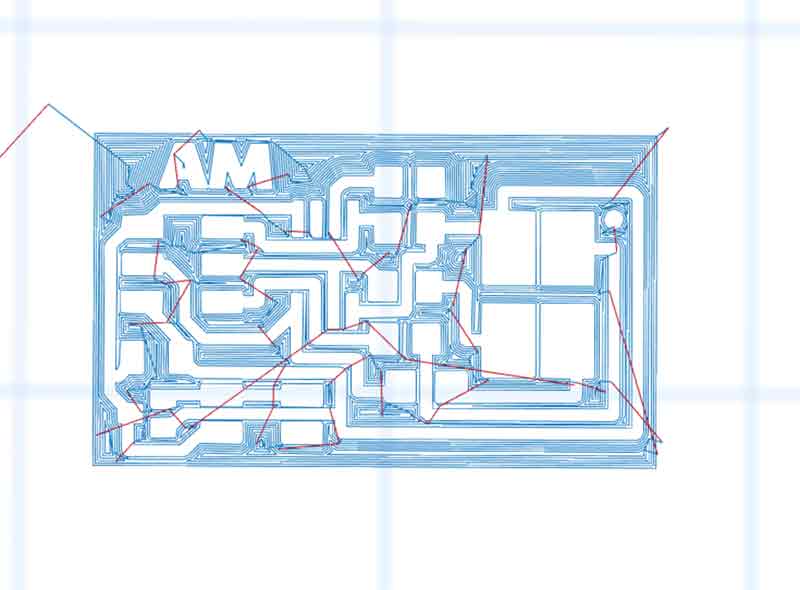
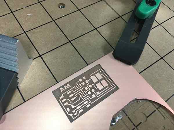
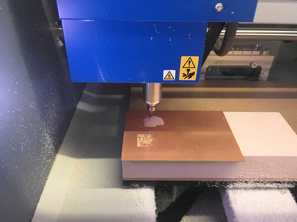
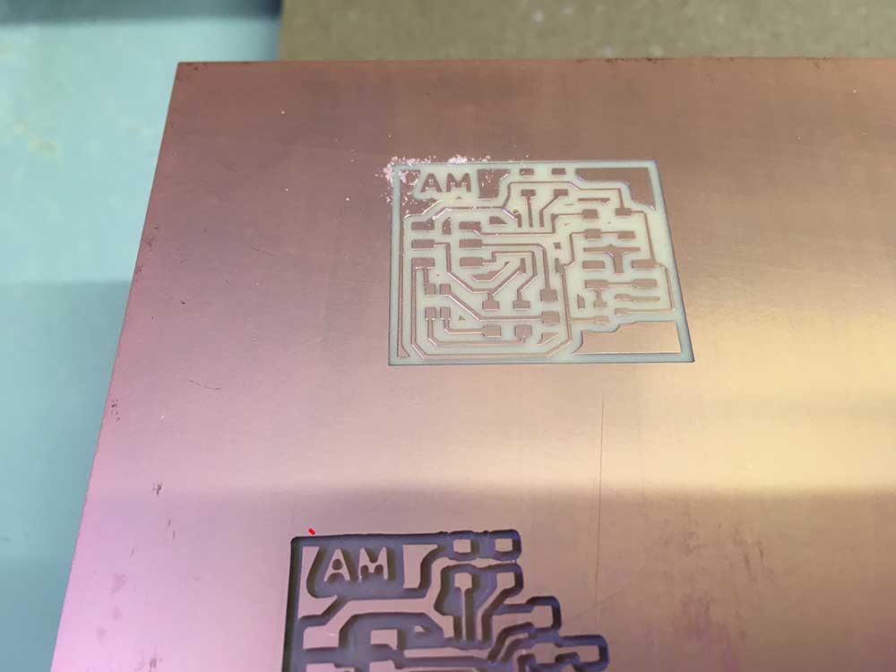
I was able to visit a local Fab Lab and had a chance to use their Roland MDX 50. I appreciated that you can home your z-axis with a homing sensor/puck anywhere on the plate. I definitely did not have the depth issues I have been experiencing with the Carvey.
---> Hello Frankenboard!!
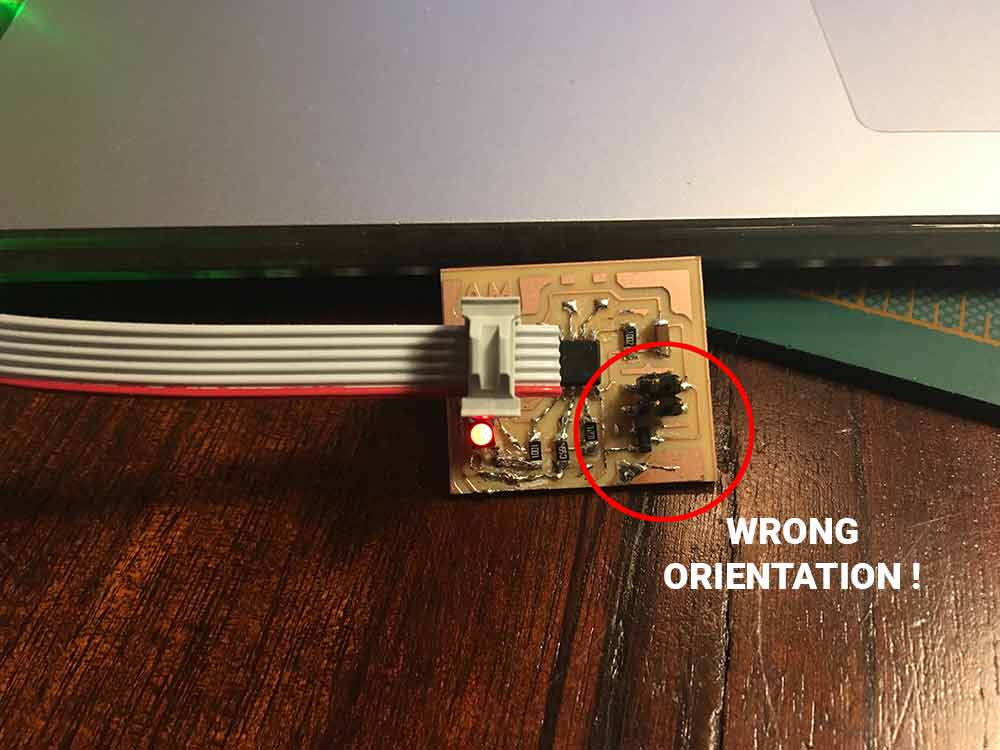
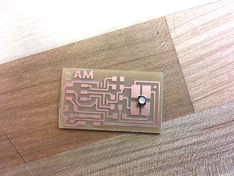
The following board is an example of what happens when you rush a process. Although I managed to salvage the board, the end result is a Frankenstein-like creation with several errors. This seems to be a common thread in my learning. I need to change a part and I end up with some monstrosity. I am sharing it with the world as opposed to tucking it away. I learned that these RGB LED's are a pain to solder and very easy to orient the wrong way. The part number for this specific LED is:
---> CLV1A-FKB-CK1N1G1BB7R4S3CT-ND
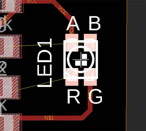
Like many components, the notch or the line usually identify cathode, or anode. For this LED it is R.
It is important to note that I was following the schematic and the layout of the part. If you look at the Eagle board above you will see that I matched the labeling. However, this LED is not the same. R is in where B is supposed to be.
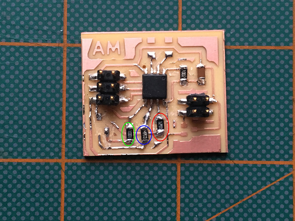
I started by reorganizing the resistors to match the new orientation.
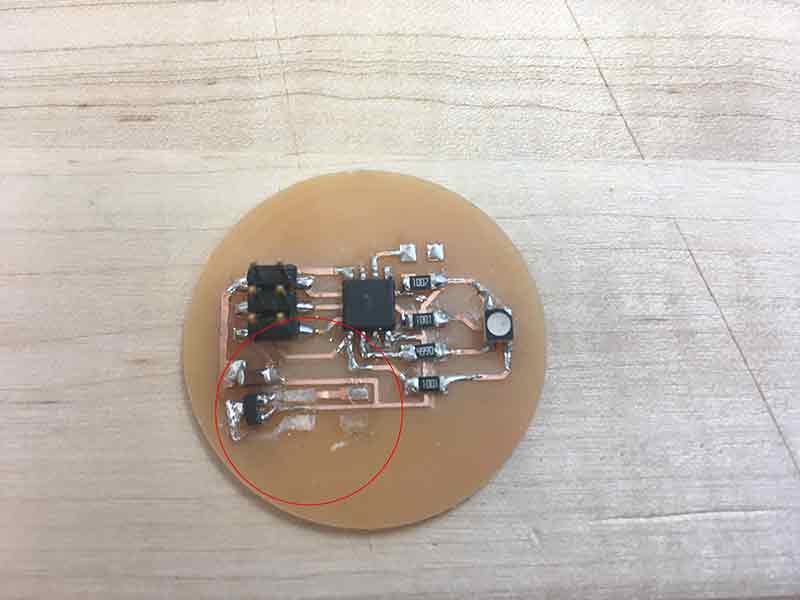
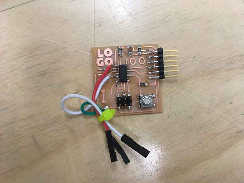
Traces were burning out on me. This board was cut with FR4 pcb material. We were careful with it and it was milled in the machine enclosure. It seemed that the traces burnt off more easily. Anyways, I had to get creative to find a solution to fix this problem so I started using wire and jumpers. I would suggest NOT to use braided copper wire. It is harder to work with and can get messy. There is always the chance that some strands of copper will stray away and create shorts.
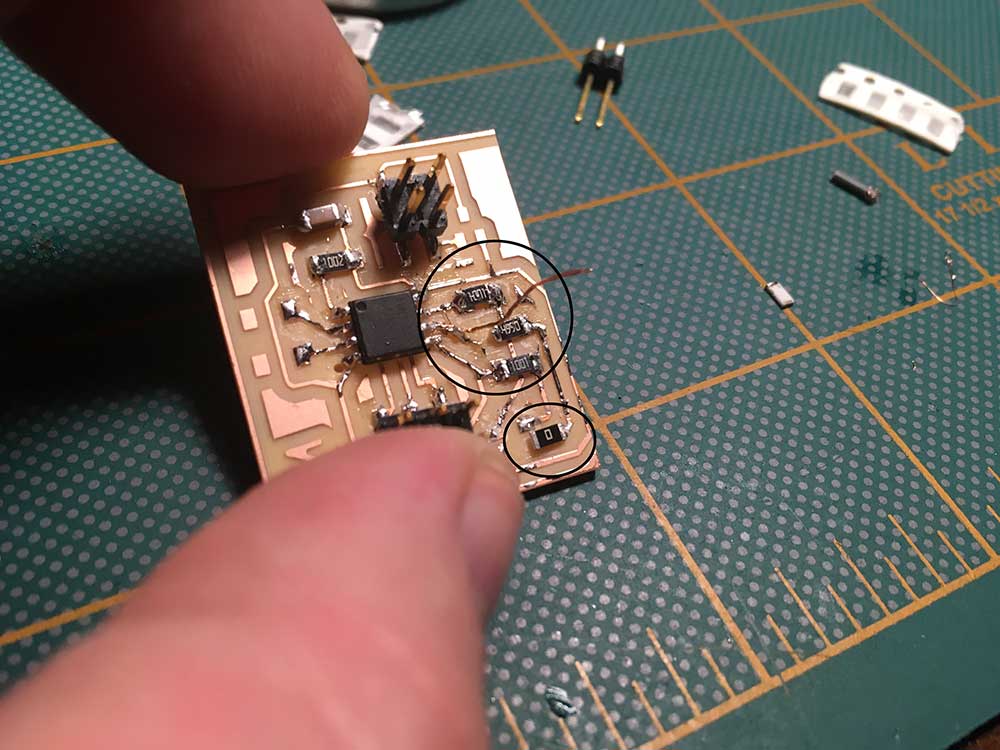
Tthe 1206 SMD 0 ohm jumpers were not going to work. I soldered wires to the bottom of the LED thinking this would make it easier.
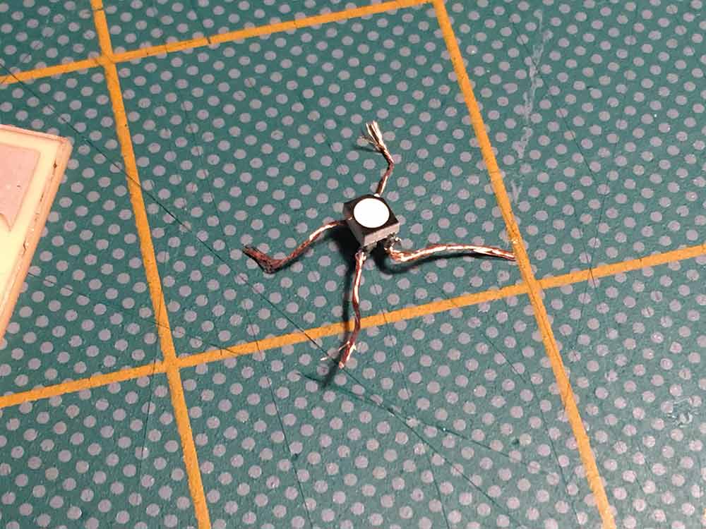
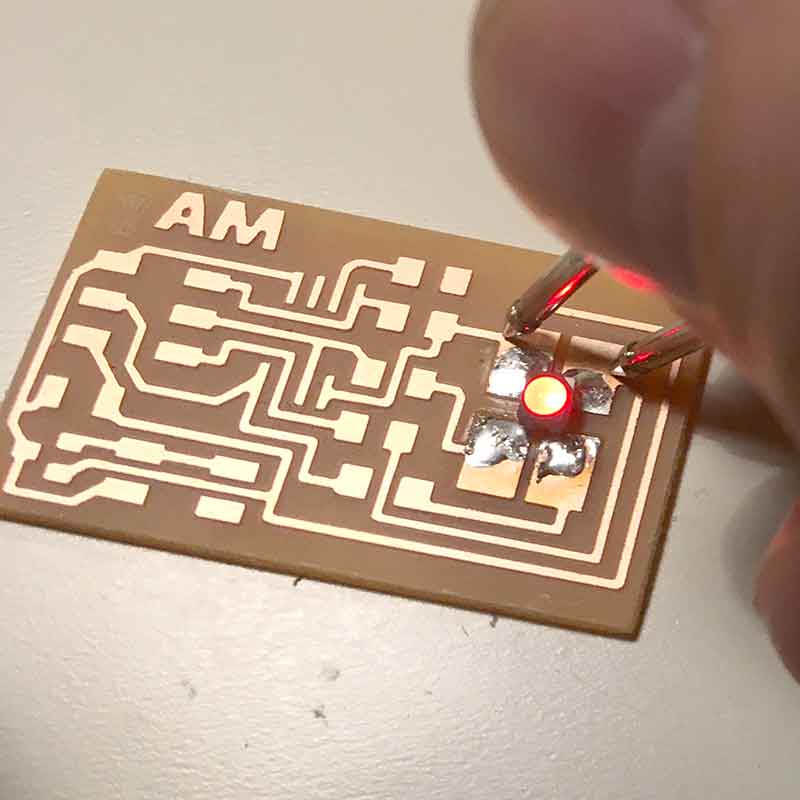
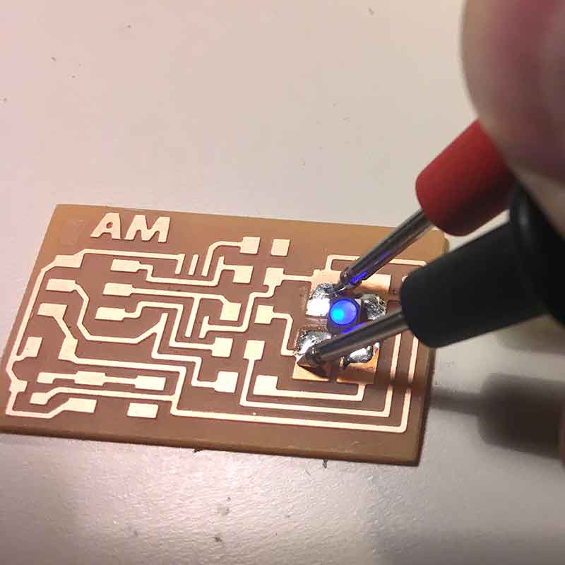
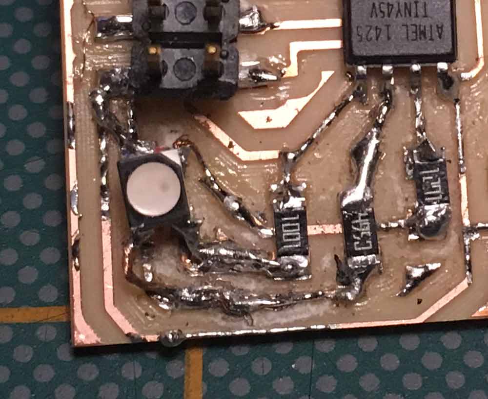
Wow! Look at this beuty! Enough said. But... it passed continuity tests.
Next I needed to program the board. I was more curious than anything to see if this thing would work. I attached my FabISP and loaded a sample code from Adafruit found HERE and then using the Arduino IDE I successfully uploaded the sketch using Sketch / Upload Using Programmer. I had to adjust the pins to match the ATTiny45 and I also had to add back the line #define COMMON_ANODE because the RGB LED I was using had a common anode and not a common cathode.
/*Modified from
Adafruit Arduino - Lesson 3. RGB LED
*/
int redPin = 2;
int bluePin = 1;
int greenPin = 0;
#define COMMON_ANODE
void setup()
{
pinMode(redPin, OUTPUT);
pinMode(greenPin, OUTPUT);
pinMode(bluePin, OUTPUT);
}
void loop()
{
setColor(0, 0, 255); // blue
delay(1000);
setColor(255, 255, 255); // white
delay(1000);
setColor(255, 0, 0); // red
delay(1000);
setColor(0, 0, 255); // blue
delay(1000);
setColor(80, 0, 80); // purple
delay(1000);
setColor(255, 255, 0); // yellow
delay(1000);
}
void setColor(int red, int green, int blue)
{
#ifdef COMMON_ANODE
red = 255 - red;
green = 255 - green;
blue = 255 - blue;
#endif
analogWrite(redPin, red);
analogWrite(greenPin, green);
analogWrite(bluePin, blue);
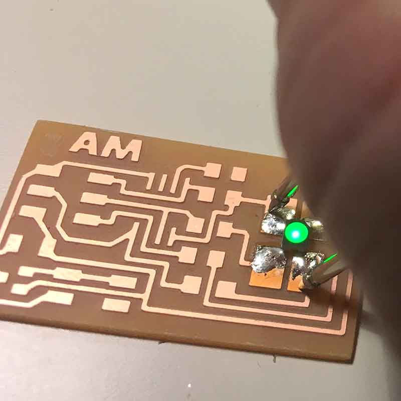
}The code seemed to work although it did not pass the smoke test. I started to smell burning.
---> failed smoke test
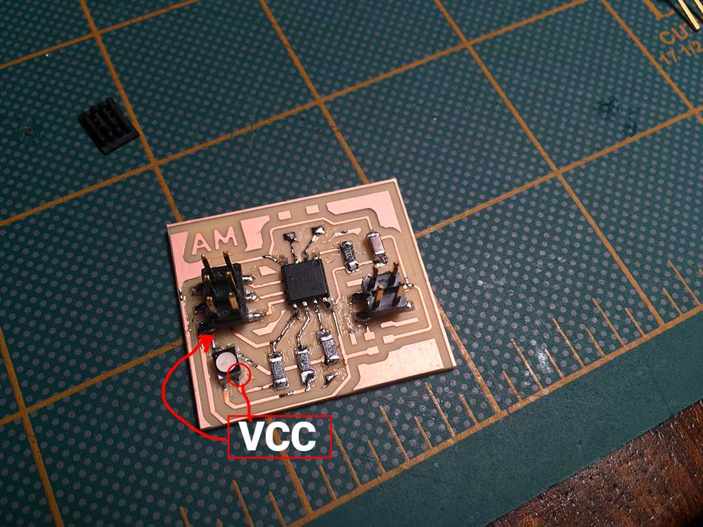
After all this work, when I plugged the board in with an external source there was smoke. Upon review, my voltage regulator was designed on the wrong side of the power input. This means unregulated power was going through the board. I have been pretty lucky in Fab Academy with my boards but today was not my day.