WEEK 13
INTERFACE & APPLICATION PROGRAMMING
ASSIGNMENT DETAILS: Write an application that interfaces with an input &/or output device that you made, comparing as many tool options as possible.
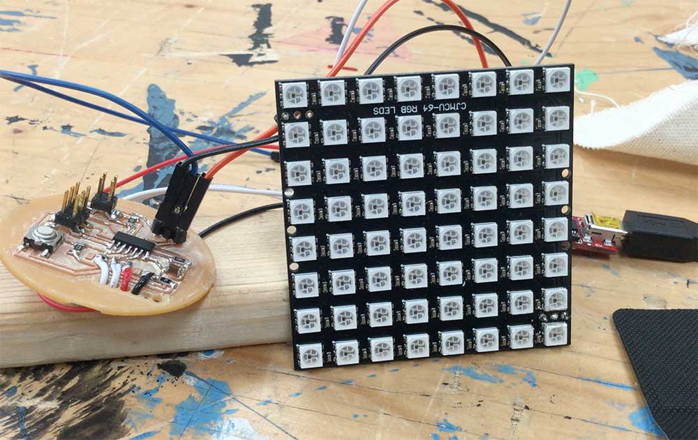
INTRODUCTION:For this week's assignment I wanted to see if I could interface Max MSP, one of my favorite tools, with a board I made running Logo. The setup consists of the following:
---> Circuit - Attiny84 with Logo bootloader installed
---> Output - 8x8 Neopixel Grid
---> Sparkfun FTDI Basic to communicate between board and CPU
---> Macbook pro running Max 7
LOGO
Once my board had the Logo bootloader installed and I was able to verify everything was working, it was time to install the program allowing me to communicate with Max.
--->
Instructions on installing Logo Bootloader on ATTiny84 board.
---> Installing the Logo Programmer
With the bootloader installed, I was now able to install Logo on my board. Here are the steps:
---> navigate to the folder logo-vm and open assemblar.jar
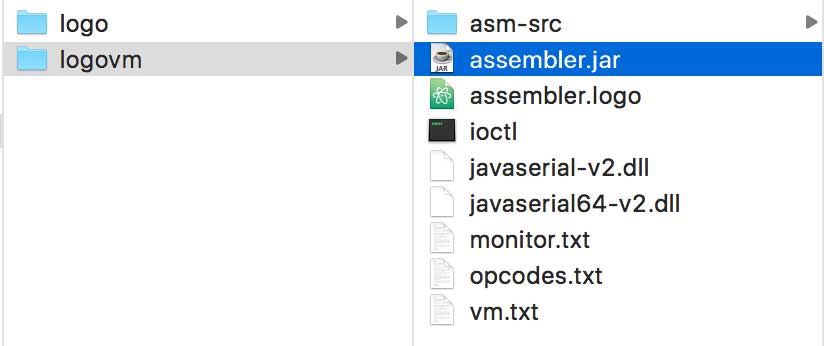
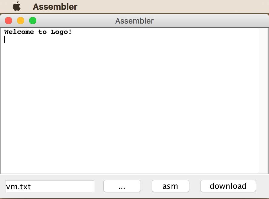
NOTE: assemblar.jar is a Java applet that lets you load the Logo interpreter on the ATTiny board. vm.txt contains the code that runs the interpreter and lets you code with Logo.
---> verify that the Logo bootloader is properly installed.
send $ff print recc
If successful, you will receive a return message 35 OK
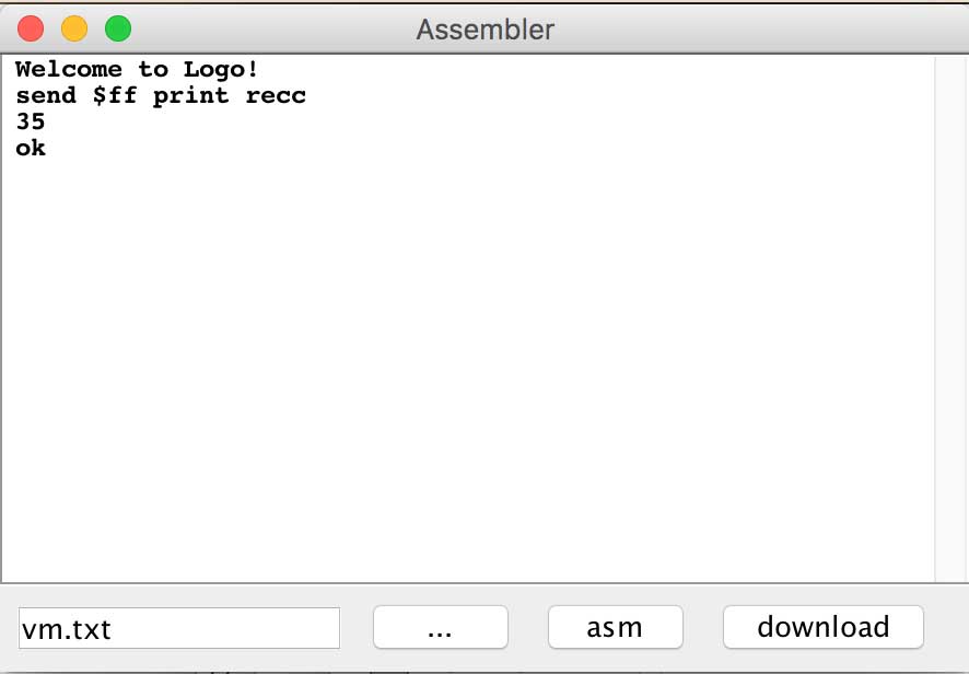
This is just a number that has been programmed to be the response. It is basically letting us know that we can communicate between Logo and the ATTiny.
---> Next, press the asm button. A number of words is reported back.
---> Next, press the download button. The RX/TX lights of the FTDI basic light up demonstrating that communication is established and that the logo programmer is being installed.
---> Quit assemblar.jar.
---> Programming With Logo
With the Logo programmer now installed on my board, I needed to check that Logo is ready. I followed these steps:
---> navigate to the folder logo and open Logo.jar
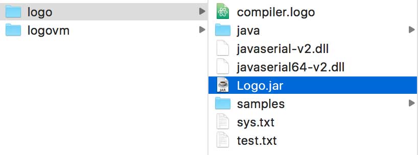
NOTE: Logo.jar is a Java applet that lets you load your Logo programs on the ATTiny board. You can insert commands and call up your custom programs directly in the programming window. Generally, you write your programs in a code/text editor and then call those programs here. The fun thing is you can test features of Logo directly to help teach you how different code works. I use Text Edit, formatted to work with plain text, to write my programs.
---> checking Logo
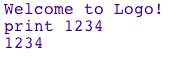
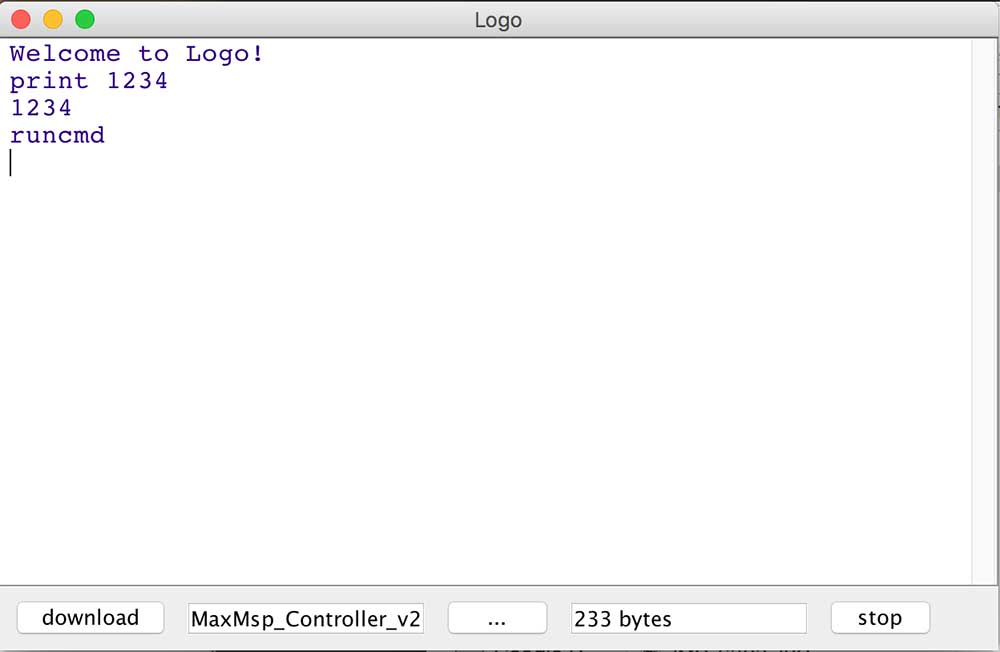
The first thing I did was to make sure Logo is working. In the Logo programmer window, type:
print 1234If successful, you will receive a return message 1234
---> playing with LED's
At this point, everything is working. It is time to play with the NeoPixel grid. I am simply using the Logo programmer to send messages directly to my ATTiny board which is connected to the LED grid which is assigned to pin PB3.
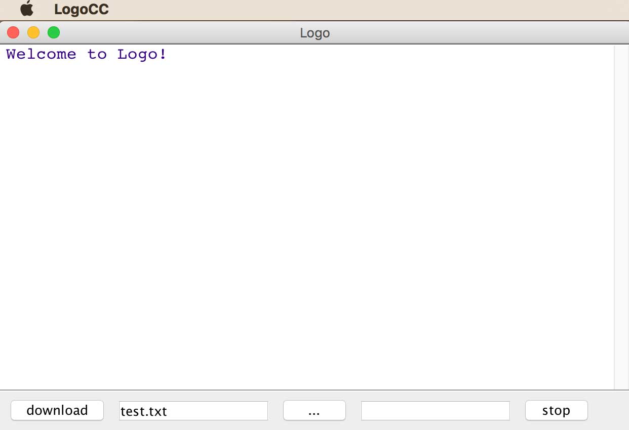
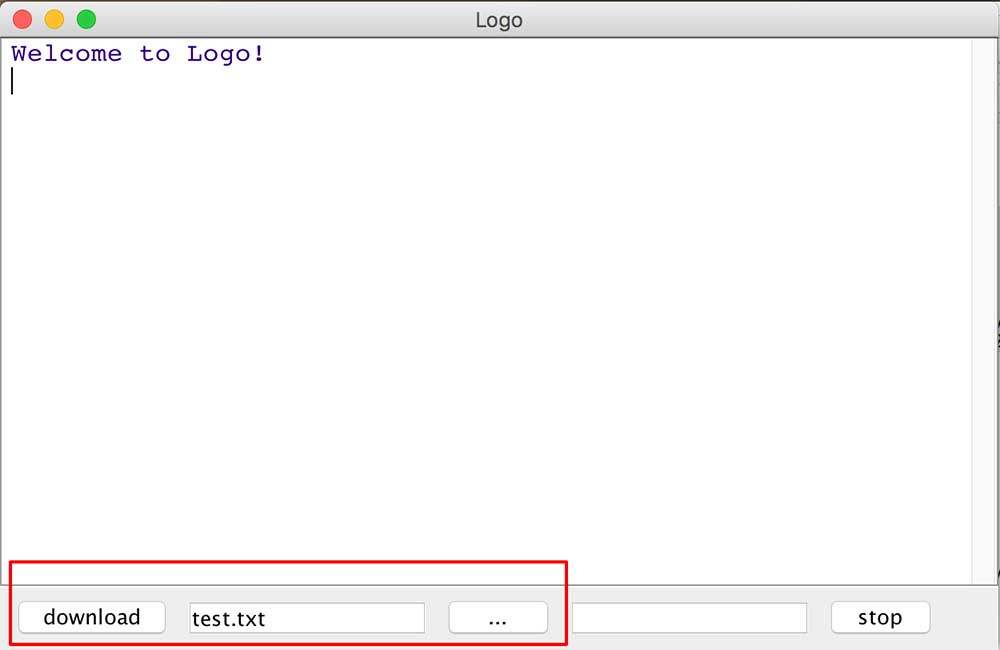
I next loaded a test program, test.txt, onto the board. To do this, I followed these steps:
---> press the "..." which lets me load a file in the Logo programmer
---> press download
NOTE: Once executed, the RX & TX lights on the FTDI board should blink.
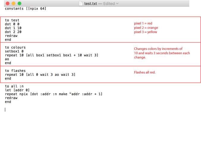
This is what was in the test.txt code.
constants [[npix 32]]

to all :n
let [addr 0]
repeat npix [dot :addr :n make "addr :addr + 1]
redraw
end

define ao [][alloff redraw]
Interpretations:
---> npix 32 = numper of LED's
---> to = create label for action
---> all :n = define the action as "all" with a variable
---> let [addr 0] = set LED address to 0 for off
---> repeat npix = repeat 32 times
---> [dot :addr :n make "addr :addr + 1] = turn the LED address from 0 to 1 or off to on and set the variable :n to the color value.
---> redraw = to execute
---> ao = calls alloff and execute
///// SIDE NOTE - UNDERSTANDING WHAT IS HAPPENING HERE /////
test.tx was the program I installed on the board allowing me to interface with LED matrix. To understand the lables that are not generated within test.txt, I need to refer to the vm.txt file. This is the main setup for the Logo interpreter. It is the base from which all the other functions come from and it contains lower level content dealing with the behavior of the ATTiny. For example: alloff in the vm.txt file that was loaded in the previous assemblar step looks and like:
prim-alloff
	[rcall clear-pixels]
	[rjmp poll]

clear-pixels
	[ldi x [byte0 :pixel-buf]][ldi xh [byte1 :pixel-buf]]
	[ldi y [byte0 192]][ldi yh [byte1 192]]
	[ldi d0 0]
Back to the Logo programmer. I started by calling the all command.
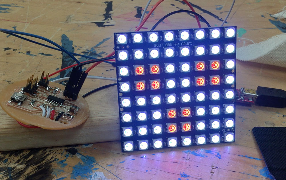
all 10This was supposed to make all the LED's orange. 10 is the number value attributed to orange Logo. Here is a reference to the different color codes.
Oops! I only got half the pixels lit.
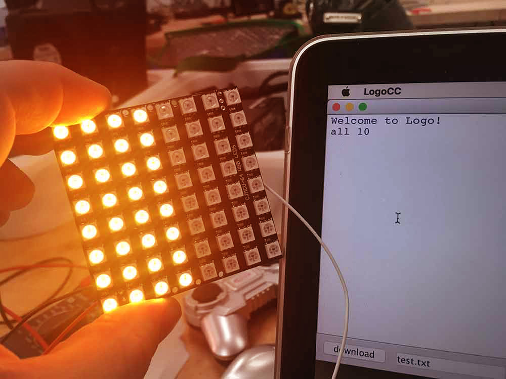
To turn off the LED's I typed in ao or "all off".
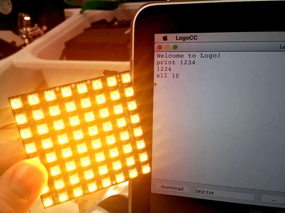
What I like about Logo is that it was fairly easy to fix. Referring back to the test.tx posted above constants [[npix 32] refers to the number of pixels. It is only set for 32. This is because the code was initially written for a 32 pixel string. Easy fix. Change constants to:
constants [[npix 64]]
Save the edited test.tx file press download in the Logo programmer. Watch the TX/RX lights blink. I tested logo again to make sure nothing broke by typing print 1234 and got my reply. I then typed all 10. Voila!
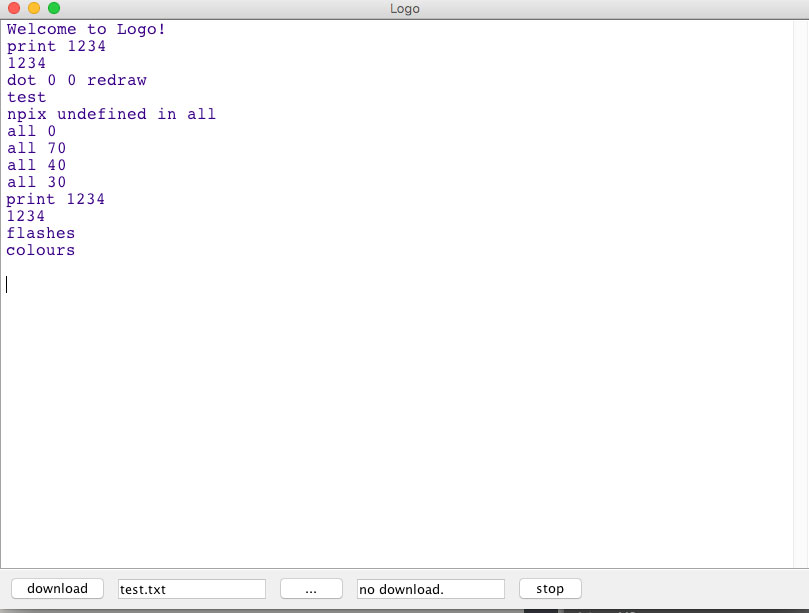
I added more code to the test file and played around with it. Super easy.
MAX MSP
I made an interface to control the 8x8 grid using MAX and Logo together. This was extremely exciting for me. I chose to use Max MSP / Jitter because it is a tool I am comfortable with but I am also interested in other platforms. With more time, I look forward to checking out Firefly.
Here is a video demonstrating what I ended up making. You can control each individual pixel and which color to choose from. There were 2 main steps I needed to do to make sure that Max and Logo communicate.
---> 1) set up a list of commands in Logo
---> 2) set up serial communication to the ATTiny from Max MSP
---> Logo commands
Logo commands will execute an action when a message is received. To turn NeoPixel on or off the code looks like this:
dot 2 10
redraw
This means LED 2 will turn on as orange. To set a command for this, the code looks more like this:
if cmmd = 2 [dot 2 10 redraw]
redraw
Now when Logo receives a value of 2 it will call the command and turn on pixel #2 as orange. To be able to change the color on the fly, I need to store a variable. In Logo this called a box. In this case, box1 is the container that the color value will be stored. So if I select red in max, box1 will turn to red.
Next I needed to map out the pixel numbers.
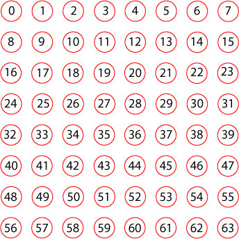
Now referring to this list of numbers, I was able to complete my list of commands.
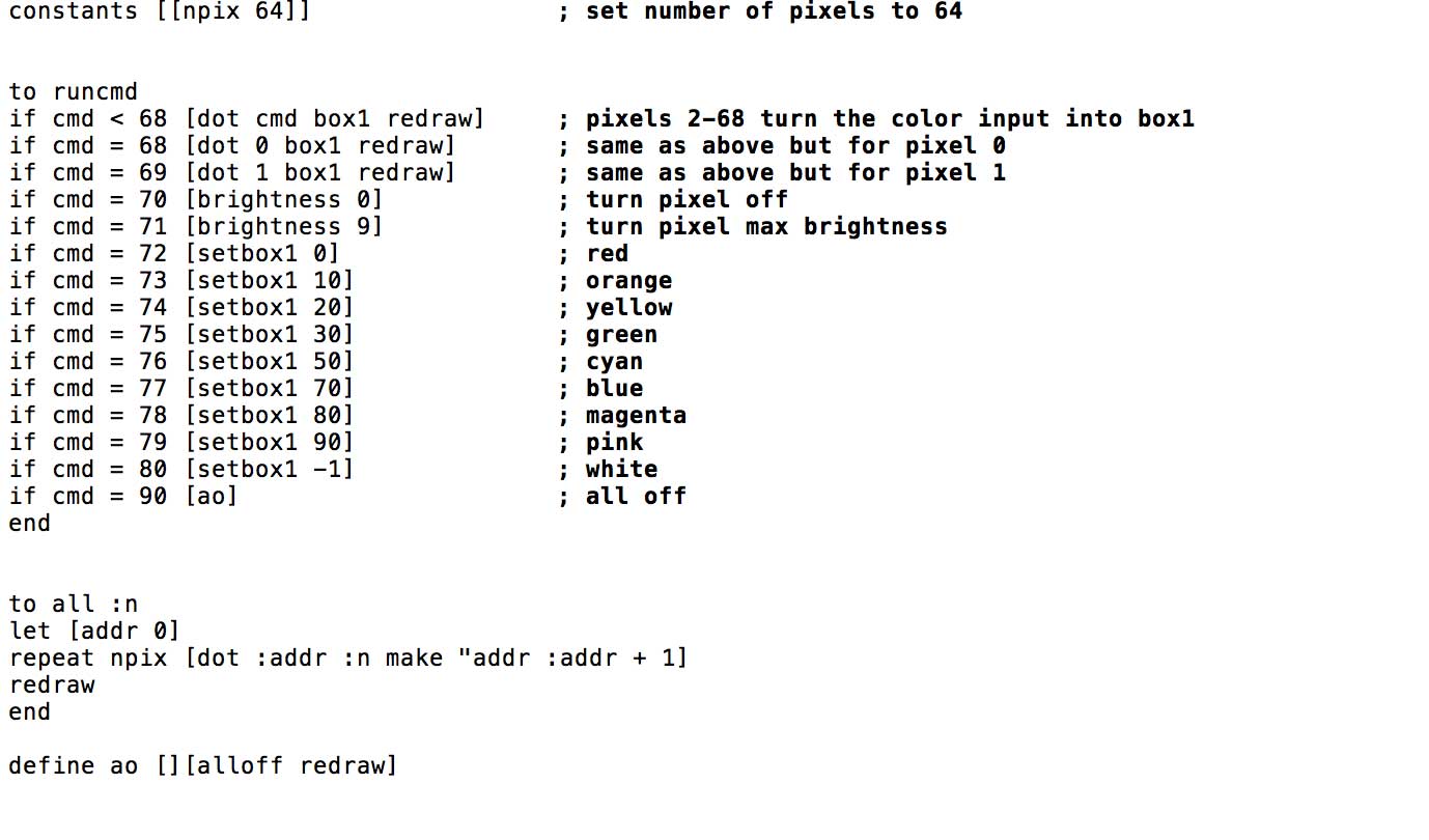
NOTE:I tried making "cmd = 0" & "cmd = 1" to control pixels 0 & 1 but it did not work. My understanding is that those commands are already taken for core functions in Logo. I needed to assign different numbers to those addresses. I chose cmd 68 & 69.
                    constants [[npix 64]]


to runcmd
if cmd < 68 [dot cmd box1 redraw]
if cmd = 68 [dot 0 box1 redraw]
if cmd = 69 [dot 1 box1 redraw]
if cmd = 70 [brightness 0]
if cmd = 71 [brightness 9]
if cmd = 72 [setbox1 0]
if cmd = 73 [setbox1 10]
if cmd = 74 [setbox1 20]
if cmd = 75 [setbox1 30]
if cmd = 76 [setbox1 50]
if cmd = 77 [setbox1 70]
if cmd = 78 [setbox1 80]
if cmd = 79 [setbox1 90]
if cmd = 80 [setbox1 -1]
if cmd = 90 [ao]
end


to all :n
let [addr 0]
repeat npix [dot :addr :n make "addr :addr + 1]
redraw
end

define ao [][alloff redraw]
With my program is completed. I saved the .txt file as MaxMsp_Controller_v2 and selected it in the Logo Programmer and downloaded it to the board. Everything worked fine and now it was ready to interface with MAX MSP.
---> building a Max Patch
Here is the end result of my Max patch
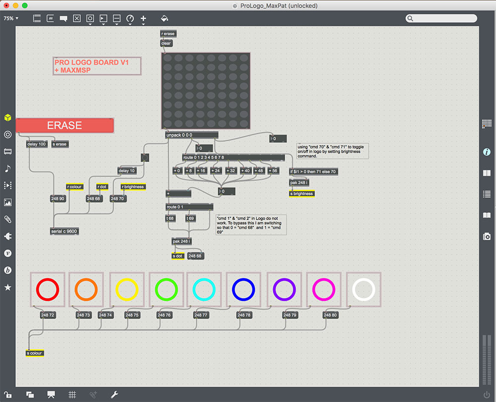
Communicating with microcontrollers in Max MSP requires using a serial object with the following attributes:
---> c = the serial port that was connected to my FTDI cable
---> 9600 is the baudrate of the ATTiny84 chip I was using.
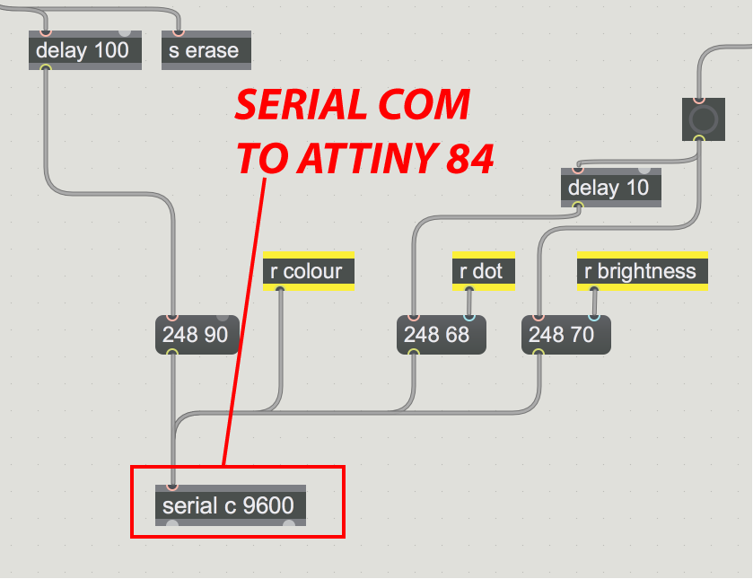
Next we need to send the Logo board command messages correlating to the ones in runcmd as demonstrated above.
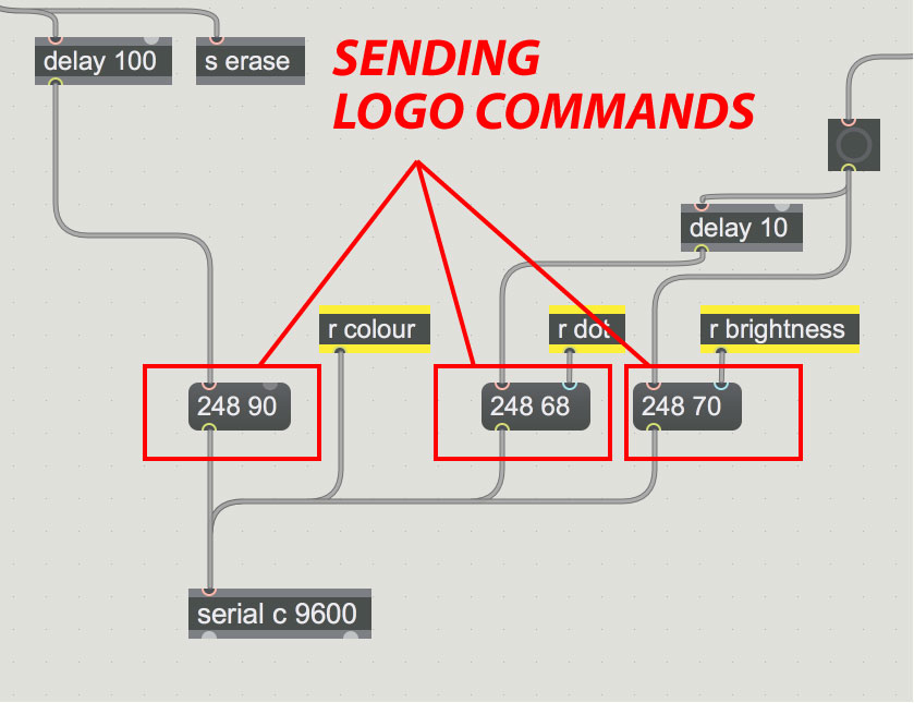
The second number equals the command number in logo. In the above image that means:
---> if cmd = 90 [ao]
---> if cmd = 68 [dot 0 box1 redraw]
---> if cmd = 70 [brightness 0]
Which means in this example that the erase button was pressed and that the first pixel was set to red.
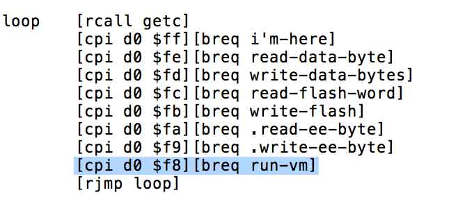
The number 248 refers to command given to send data in the Logo bootloader. It refers to this line but it at this level, it is above my head. $f8 refers to the byte that equals command 248. Here is the snippet from bootloader.txt that was used to setup my board.
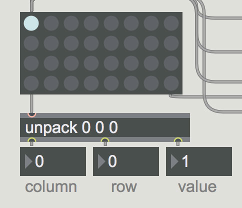
The next important feature of this patch is the matrixctlr object. This is the tool I used to control the pixel grid. The challenge with this object is that the grid starts at coordinates, 0,0.
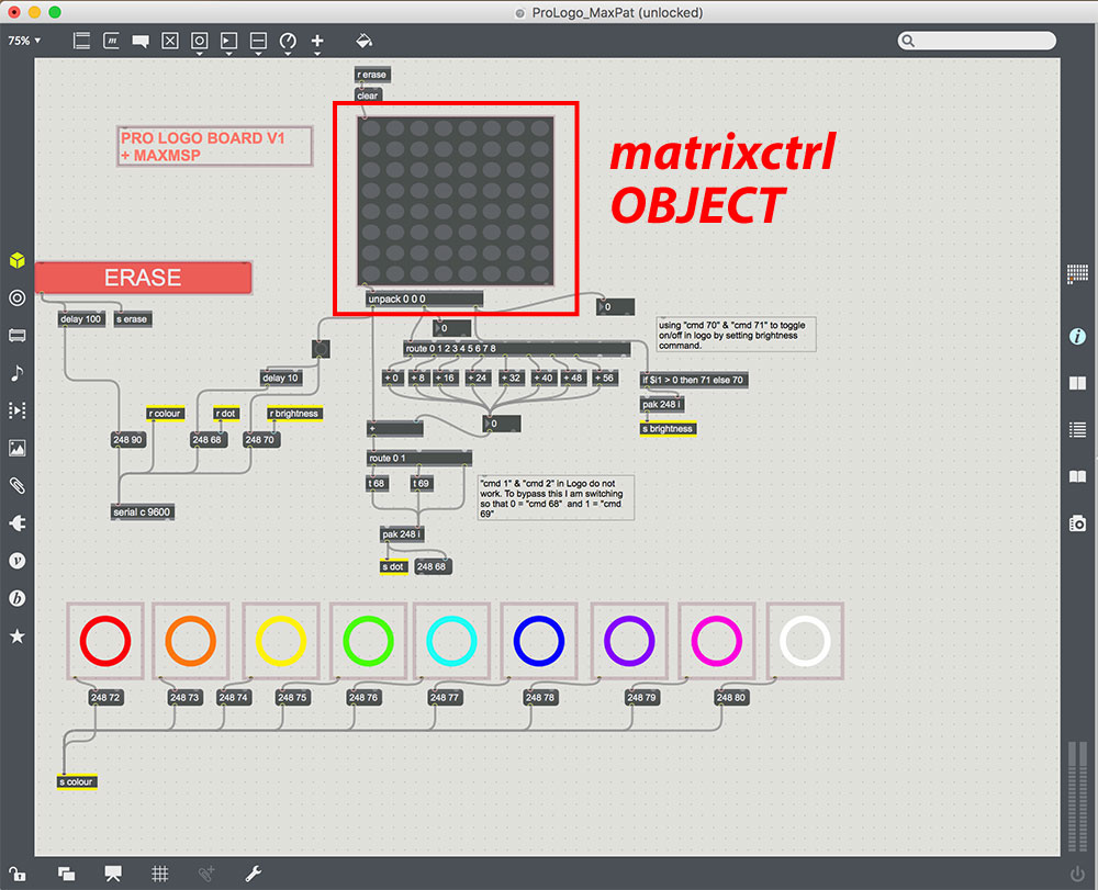
Which does not match the LED matrix so I needed to translate the controller buttons to match the matrix numbers. I am sure there would be an easier way to program this in to Logo as opposed to here what I did in Max MSP.
The following slides represent how I manipulated the numbers to get the command numbers I needed to match what Logo was expecting.
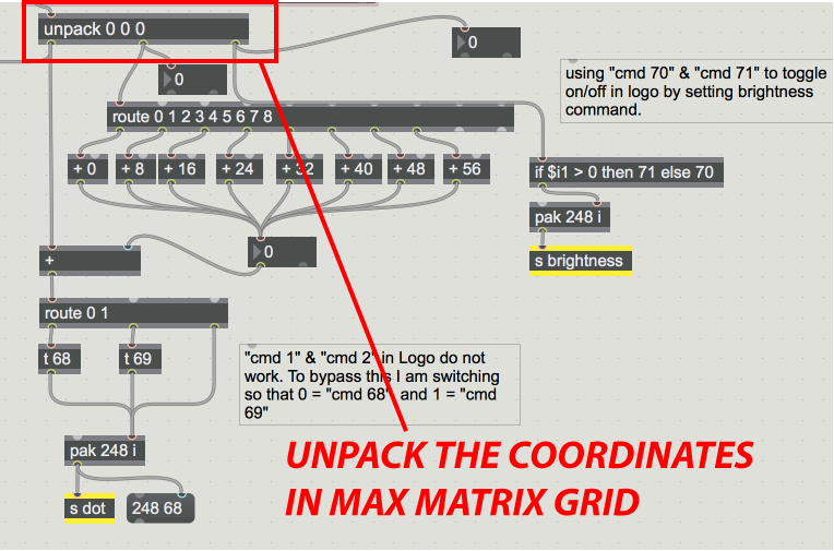
Getting a list of coordinates from the matrixctrl
This is used to send cmd 2-7 and to convert cmd 0 & 1 into 68 & 69 and to add the difference created by the row.
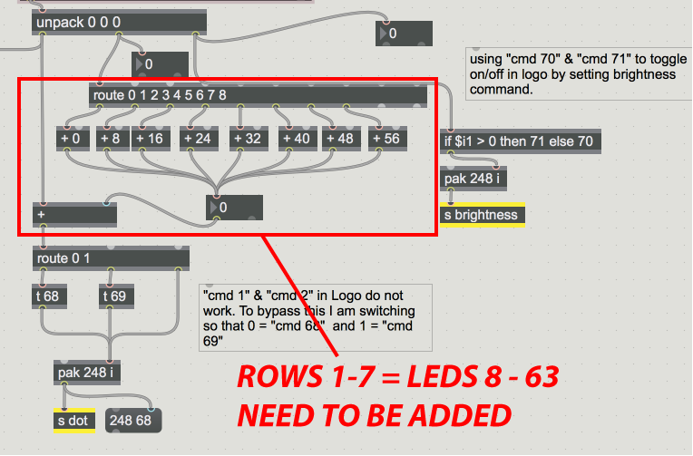
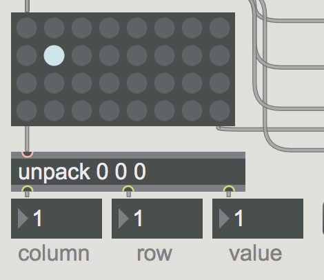
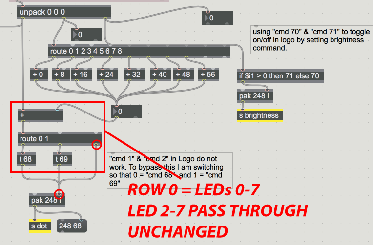
Here I added rows and compensate for the fat that the first row and the first column in the mtrixctlr = 0. For example: the button on the second row, second column on the matrixctlr = column 1, row 1. If you look at the pixel map above, that same spot on the LED matrix is 9. What this section of the Max patch does is add the difference. So we are adding a row of 8 dots to column 1 leaving us with a 9. This information is sent through the s dot box (send dot) which is then received and sent to the serial port.
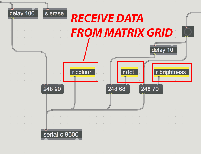
In total the serial object is receiving three commands which are sent using send and receive objects
---> s dot = send the location of the pixel
---> s brightness = whether the dot is on or off
---> s color = which color is chosen for the dot
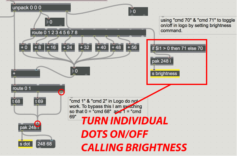
This looks for the values on/off value of the matrix buttons and converts them into 70 & 71 which equal our logo commands for brightness.
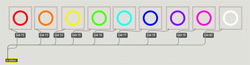
This section of the patch sends the right cmd for the color selection.
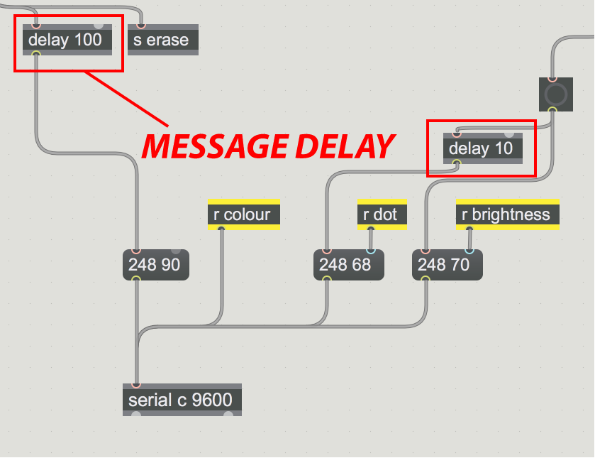
Delays are used to smooth the interaction down. 10ms was enough to avoid missing button presses and 100ms was used to smooth the erase feature.
All in all, this is probably one of my most exciting weeks as it ies in perfectly with my final project ambitions.
ASSIGNMENT FILES
---> LOGO (installation guide, bootloader, programmer, logo-vm, MaxMSP code, test code)
---> Max MSP Patch

This work is licensed under a Creative Commons Attribution-NonCommercial-ShareAlike 4.0 International License.