WEEK 14
NETWORKS & COMMUNICATION

ASSIGNMENT DETAILS design and build a wired &/or wireless network connecting at least two processors.

For this assignment I decided to try Neil's Serial RS-232 example and asynchronous communication. Our regional instructor, Craig, gave us a good rundown on how it works and there is also a good introduction on Sparkfun's site HERE. I am still fuzzy about it but I am determined to learn more over time because it can play such an important role in a lot of my creative work. This assignment was a funny one. It was mixed with success and failures. For this assignment, I found Anna Kazuinas's turorial page very helpful.


1ST ATTEMPT

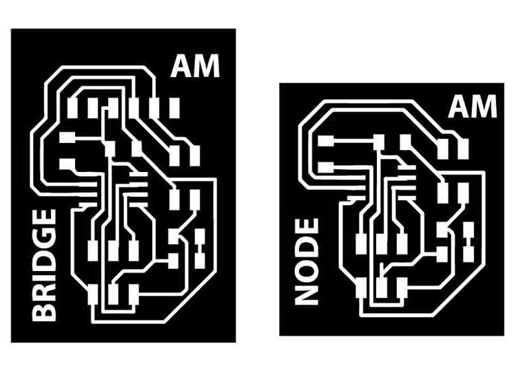
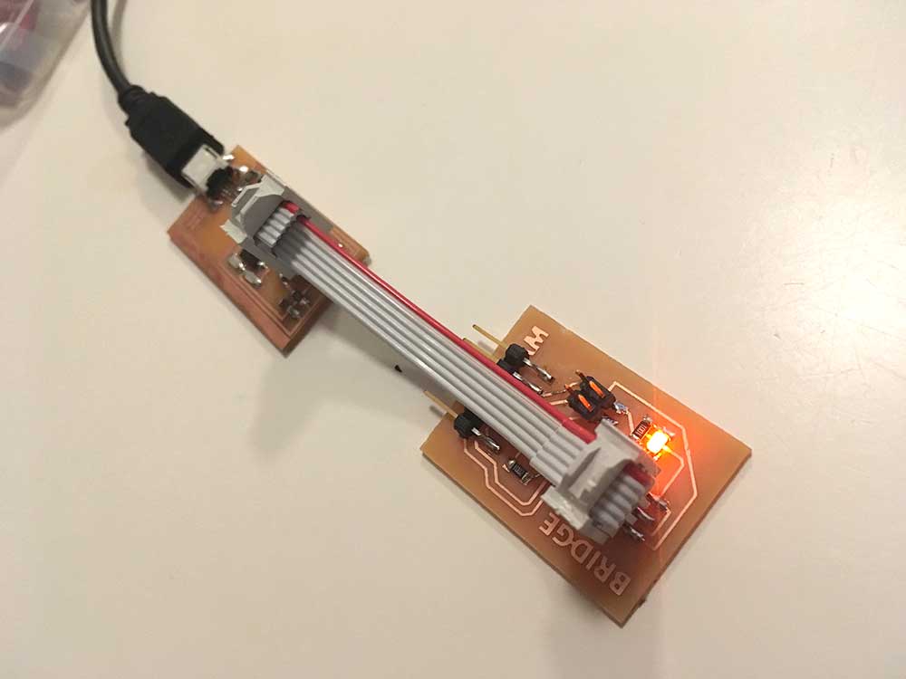
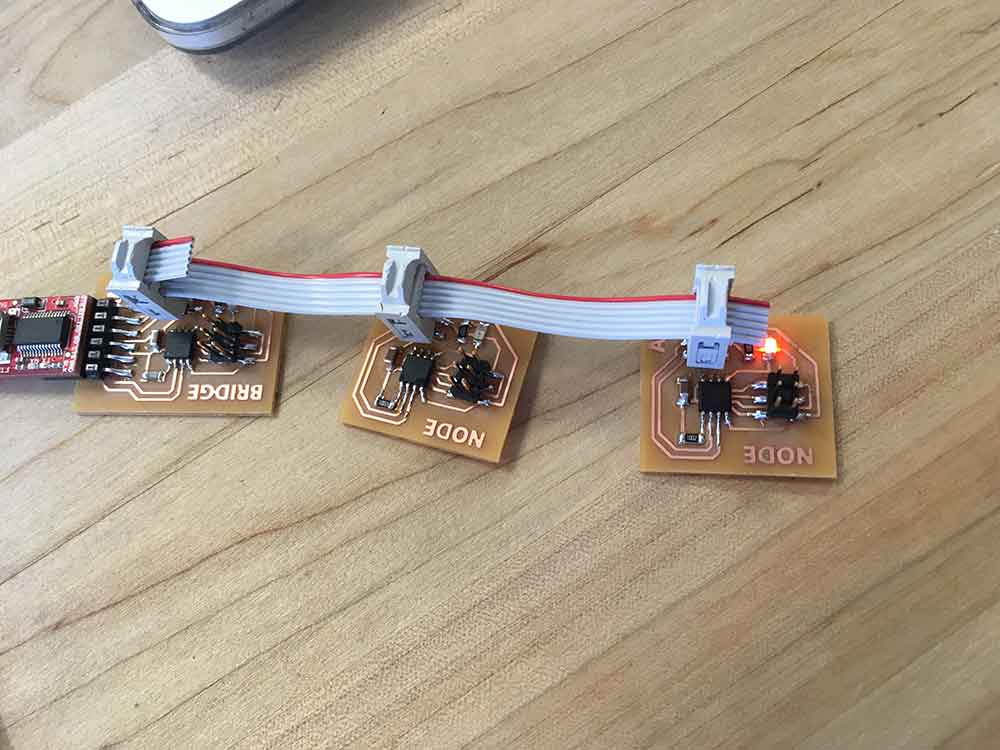
I didn't document making the boards. I basically redrew Neil's examples but made a couple stylistic changes in the way the LED and the resistor are placed.

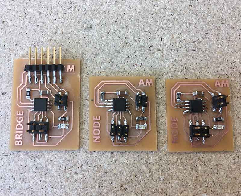
NOTE:These boards were cleaner before this image was taken. In an effort to debug some issues, I reworked some of the soldering.

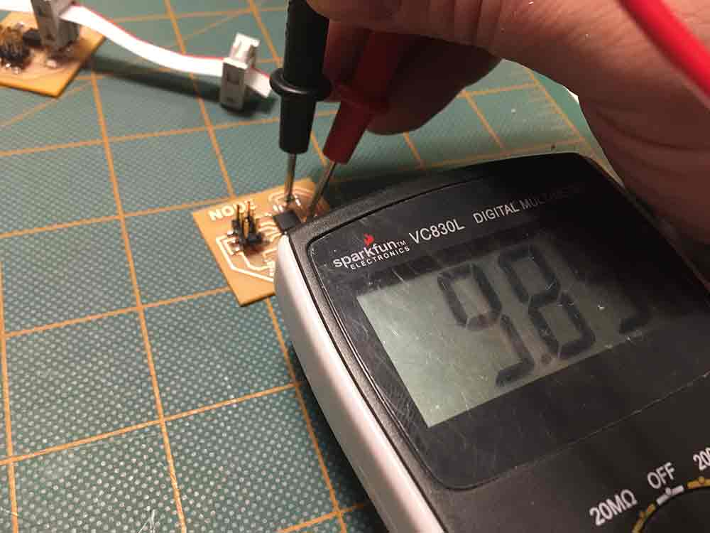
I first set the 3 boards up to

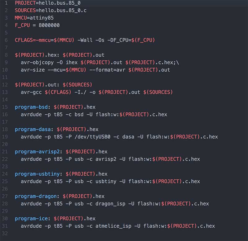
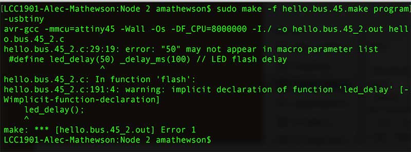
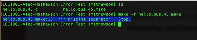
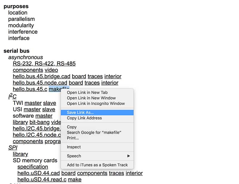
I decided to test one of the boards to see that it was working. I kept getting the same error. Over and over. I searched online and learned that makefiles are very sensitive to tabs and spaces. The message below suggests there is a separator missing.


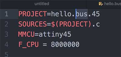
I noticed the makefile I downloaded from the Fab Academy site had an extra space next to a tab. I tried removing all the extra spaces and it didn't work.


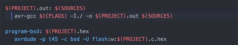
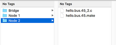
I decided to grab a makefile from a previous download where I was confident I did not have any problems. I took a look at the makefile from the Input week. Unlike the hello.bus.45.make file from this weeks assigmnet there were no extra spaces after the tabs. I find it hard to beleive that this is the issue. I copied over the makefile from input week and changed it from hello.light.45.make to hellos.bus.45.make. I also changed the project file name in the makefile to match.


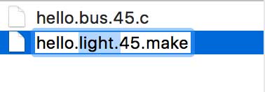
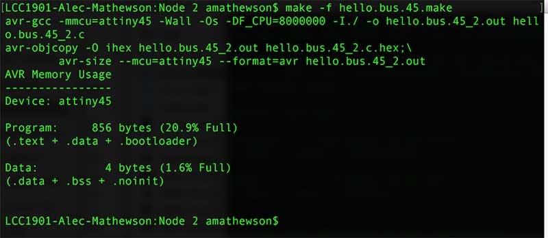
Using Terminal, I navigated to the folder containing the makefile I just renamed ("hello.bus.45.make") and typed:
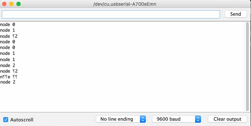
make hello.bus.45.make

So it worked. What this means is that there is something wrong with the hell.bus.45.make makefile. I find it very hard to beleive it is a space vs tab issue. Maybe it was the way I downloaded from the Fab Academy site (although this is not different from any other time) where I perform a right click on the makefile in the schedule, save file as and verified it was a .make file. Maybe there is some weird conversion happeing. I did not find other errors like this regarding this step. Anyways, if others read this post, makefiles are sensitive.


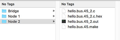
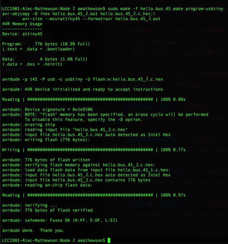
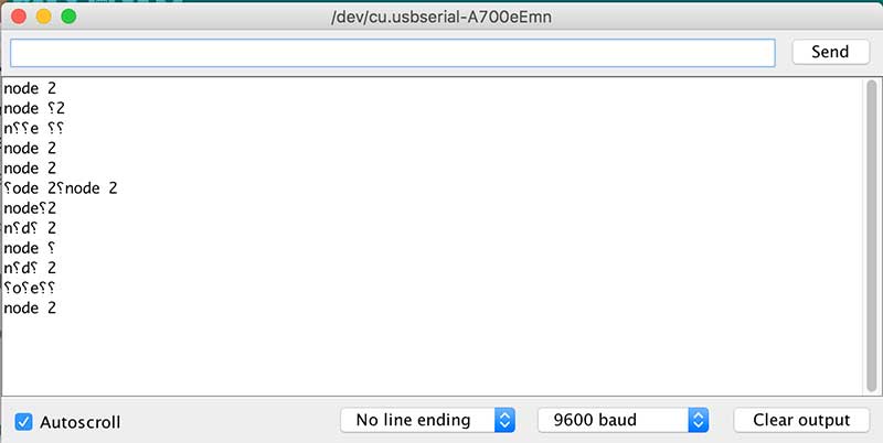
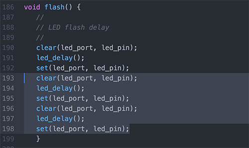
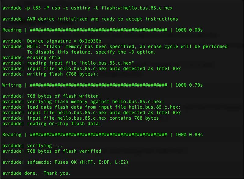
With a .hex and .out now present in the folder with the original .make and the .c code I was wable to successfully flash the board.

sudo make -f hello.bus.45.make program-usbtiny


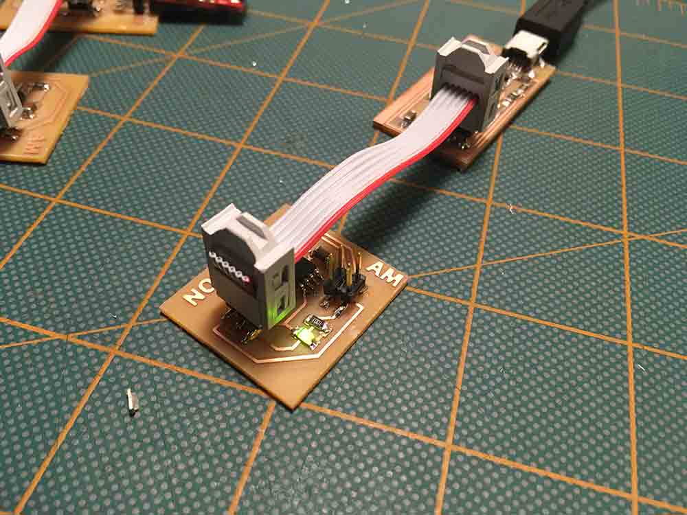
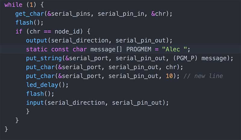
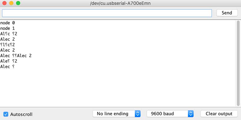
Time to setup this assignment and mess around!


2ND ATTEMPT

I made a bit of an error making my bridge board. I accidentally used a ATTiny85 instead of a 45. I then needed to adjust the makefile and replace all instances of 45 to 85


After this was done, I needed to make unique folders for each of the nodes and adjust the .c code to change the id of the boards. This is on Line 41 of Neil's code. For example, the the code for node 2 becomes:


---> bridge = #define node_id '0' (default as per Neil's code)
---> node 1 = #define node_id '1'
---> node 2 = #define node_id '2'


I chose to organize each of the unique boards into folders. There are other ways to do this but by using folders I am less likely to edit the wrong file. I also renamed each .c code file to respect the nodes.


Once I was organized I could generate the .hex files and continue to flash each board with it's respective codes.


I checked to make sure the makefile worked and that there was a .hex and a .out in each folder.

I plugged in each board into my FabISP. Made sure I was in the right directory for that particular board. And sent the command:

sudo make -f hello.bus.45.make program-usbtiny

NOTE: This is the output for the Node 2 board demonstrating it loaded properly.


When each board was programmed, the LED would stay on for a few seconds.


Once all my serial boards were programmed, I carefully connected them together with the ribbon cable I made. I made sure not to reverse polarity and that the RX and TX were properly connected. I also attached my FTDI Basic USB to serial adpater to the bridge board. I opened the Arduino IDE, set the right USB port for the FTDI and opened a serial window. I typed in the numbers for the boards, got a response and the LED's blinked. This was a good feeling.


But.... not all was right in "Serial land"! As you can see from the image and video below, Node 2 was occassional returning some junk. It was working but comming in with broken symbols more often than not. I suspect a connection issue. I did some more focused testing. Trying different positions on the cable to check connectors. I also tried other ribbon cables that seemed to work. Unless there is someting in the code that is not right, the problame was pointing to the board.


I also checked the resistors thinking one might be broken which would cause noise. Everything seemed ok as far as my multimeter was concerned. Connections and continuity.


I tried some more tests again and the problem seemed to get worse.


3RD ATTEMPT

I decided to ignore the noise on the signal and try a few things out. Messing around with the code and and seeing if I could get the lights to blink differently. I am still not familiar with c. I hope to improve on this with more time.

First I simply tried to change the response name.


I did this exercise on node 2. It worked but again, mixed with noise


Next I tried to slow the delay of the blinking LED. I wasn't quite sure where to do this and fankly did not spend the necessary time to research. I definitely will need to return to this but it is crunch time in Fab Academy land. At the time of this exercise I thought it best to try a few things then move on and catch up on all my other work.


---> first test

First test was to change _delay_ms from 100 - 500.

And... error.


I removed the 500 and tried to add a value in led_delay() and got a similar error.


---> second test

The LED blinking feature is clearly not operated how I was expecting. I decided to try and duplicate the lines that set the LED port on & off.

This worked but clearly it is not the right approach.


REFLECTIONS AND A CURIOUS PROBLEM


What you are witnessing here is me probing something I don't understand and learning from its behavior. This will require more research and effort but I look forward to it. As is with other assignments, the more I get through, the more I want to learn. Coding is the closest thing to magic.

A very intriguing problem arose that suggests I have a hardware or design flaw ith the node boards. After the blinking tests above, node 2 continues to include noise on the response. Node 1 had a curious problem. It was the node that worked fine. Now the LED will not turn off and it is unresponsive in the serial monitor. The other two work (minus the upside down question marks on node 2).


I went to line 33 in the .c code and I changed the pin from an output to an input. I wanted to see if the problem with the LED was a short. It successfully turned off the LED and I did not see any shorts on my multimeter.


I wonder if there is an issue putting traces under an LED? Which I do in all these boards. I re-checked my continuity. I re-soldered the pins, I tried a variety of combinations. The next step would be to remake the nodes and try a different routing but I will have to save this for another time.